Table of Contents
Advertisement
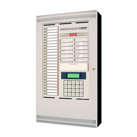
M R - 2 9 0 0
Fire Alarm Control Unit
I
NSTALLATION
M
ANUAL
September 2009
Document #: LT-2010 Rev.2
WARNING : This manual contains information on limitations
regarding product use and function and information on the
limitations as to liability of the manufacturer. The entire
manual should be read carefully.
Advertisement
Table of Contents

Subscribe to Our Youtube Channel
Related Manuals for Secutron MR-2900


Summary of Contents for Secutron MR-2900
- Page 1 M R - 2 9 0 0 Fire Alarm Control Unit NSTALLATION ANUAL September 2009 Document #: LT-2010 Rev.2 WARNING : This manual contains information on limitations regarding product use and function and information on the limitations as to liability of the manufacturer. The entire manual should be read carefully.
-
Page 3: Table Of Contents
1.9 Enclosure ........................6 1.10 Networking ........................6 1.11 Optional Integrated Printer ...................7 2.0 Installation .........................8 2.1 Unpacking the MR-2900 ....................8 2.2 Mounting and Assembling the MR-2900 ................9 2.3 Internal Assembly ......................10 2.4 Wiring ..........................12 3.0 Technical Specifications ....................23 4.0 Parts List ..........................25 5.0 Appendix A: Power Supply and Battery Calculations ............26... - Page 5 ..................44 Figure 32: MR-2900 and Silent Knight 5104 Dialer Wiring ..........45 Figure 33: MR-2900 and Silent Knight 5104 Dialer Wiring with addressable module substituted for common alarm relay ..............45 Figure 34: MR-2900 and Silent Knight 5104 Dialer Wiring with addressable module substituted for common supervisory relay ............45...
-
Page 7: Technical Information
1.0 Technical Information 1.1 General The MR-2900 Fire Alarm Control Unit provides capability for up to 24 Input Circuits, 8 Polarity Reversing Bell Circuits, network capabilities (with use of an MR-2910 Network Board) and 4 General Purpose Form "C" Relays as well as system operated relays for alarm, trouble and supervisory indication. If the MR-2900 is ordered with a printer, it is ordered under the panel number MR-2920. - Page 8 LED annunciation of system status. The operation of this port is software defined and requires the use of an MR-2109-x communications board. The MR-2109-3 Driver is for communication to MR-2614, MR-2644, and the following dialers MR-2900-DACT and MRDL. The MR-2109-4 Driver is for communication to the MV-2700 voice system.
-
Page 9: Front Panel
MR-2900 Installation Manual 1.3 Front Panel The system controls consist of 12 system switches and a 20 position alphanumeric keypad. The 12 system switches are factory defined for operations such as alarm acknowledge, signal silence and system reset. The 20-position keypad is used for: •... -
Page 10: Input Circuit Modules
Addressable Input Circuits There are two classes of addressable input circuits supported by the Control Unit: • "Class A" (Style 6) - This is a 4 wire circuit supporting addressable detectors and modules. It requires two input circuits, one for signal out and one for signal return. Up to 99 detectors and up to 99 modules can be connected to the circuit. -
Page 11: Terminal Board
MR-2900 Installation Manual 1.6 Terminal Board Field connections are terminated on the MR-2936 Terminal Board, which in addition to terminal blocks contains a portion of the circuitry for output circuits and relays. The Terminal Board includes connections for 24 input circuits, 8 supervised polarity reversing bell circuits, 4 general purpose Form "C" relays, 3 system Form "C"... -
Page 12: Power Supply
Note: Never disconnect or reconnect the batteries while AC power is off. 1.9 Enclosure The enclosure for MR-2900 Control Unit consists of a back box complete with power supply, inner door assembly complete with main control board, and outer door assembly. The back box and door assemblies are fabricated from 1/16"... -
Page 13: Optional Integrated Printer
• Addressable NAC circuits cannot be synchronized. 1.11 Optional Integrated Printer The MR-2900 Control Unit can be ordered integrated with the MR-2920 Printer. The MR-2920 Printer is a 20 column thermal printer. The Control Unit and Printer come in a larger cabinet (MR-2973) with the Printer in a compartment adjacent to the Control Unit. -
Page 14: Installation
ARE SUPERVISED INNER DOOR AND CPU POWER SUPPLY COMPARTMENT COVER OUTER DOOR WITH GLASS PANEL (MR-2920 SHOWN) Figure 2: MR-2900 Exploded View The basic MR-2900 package includes the following components: Backbox Outer door including: • Lock • Display window •... -
Page 15: Mounting And Assembling The Mr-2900
NFPA 72, or ULC-S524 and CEC Part 1 Section 32. Surface and Flush Mounting The MR-2900 can be mounted in either flush or surface mount installations. Before installing the MR-2900 Panel the following should be considered. 1. Determine a suitable location for mounting the FACP. Keep in mind that surrounding walls, fixtures, must not hinder access to internal components. -
Page 16: Internal Assembly
• MR-2944-BBL annunciator enclosure for eight strips Refer to LT-2020 MR-2944 Installation Manual detailed installation MR-2944 MR-2900 Main MR-2900 information. MR-2900 MR-2900 Figure 3: MR-2900 and MR-2944 in a Network Note: The MR-2944 must be physically located next to the Main MR-2900 Panel. - Page 17 MR-2900 Installation Manual 14-1/2" (368 mm) 7/8" (23 mm) lip each side 3/4" (19 mm) lip top and bottom 16-7/8" (429 mm) 4" (102 mm) 3" (76 mm) 1-1/4" (32 mm) 21-3/4" (552 mm) 27-1/2" 29-1/2" 26-1/2" (699 mm) (750 mm) (673 mm) 8-1/2"...
-
Page 18: Wiring
Figure 7. Figure 7: Conventional Style B (Class B) Wiring Note: 2-wire smoke detectors cannot be used on this type of circuit. This circuit may be wired on any of the 24 input circuits on the MR-2900 terminal boards. - Page 19 Figure 10: Smoke Detector Circuit Wiring, Style D (Class A) Wiring Note: This circuit is supported only by the MR-2938 Conventional "Class A" Input Circuit Module. This circuit may be wired on any of the 24 input circuits on the MR-2900 terminal boards.
- Page 20 • This circuit shall not be used to monitor fire alarm or supervisory initiating devices. This circuit may be wired on any of the 24 input circuits on the MR-2900 terminal boards. • All distances refer to total wire length.
- Page 21 Notes: • All distances refer to total wire length. • This circuit may be wired on any input circuit from 9 to 24 on the MR-2900 terminal boards. Table 3: Maximum Wiring Length for Addressable Circuits Gauge Belden No.
- Page 22 Addressable Modules The addressable module extended circuits are wired as shown on the next page in Figures 15 - 20. Figure 15: MRI-M500M Wiring Figure 16: MRI-M501 Wiring...
- Page 23 MR-2900 Installation Manual Figure 17: MRI-M502M Wiring Figure 18: MRI-M500S Wiring for Signalling Circuits...
- Page 24 NC 8 5 NC NO 7 4 NO COMMON 9 6 COMMON Figure 19: MRI-M500R Wiring for Form C Relay Use Figure 20: MRI-M500X Wiring Style Y (Class B) Bell Circuit This is a 2-wire Style Y (Class B) power-limited and Regulated 24 FWR supervised signalling (notification appliance) circuit.
- Page 25 MR-2900 Installation Manual Style Z (Class A) Bell Circuit This is a 4-wire Style Z (Class A) power-limited and Regulated 24 FWR supervised signalling (notification appliance) circuit. Devices are connected as illustrated in Figure 22. MR-2937 Maximum wire lengths are shown in Table 4. This is “Class A”...
- Page 26 Inner Door Ribbon Cables Two ribbon cables connect the Terminal Board to the Main Circuit Board. These cables are on the hinged side of the Inner Door and are long enough that the Inner Door can be fully opened without removing the cables. Ensure that the cables are not twisted and is seated properly in the connectors.
- Page 27 MR-2900 Installation Manual Table 5: Maximum Capacitance for Network Baud Rates Baud Rate Maximum Capacitance Maximum Network Nodes 9600 100 nF 4800 220 nF 2400 470 nF 1200 680 nF RS-232 Network Wiring RS-232 Network wiring uses three (3) wires between each panel (see Figure 27).
- Page 28 An example of the wiring is shown in Figure 28. Up to eight of each type of annunciator and either one dialer or one reverse polarity module can be connected to the MR-2900. If more than one Ω MR-2614 is used, the 3.9k...
-
Page 29: Technical Specifications
Compliance System Model: MR-2900 Series Fire Alarm Control Panel System Type: Local, auxiliary (using MR-2900-CITY), remote protected premise station (using MR-2900- CITY or MR-2900-DACT), central station protected premises (using MR-2900-DACT). Type of Service: A, M, WF, SS (with MR-2900-CITY or MR-2900-DACT) Type of Signalling: Non-coded Applicable Standards: NFPA 70 and 72, UL-864 Rev.9, ULC S-524, ULC S-527-99 Input (Initiating... - Page 30 Bell (Notification Appliance) Circuits Number & Type 8 Class B, NFPA Style Y/ Class A, NFPA Style Z Supervisory Current 1.0 mA, power limited Alarm Current 1.5 A, power limited (NAC/1.0 A, power limited, Releasing) Voltage 24 VDC, nominal, full wave rectified, unfiltered Ω...
-
Page 31: Parts List
MR-2900 Installation Manual 4.0 Parts List Model Description Basic Control Unit MR-2900 Basic Control Unit (with or without MR-2920 strip printer) Optional Modules MR-2928 Conventional Input Circuit Module, 8 Circuit, Software Selectable for 10 or 80 mA, smoke and contact circuits MR-2938 Conventional Input Circuit Module, 4 Circuit, "Class A", 80 mA, smoke and... -
Page 32: Appendix A: Power Supply And Battery Calculations
Specifications on page 23 for specifications. POWER REQUIREMENTS (ALL CURRENTS ARE IN AMPERES) Total Total Model Number Description Standby Alarm Standby Alarm Fire Alarm Control Unit (includes MR-2900 0.092 0.107 MR-2931, MR-2905, MR-2902 MR-2900 0.005 Unique LED’s MR-2910 Network Communication Module 0.005 0.005... -
Page 33: General
4 A total bell load necessitates at least 6 A hour battery (in terms of 20 hour rating). Note: The MR-2900 Control Panel is capable of driving a bell load of 8 A maximum. This restriction must be considered when laying out a bell system.. -
Page 34: Appendix B: Ulc Listed Compatible Smoke Detectors
6.0 Appendix B: ULC Listed Compatible Smoke Detectors The following conventional smoke detectors are ULC listed for compatibility with the MR-2900 Control Panel using Conventional Circuit Input Modules # of Devices # of Devices Make & Model Make & Model... - Page 35 MR-2900 Installation Manual # of Devices # of Devices Make & Model Make & Model /Circuit /Circuit Simplex Fenwal 2098-9110 PSD-7131/70-201000-001 Edwards PSD-7131/70-201000-002 6249C PSD-7131/70-201000-003 6250C PSD-7131/70-201000-005 6264C PSD-7130/70-201000-001 6266C PSD-7130/70-201000-002 6269C PSD-7130/70-201000-003 6270C PSD-7130/70-201000-005 6269C-003 PSD-7128/70-201000-001 6270C-003 PSD-7126/70-201000-002 Apollo...
-
Page 36: Ulc Listed Compatible Addressable Devices
6.1 ULC Listed Compatible Addressable Devices Typical Current Model Description Draw µA MRI-1251 Ionization type smoke detector MRI-1251B Ionization type smoke detector MRI-2251 Photoelectric type smoke detector MRI-2251B Photoelectric type smoke detector MRI-2251T Photoelectric type smoke detector w/ thermal element MRI-2251TB Photoelectric type smoke detector w/ thermal element MRI-2251TM... -
Page 37: Appendix C: Ul Listed Compatible Devices
7.0 Appendix C: UL Listed Compatible Devices 7.1 UL Listed “Class B” Smoke Detectors The following Listed 2-wire smoke detectors and bases are compatible with the MR-2900 Control Panel μ using the MR-2928 Conventional Input Circuit Modules (with compatibility identifier MR-2928). Up to 5 of smoke detector normal standby load may be connected to MR-2928 conventional initiating device circuit. - Page 38 Smoke Base Standby Manufacturer Detector Model Current Identifier Identifier Model 80 μA Fenwal CPD-7023 I3FE1 CPD-001 FE01A 80 μA CPD-7023 I3FE1 CPD-002 FE02A 80 μA CPD-7023 I3FE1 CPD-003 FE03A 80 μA CPD-7023 I3FE1 CPD-005 FE05A 60 μA CPD-7051 I3FE1 2-Wire FE51A 60 μA CPD-7051...
- Page 39 MR-2900 Installation Manual Smoke Base Standby Manufacturer Detector Model Current Identifier Identifier Model Gentex 224-25 102 μA Hochiki SIF-24F HD-2 HS-221D HB-4 102 μA SIF-24F HD-2 YBA-M221 HB-4 130 μA SIH-24F HD-3 HS-221D HB-4 130 μA SIH-24F HD-3 YBA-M221 HB-4 142 μA...
-
Page 40: Ul Listed "Class A" Smoke Detectors
7.2 UL Listed “Class A” Smoke Detectors The following Listed 2-wire smoke detectors and bases are compatible with the MR-2900 Control Panel using the MR-2938 Conventional Input Circuit Module with compatibility identifier as MR-2938. Up to 2.50 mA of smoke detector normal standby load may be connected to each MR-2938 conventional initiating device circuit. -
Page 41: Ul Listed Notification Appliances
MR-2900 Installation Manual 7.3 UL Listed Notification Appliances The following notification appliances, where a current rating is shown, may be used with the MR-2900 Control Units. Input Current at 24 VDC (in mA) Model Type Audible Visual Wheelock MT-12/24-R Multi tone Horn... - Page 42 Input Current at 24 VDC (in mA) Model Type Audible Visual CH-CF1-WS-24-CF-W Strobe Chime CH-DF1-WS-24-VF-R Strobe Chime CH-DF1-WM-24-VF-R Strobe Chime 46T-G6-24-WS-24-HF-R Strobe Bell, 6 in. 46T-G10-24-WS-24-HF-R Strobe Bell, 10 in. 46T-G6-24-WH-24-HF-R Strobe Bell, 6 in. 46T-G10-24-WH-24-HF-R Strobe Bell, 10 in. AS-2415W Audible Strobe 92 (combined)
- Page 43 MR-2900 Installation Manual Input Current at 24 VDC (in mA) Model Type Audible Visual AMT-24-LSM Multitone Strobe Signal, non sync AMT-24-MS Multitone Strobe Signal, non sync AMT-24-IS Multitone Strobe Signal, non sync AMT-24-SL Multitone Strobe Signal, sync AMT-24-SLM Multitone Strobe Signal, sync...
- Page 44 Input Current at 24 VDC (in mA) Model Type Audible Visual RSS-2415C Strobe RSS-243OC Strobe RSS-2475C Strobe RSS-24100C Strobe RSSP-2415C Strobe, retrofit plate RSSP-2430C Strobe, retrofit plate RSSP-2475C Strobe, retrofit plate RSSP-24100C Strobe, retrofit plate SM -12/24 Sync Module 25 (combined) DSM -12/24 Dual Sync Module 38 (combined)
- Page 45 MR-2900 Installation Manual Input Current at 24 VDC (in mA) Model Type Audible Visual GX90S-4-60 Piezo Horn/Strobe 60 cd 130 (combined) GX90S-4-110 Piezo Horn/Strobe 110 cd 235 (combined) GXS-4-15 Strobe 15 Cd GXS-4-15/75-W Strobe 15/75 Cd Wall GXS-4-15/75-C Strobe 15/75 Cd Ceiling...
- Page 46 Input Current at 24 VDC (in mA) Model Type Audible Visual P241575 (R) (W) Horn/Strobe P2475 (R) (W) Horn/Strobe P24110 (R) (W) Horn/Strobe P241575K Horn/Strobe P2475K Horn/Strobe P24110K Horn/Strobe P241575F Horn/Strobe S2415 (R) (W) Strobe S241575 (R) (W) Strobe S2475 (R) (W) Strobe S24110 (R) (W) Strobe...
- Page 47 MR-2900 Installation Manual Input Current at 24 VDC (in mA) Model Type Audible Visual SS241575ADAS Strobe MASS2415ADAS Horn/Strobe MASS241575ADAS Horn/Strobe RP2415ADA Strobe RP241575ADA Strobe RP2475ADA Strobe RP24110ADA Strobe...
-
Page 48: Ul Listed Analog Addressable Devices
The following Listed analog addressable smoke detectors, detector bases, monitor modules, control modules and fault isolator modules are compatible with the MR-2900 Control Panel using the MR-2909 and/or MR-2919 Addressable Input Circuit Modules. Up to 99 detectors and 99 monitor/control modules may be connected to each addressable communications circuit. -
Page 49: Ul Listed Compatible Door Holder/Releasers
M500S Control module M500R Relay Module M500X Fault isolator module 7.6 UL LIsted Compatible Door Holder/Releasers The following listed door holders are compatible with the MR-2900 and MR-2400 door holder/releaser circuits: Input Current Manufacturer Model Type at 24 VDC Harrington... -
Page 50: Appendix D: Interconnection To Other Equipment
8.0 Appendix D: Interconnection to Other Equipment 8.1 Radionics 2071C and 2071AC The wiring between the MR-2900 and the Radionics 2071C and 2071AC Dialers is as shown in the following diagram: Figure 30: MR-2900 and Radionics 2071C/2071AC Wiring An addressable module may be substituted for the alarm relay as follows:... -
Page 51: Silent Knight 5104
MR-2900 Installation Manual 8.2 Silent Knight 5104 The wiring between the MR-2900 and the Silent Knight 5104 Dialer is as shown in the following diagram: Figure 32: MR-2900 and Silent Knight 5104 Dialer Wiring An addressable module may be substituted for the common alarm relay as follows:... -
Page 52: Ctm City Tie Module
8.3 CTM City Tie Module The CTM is designed to interface between a control panel and a local city tie box. The interface from the control panel is via a 24VDC signal circuit. This module is intended for connection to the control unit at the protected premises. -
Page 53: Keltron 3158 Ttm
MR-2900 Installation Manual 8.4 Keltron 3158 TTM The Keltron 3158 TTM and the MR-2900 are wired together as shown below: Figure 36: MR-2900 and Keltron 3158 TTM Wiring Addressable control modules cannot be used with the Keltron 3158 TTM. Note: The Keltron 3158 TTM is separately listed equipment. Refer to the installation and wiring... -
Page 54: Warranty & Warning Information
•Software Secutron Secutron Most products contain software. - Page 55 MR-2900 Installation Manual breakdowns, interruptions, loss, destruction, alteration or other problems in the use of a product arising our of, or caused by, the software. Every fire is different in the amount and rate at which smoke and heat are generated. Smoke detectors cannot sense all types of fires equally well.
-
Page 56: Limited Warranty
During the warranty period, Secutron Inc. shall, at its option, repair or replace any defective product upon return of the product to its factory, at no charge for labor and materials. Any replacement and/or repaired parts are warranted for the remainder of the original warranty or ninety (90) days, whichever is longer. -
Page 57: Out Of Warranty Repairs
Products which Secutron Inc. determines to be repairable will be repaired and returned. A set fee which Secutron Inc. has predetermined and which may be revised from time to time, will be charged for each unit repaired. Products which Secutron Inc. determines not to be repairable will be replaced by the nearest equivalent product available at that time. - Page 60 No part of this publication may be reproduced, transmitted, transcribed, stored in a retrieval system, or translated into any language or computer language, in any form by any means electronic, magnetic, optical, chemical, manual, or otherwise without the prior consent of Secutron. Canada U.S.A 25 Interchange Way...
Need help?
Do you have a question about the MR-2900 and is the answer not in the manual?
Questions and answers