
Related Manuals for Ariston G.C.N.:47-116-65 (24 kW)


Summary of Contents for Ariston G.C.N.:47-116-65 (24 kW)
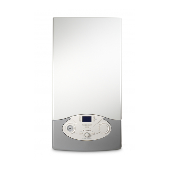
- Page 1 CLAS HE EVO CLAS HE EVO System CONDENSING WALL-HUNG GAS BOILER G.C.N.:47-116-65 (24 kW) G.C.N.:47-116-66 (30 kW) G.C.N.:47-116-67 (38 kW) G.C.N.:41-116-36 (18 kW) G.C.N.:41-116-37 (24 kW) G.C.N.:41-116-38 (30 kW)
-
Page 2: Table Of Contents
Hydraulic Unit .................... 52 Cylinder connection ................26 Main Heat Exchanger ................60 Internal mechanical time clock Burner Unit ....................61 Internal RF receiver for Ariston programmable Fan Unit ......................64 room thermostat .................. 27 Gas Valve ...................... 65 Electrical Diagram ..................28 Annual Maintenance ................ -
Page 3: Overview
The manufacturer’s guarantee is for 5 years from the date of purchase. The guarantee is invalidated if the appliance is not installed in accordance with the recommendations made herein or in a manner not approved by the manufacturer. To assist us in providing you with an effi cient after sales service, please register the guarantee online at www.ariston.co.uk CAUTION In the United Kingdom, installation, start-up, adjustments and maintenance, must be performed by a competent person only, in accordance with the current Gas Safety (Installation &... -
Page 4: General Information
overview Advice for the installer CE labelling The installation and fi rst ignition of the boiler must be The CE mark guarantees that the appliance conforms to the fol- performed by qualifi ed personnel in compliance with lowing directives: current national regulations regarding installation, and - 2009/142/CEE in conformity with any requirements established by relating to gas appliances... -
Page 5: Safety Regulations
overview Safety regulations and not slippery and that the ladders are fi tted with handrails on either side of the ladder and parapets on Key to symbols: the landing. Personal injury caused by falling from a height. Failure to comply with this warning implies the risk of During all work carried out at a certain height (generally personal injury, in some circumstances even fatal with a diff erence in height of more than two metres),... -
Page 6: Product Description
(Temperature regulation activated) shutdown Clip-in solar connected (optional) Heating operation set Note: A radio frequency (RF) Programmable Room Thermostat is available from Ariston stockists. Heating operation active The Receiver unit can be fi tted in the time clock position (10) -
Page 7: Overall View
product description Overall view CLAS HE EVO CLAS HE EVO SYSTEM 1. Flue connector 2. Manual air vent 3. Main heat exchanger 4. Detection electrode 5. C.H. Return temperature probe 6. C.H. Flow temperature probe 7. Silencer 8. Secondary heat exchanger 9. -
Page 8: Overall Dimension
product description Overall Dimensions CLAS HE EVO CLAS HE EVO SYSTEM 315 mod. 24 67 67 385 mod. 30/38 A. Central Heating Flow B. Domestic Hot Water Outlet C. Gas Inlet D. Domestic Cold Water Inlet E. Central Heating Return F. -
Page 9: Technical Information
product description Technical Data Model: CLAS HE EVO CE Certifi cation (pin) 0085CL0440 C13(X)-C23-C33(X)-C43(X)-C53(X)-C63(X) Boiler type C83(X)-C93(X)-B23-B23P-B33 Max/min nominal calorifi c fl ow rate (Pci) 22.0/5.5 28.0/6.5 31.0/7.5 Max/min nominal calorifi c fl ow rate (Pcs) 24.4/6.1 31.1/7.2 34.4/8.3 Domestic hot water max/min nominal calorifi c fl ow rate (Pci) 26.0/5.5 30.0/6.5 38.0/7.5... - Page 10 product description Model: CLAS HE EVO SYSTEM CE Certifi cation (pin) 0085CL0440 C13(X)-C23-C33(X)-C43(X)-C53(X)-C63(X) Boiler type C83(X)-C93(X)-B23-B23P-B33 Max/min nominal calorifi c fl ow rate (Pci) 18.0/4.5 22.0/5.5 28.5/6.5 Max/min nominal calorifi c fl ow rate (Pcs) 20.0/5.0 24.4/6.1 31.1/7.2 Max/min power output (80°C-60°C) 17.6/4.4 21.5/5.4 27.3/6.3...
-
Page 11: Installation
installation Reference Standards Flue In the United Kingdom, the installation and initial start-up of the Detailed information on fl ue assembly can be found in the boiler must be by a Gas Safe registered installer in accordance “Connecting the Flue” section. with the installation standards currently in eff ect, as well as with The boiler must be installed so that the fl ue terminal is exposed any and all local health and safety standards i.e. - Page 12 3mm on both poles. Alternatively, a fused 3 amp, 3 pin plug and unswitched socket ARISTON suggests the use of suitable anti-freeze products such as may be used, provided it is not used in a room containing a bath Fernox ALPHI 11, which will prevent rust and incrustation taking or shower, it.
- Page 13 installation Codensate Discharge 2. External termination of condensate drainage pipe via internal The condensate discharge hose from the boiler must have discharge branch (e.g. sink waste) and condensate siphon. a continuous fall of 2.5 and must be inserted by at least 50mm into a suitable acid resistant pipe - e.g.
-
Page 14: Installing The Boiler
installation Installing the Boiler Please check that you are familiar with the installation requirement before commencing work (pages 11 - 15). The installation accessories described in the following list are included in the boiler packaging: - Hanging bracket - A paper template (showing the dimensions of the boiler with 5 mm side clearances) - Connection valves (compression) - Screws and washers... -
Page 15: Gas Connection
installation Gas connection Instructions for opening the casing and performing an Make sure, using the labels on the packaging and the data plate internal inspection on the appliance itself, that the boiler is in the correct country Before performing any work on the boiler, fi rst disconnect it from and that the gas category for which the boiler was designed the electrical power supply using the external bipolar switch corresponds to one of the categories available in the country... -
Page 16: Underfl Oor Heating
installation To calculate the size of the heating installation, refer to the Underfl oor heating "Available pressure" graph below. For appliances with underfl oor heating, it is possible but not necessary to fi t a safety thermostat onto the underfl oor heating outlet. -
Page 17: Water Circuit Diagram
installation Water circuit diagram D D E E 1. Manual air vent 3. Burner 4. Detection electrode 5. C.H. fl ow temperature probe 6. C.H. return temperature probe 7. Secondary heat exchanger 8. C.H. pressure relief valve 10. By-pass 11. Drain valve 12. -
Page 18: Connecting The Flue
installation Connecting the Flue Flue System The provision for satisfactory fl ue termination must be made as described in BS 5440-1. The appliance must be installed so that the fl ue terminal is expo- sed to outdoor air. The terminal must not discharge into another room or space such as an outhouse or lean-to. -
Page 19: Fitting The Coaxial Flue (Ø 60/100 Horizontal)
installation Warning The exhaust gas ducts must not be in contact with or close Important to infl ammable material and must not pass through building Ensure that the fl ue is not blocked. structures or walls made of infl ammable material. Ensure that the fl ue is supported and assembled in accordance When replacing an old appliance, the fl ue system must be with these instructions. -
Page 20: Fitting The 5" Flue (Ø 80/125 Horizontal / Vertical)
installation Clamp Screws Seal Fig. 4 Fitting the 5” Flue (Ø 80 / 125 Horizontal/vertical) Once the boiler has been positioned on the wall, it is necessary to insert the Ø80/125 adaptor (Fig. 5) for both horizontal and vertical fl ue runs into the boiler fl ue socket (not supplied with fl ue kit - Part No 3318095). -
Page 21: Fitting The Coaxial Flue (Ø 60/100 Vertical)
installation Fitting the Coaxial Flue Note: See table for maximum and minimum fl ue runs. (Ø 60 / 100 Vertical) Contents: 1x Conical Adaptor (60/100mm) 1x Vertical Flue Kit (80/125mm) The vertical fl ue kit is supplied with a specially designed weather proof terminal fi tted, it can be used either with a fl at roof or a pitched roof. -
Page 22: Fitting The Twin Pipe (Ø 80/80)
Always ensure that the fl ue is adequately supported, using one fl ue bracket per extension and avoiding low points. (ARISTON supply suitable clamps as Part No. 705778). To utilise the air intake it is necessary to:... - Page 23 installation Fig. 9 AIR INTAKE MUST NOT BE FITTED ABOVE THE EXHAUST AIR INTAKE EXHAUST AIR INTAKE Fig. 10 For coaxial systems, the maximum development value, mentioned in the table below also takes into account an elbow. For twin fl ue systems the maximum development value, mentioned in the table includes the exhaust gas/air intake terminal.
- Page 24 installation Table of fl ue gas exhaust duct lengths Maximum Extension Exhaust-air (m) Diameter of pipe FLUE TYPE CLAS HE EVO CLAS HE EVO SYSTEM (mm) ø 60/100 Coaxial System ø 80/125 S1 = S2 24/24 26/26 16/16 36/36 24/24 26/26 ø...
-
Page 25: Electrical Connections
installation WARNING Peripheral unit connection Before performing any work on the boiler, fi rst To access peripheral unit connections carry out the following disconnect it from the electrical power supply using steps: the external bipolar switch and remove the fuse. - Disconnect the boiler from the power supply - Remove the casing by unhooking it from the instrument panel - Rotate the control panel while pulling it forwards... -
Page 26: Room Thermostat Connection
installation Room Thermostat / Remote Clock Connection To connect a room thermostat, it is necessary to: 1. Open the control panel 2. Loosen the cable clamp using a screwdriver and insert the wires leading from the room thermostat 3. Connect the wires to the terminals as indicated in the fi gure below, removing the link 4. -
Page 27: Internal Mechanical Time Clock
Fitting instructions for: • Internal mechanical time clock • Internal RF receiver for Ariston programmable room thermostat These instructions to be used in conjunction with the appliance installation instructions. Ensure the appliance is electrically isolated before working on the appliance. -
Page 28: Electrical Diagram
installation Electrical diagram The manufacturer is not responsible for any damage caused by For increased safety, ask a qualifi ed technician to perform a the lack of a suitable earthing system or by the malfunctioning of thorough check of the electrical system. the electricity mains supply. - Page 29 installation CLAS HE EVO SYSTEM Peripheral unit Peripheral unit connection - Remote Control (modulating device) FLOOR TA2/FLOOR - Underfloor heating thermostat SOL TA1 Room Thermostat 2 FLAME CN14 - Outdoor Sensor - Solar temperature probe - Room thermostat 1 CN25 SOL TA1 HV connection Detection electrode...
- Page 30 installation S plan wiring diagram.
- Page 31 installation S plan wiring diagram using an outside sensor.
-
Page 32: Commissioning
commissioning Initial preparation Thermo UK Ltd support the benchmark initiative. On pages Open the gas cock (supplied with the connection kit) to the pages 69 and 70 of this manual the Benchmark Commissioning appliance and check the gas connection on the appliance for Checklist and Service interval Record can be found. -
Page 33: First Igniton Operation
commissioning FIRST IGNITION OPERATION Date ......Installer ......1. -
Page 34: Ignition Procedure
commissioning Ignition procedure First ignition Press the ON/OFF button on the control panel to switch on the 1. Make sure that: boiler. The display shows: - The gas valve is closed; - The electrical connection has been properly carried out. Make sure that, in any case, the green/yellow earthing wire is connected to an effi cient earthing system;... -
Page 35: Test Function And Combustion Analysis
commissioning Combustion checking procedure Operation 3 - Adjusting the CO2 at maximum gas fl ow rate The order of operations for this procedure must always be (domestic hot water) respected. Draw off the domestic hot water at the maximum water fl ow rate (if a combi). - Page 36 commissioning Operation 4 - Checking the CO2 at minimum gas fl ow Checking slow ignition power With the Test function active, The soft light can be adjusted between the maximum power (shown on the display as “100”, i.e. 100%) and the minimum power rotate the encoder to select (shown on the display as “1”, i.e.
-
Page 37: Auto Function
commissioning Table summarising changes CLAS HE EVO CLAS HE EVO SYSTEM parameter Lower Wobbe index (15°C, 1013 mbar) ( MJ/m 3 ) 45,67 70,69 45,67 70,69 45,67 70,69 45,67 70,69 Slow ignition Minimum fan speed (%) Maximum central heating fan speed (%) Maximum D.H.W fan speed (%) Maximum heating power adjstment Gas valve restrictor (ø) -
Page 38: Boiler Protection Devices
boiler protection devices Boiler protection devices The fi rst fi gure of the error code (e.g. 1 01) indicates within which The boiler is protected from malfunctioning by means of internal operational assembly the error occurred. checks performed by the electronic microprocessor P.C.B., which 1 - Primary Circuit stops the boiler from operating if necessary. -
Page 39: Anti-Frost Device
boiler protection devices Multi-zone Heating (Heating Zone Modules - optional) 7 01 Zone 2 outgoing sensor defective 7 02 Zone 2 return sensor defective 7 03 Zone 3 outgoing sensor defective 7 04 Zone 3 return sensor defective 7 05 Hydraulic separation sensor defective 7 06 Zone 2 overheating... -
Page 40: Settings - Adjustment - Problem Identifi Cation Menus
settings - adjustment - problem identifi cation menus Accessing the settings - adjustment - problem identifi cation The parameters relating to each individual menu are listed in the following pages. menus The various parameters can be accessed and modifi ed using the OK The boiler can be used to manage the heating and domestic hot button and the encoder (see fi g. - Page 41 settings - adjustment - problem identifi cation menus Description value SERVICE CODE Rotate encoder clockwise to select code 234 and press O . Turn the encoder to select MENU and press OK button NETWORK DISPLAY SETTING Zone to be set by display 1 = 1 Zone 2 = 2 Zone 3 = 3 Zone...
- Page 42 settings - adjustment - problem identifi cation menus Description value BOILER PARAMETER - PART 2 Post-ventilation after heating request 0 = OFF 1 = ON Time delay after heating temperature from 0 to 60 Activated only with thermostat On/ increase (minutes) Off and heating control activated (parameter 421 - 521 - 621 = 01)
- Page 43 settings - adjustment - problem identifi cation menus Description value TEST & UTILITIES Test mode TEST+ = Max Heating power activation can also be obtained TEST+ = Max DHW power by pressing the Reset button TEST+ = Minimum power. for 10 seconds. The function is deactivated after 30 minutes or by pressing Reset Bleed cycle...
- Page 44 settings - adjustment - problem identifi cation menus Description value Parallel shift from - 7 to + 7 (low temperature) from - 14 to + 14 (high temperature) To adapt the thermal curve to the appliance requirements, it is possible to perform a parallel shift of the curve in order to alter the calculated fl ow temperature and therefore the ambient temperature.
- Page 45 settings - adjustment - problem identifi cation menus Description value Compensation from 0 to 20 if setting = 0, the temperature taken from the ambient sensor does not aff ect the calculation of the setting. If setting = 20, the temperature taken has maximum infl uence on the setting.
- Page 46 settings - adjustment - problem identifi cation menus Description value DIAGNOSTICS Zone 3 heat request 0 = OFF 1 = ON SERVICE PARAMETERS BOILER STATISTICS Number of hours burner operating in heater mode (xxh/10) Number of hours burner operating in hot water mode (xxh/10) Number of fl ame separations (nr/10) Number of ignition cycles (nr/10) Average length of heating request (minutes)
-
Page 47: Maintenance
maintenance Important Draining procedures Maintenance is an essential part of the safe and effi cient operation The heating system must be drained using the following of the boiler and ensures its durability. It should be performed procedure: according to the instructions given in current legislation. Perform - Switch off the boiler, make sure the external bipolar switch is in combustion analysis regularly in order to check the operating the OFF position and shut off the gas valve;... -
Page 48: Maintenance Guide
MAINTENANCE GUIDE 1. GENERAL ACCESS Lower the electrical front panel 1.1 General Access Tools TIME 3 min Unclip the cover to remove Remove the two screws Remove the combustion chamber front panel by releasing the clips Remove the front panel... -
Page 49: Electrical Unit
MAINTENANCE GUIDE 2. ELECTRICAL UNIT Unscrew the two screws and remove the cover 2.1 Control box access Tools TIME 4 min Remove the front panel as above and pivot the electricl box Unhook the two clip and rotate the cover... - Page 50 MAINTENANCE GUIDE 2.2 Fuse 2.3 Main P.C.B. Tools Tools TIME 5 min TIME 5 min Open the control box as above After opening the control box, disconnect the elctrical plug connections Remove the fuse Unhook and remove the P.C.B.
- Page 51 MAINTENANCE GUIDE 2.4 Display P.C.B. Tools TIME 5 min Unscrews the two screws and pull the assembly towards you Disconnect the elctrical plug connections and unhook and remove the P.C.B.
-
Page 52: Hydraulic Unit
MAINTENANCE GUIDE 3. HYDRAULIC UNIT Remove the clip and lift the motor from the diverter valve body. 3.1 RIGHT HAND HYDRAULIC BLOCK ASSEMBLY Drain the boiler (see 3.3). Remove the clip and lift the diverter valve from the assembly. Legend: 1 - Diverter valve motor 2 - Diverter valve 3 - Auto air vent... - Page 53 MAINTENANCE GUIDE 3.3 Draining 3.5 Primary water pressure sensor TIME 5 min Tools Tools Drain the boiler (see 3.3). Slide the fi xing clip, (it is held captive) TIME 5 min unplug the electrical connector and lift the sensor from the assembly.
- Page 54 MAINTENANCE GUIDE 3.6 Pump Remove the sensor (see 3.5) Tools TIME 10 min Drain the boiler (see 3.3). Remove the clip and the two screws Remove the AAV (see 3.4) Disconnect the pipe and then move the pump to the right to disengage Remove the pump...
- Page 55 MAINTENANCE GUIDE 3.7 C.H. Filter 3.8 D.H.W. Flow switch assembly Tools Tools TIME 5 min TIME 10 min Drain the boiler (see 3.3). Drain the boiler (see 3.3). Remove the clip and pull the fl ow Remove the clip and remove the fi lter switch assembly towards you Remove the fi lter Twist the fl ow switch assembly to disengage...
- Page 56 MAINTENANCE GUIDE 3.9 LEFT HAND HYDRAULIC BLOCK ASSEMBLY 3.11 Secondary heat exchanger Tools TIME 10 min Drain primary and domestic hot water circuits. Remove the two screws and remove the heat exchanger Legend: 1 - Left hand hydraulic block 2 - By-pass assembly 3 - Safety valve 4 - Central heating fl ow 5 - Domestic hot water outlet...
- Page 57 MAINTENANCE GUIDE 3.12 Condensate trap 3.13 Safety valve Tools Tools TIME 5 min TIME 5 min Unscrew the condensate trap from the condensate body Drain the boiler (see 3.3). Disconnect the discharge pipe. Remove the fi st clip on the left and pull the safety valve towards...
- Page 58 MAINTENANCE GUIDE 3.14 By-pass assembly 3.15 Temperature sensors Tools Tools TIME 5 min TIME 5 min Drain the boiler (see 3.3). Remove the second clip and pull the NTC1 : Black assembly towards you NTC2: Red NTC1 NTC2 Unplug the electrical connectors...
- Page 59 MAINTENANCE GUIDE Remove the clip and the temperature sensor 3.16 Manual Air vent Tools TIME 5 min Drain boiler (see 3.3) Unscrew and lift the manual air vent from the exchanger IMPORTANT ! Do not use conducting paste for the contact sensors because it will alter the resistance value.
-
Page 60: Main Heat Exchanger
MAINTENANCE GUIDE 3.17 Main heat exchanger Remove the burner unit Tools TIME 20 min Drain boiler (see 3.3) Remove the silencer Remove the four screws to free the heat exchanger Remove the two clips and disconnect the pipes. Isolate the gas supply and disconnect the gas pipe. Remove the four screws. -
Page 61: Burner Unit
MAINTENANCE GUIDE 4. BURNER UNIT Legend: 1 - Burner 2 - Silencer 3 - Gas diaphram 4 - Mixing tube 5 - Fan 6 - Detection electrode 7 - Ignition electrode 8 - Spark generator... - Page 62 MAINTENANCE GUIDE 4.1 Spark generator 4.2 Electrodes Tools Tools TIME 5 min TIME 5 min Unplug the ignition electrode from the spark generator. Unplug the electrodes Remove the screws and pull the electrodes towards you. Remove the screws and the spark generator...
- Page 63 MAINTENANCE GUIDE 4.3 Burner Remove the ten screws to free the burner door Tools TIME 15 min Remove the silencer Pull the burner toward you Replace any gaskets that are damaged or showing signs of deterioration Isolate the gas supply. Disconnect the gas pipe. Pull the assembly towards you Fan &...
-
Page 64: Fan Unit
MAINTENANCE GUIDE 4.4 Fan Remove the three screws to free the fan. Tools TIME 15 min Remove the combustion assembly (see 4.3) Legend: 1 - Fan 2 - Venturi 3 - Gasket Fan & mixer venturi according to the model Power Venturi diameter 18 kW... -
Page 65: Gas Valve
MAINTENANCE GUIDE 4.5 Gas Valve Remove the gas valve Tools TIME 15 min Remove the two screws under the boiler and disconnect the gas pipe on the top of the gas valve Legend: 1 - Gas valve 2 - Solenoids 3 - Throttle adjustment 4 - Off set adjustment 5 - Inlet test nipple... -
Page 66: Annual Maintenance
MAINTENANCE GUIDE 5. ANNUAL MAINTENANCE Plate heat exchanger Maintenance Interval: As necessary How: To measure specifi cation of DHW performance. By-pass & Safety valve Maintenance Interval: Annually How: Visual inspection / Clean as necessary Central heating fi lter Maintenance Interval: Annually How: Visual inspection / Clean as necessary Flow switch operation Maintenance Interval: Annually... - Page 67 MAINTENANCE GUIDE Primary Heat exchanger Maintenance Interval: Annually How : Visual inspection / Clean as necessary Condensate trap Maintenance Interval: Annually or after cleaning primary heat exchanger How : Visual inspection / Clean as necessary / Add water before replacing Pump Maintenance Interval: At the fi rst ignition and annually How: Check that the AAV is open /...
-
Page 69: Benchmark Service Interval Record
Failure to install and commission according to the manufacturer’s instructions and complete this Benchmark Commissioning Checklist will invalidate the warranty. This does not affect the customer’s statutory rights. If yes, and if required by the manufacturer, has a water scale reducer been fitted? CONDENSING BOILERS ONLY The condensate drain has been installed in accordance with the manufacturer’s instructions and/or BS5546/BS6798 If the condensate pipe terminates externally has the pipe diameter been increased and weatherproof insulation fitted? -
Page 70: Service Record
Service Record It is recommended that your heating system is serviced regularly and that the appropriate Service Interval Record is completed. Service Provider Before completing the appropriate Service Record below, please ensure you have carried out the service as described in the manufacturer’s instructions. - Page 72 Ariston Thermo UK Ltd Hughenden Avenue High Wycombe Bucks HP13 5FT Telephone: (01494) 755600 Fax: (01494) 459775 Internet: www.ariston.co.uk Technical Advice: 0333 240 7777 Customer Service: 0333 240 8777...
Need help?
Do you have a question about the G.C.N.:47-116-65 (24 kW) and is the answer not in the manual?
Questions and answers