
Related Manuals for Ariston ALTEAS ONE+ NET


Summary of Contents for Ariston ALTEAS ONE+ NET
- Page 1 ALTEAS ONE+ NET CUBE Room Sensor wireless with GENUS ONE+ WIFI INSTALLATION AND SERVICING INSTRUCTIONS CONDENSING WALL-HUNG GAS BOILER Country of Destination: GB/IE HOT WATER HEATING RENEWABLE...
-
Page 2: Table Of Contents
INDEX Overview ....................3 Commissioning ................30 General Information ................4 Initial Preparation ................30 Advice for the Installer..............4 Electricity Supply ................30 Data Plate Symbols .................4 Filling the Heating System ............30 Safety Regulations ................5 Filling of the DHW System ............30 UKCA Labelling .................6 Gas Supply .................. -
Page 3: Overview
ARISTON, as a leading manufacturer of domestic and commercial water heating appliances is committed to providing high quality products and a high quality after sales service. Advice on installation or servicing can also be obtained by contacting the ARISTON Technical and Customer Service Departments. -
Page 4: General Information
OVERVIEW Ensure the boiler is switched off before cleaning any exterior ATTENTION!! parts of the appliance. THE INSTALLATION AND FIRST Clean using a cloth dampened with soapy water. Do not use aggressive detergents, insecticides or toxic products. If the IGNITION OF THE BOILER MUST BE appliance is used in full compliance with current legislation, PERFORMED BY GAS SAFE REGISTERED it will operate in a safe, environmentally-friendly and cost-... -
Page 5: Safety Regulations
OVERVIEW SAFETY REGULATION Use electrical equipment suitable for its Key to symbols: intended use (in particular, make sure Failure to comply with this warning could that the power supply cable and plug are expose the user to the risk of serious or intact and that the parts featuring rotary or fatal personal injury reciprocating motions are fastened correctly);... -
Page 6: Ukca Labelling
OVERVIEW Damage to the appliance or surrounding If you detect a smell of burning or smoke, keep clear of the appliance, disconnect it from the objects caused by falling splinters, knocks and incisions. electricity supply, open all windows and contact Handle the appliance with suitable the technician. -
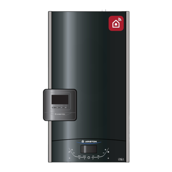
Page 7: Product Description
PRODUCT DESCRIPTION CONTROL PANNEL 24/06/21 16:24 10° 20,5° 00 02 04 06 08 10 12 14 16 18 20 22 24 40° 70° 1,5 bar COMFORT AUTO Central Heating Legend: 1. Display 2. WIFI button (enable / disable / configure) 3. -
Page 8: Display
PRODUCT DESCRIPTION OVERALL VIEW DISPLAY 26/10/21 16:19 10° 20,5° 00 02 04 06 08 10 12 14 16 18 20 22 24 42° 70° 1,5 bar COMFORT AUTO C Heating active 26/10/21 12:30 Date and time Keylock active 42° D.H.W. set temperature and indication of the set temperature level C.H. -
Page 9: Overall Dimension
PRODUCT DESCRIPTION OVERALL DIMENSIONS 67 67 385 - mod. 30-35 315 (24) 385 (30-35) A. Central Heating Flow B. Domestic Hot Water Outlet C. Gas Inlet D. Domestic Cold Water Inlet E. Central Heating Return Minimum clearances In order to allow easy access to the boiler for maintenance operations, The boiler must be installed in accordance with the clearances stated below. -
Page 10: Installation
INSTALLATION Codes of Practice Reference Standards Where no specific instruction is given, reference should be In the United Kingdom, the installation and initial start-up of the made to the relevant British Standard codes of Practice. boiler must be by a Gas Safe registered installer in accordance with the installation standards currently in effect, as well as BS7593: 2019: Treatment of water in domestic hot water with any and all local health and safety standards i.e. - Page 11 INSTALLATION Flue Connecting the Flue Detailed information on flue assembly can be found in the “ ” section. The boiler must be installed so that the flue terminal is exposed to the free passage of external air at all times and must not be installed in a place likely to cause nuisance.
- Page 12 If there is a requirement for greater demands, for example if the boiler has several Ariston suggests the installation of a magnetic filter on every bathrooms and cloakrooms, a vented or unvented hot water installation.
- Page 13 INSTALLATION Codensate Discharge 2(a). Connection of condensate discharge pipe downstream The condensate discharge hose from the boiler must have of a sink, basin, bath or shower waste trap. a continuous fall of 2.5 and must be inserted by at least 50mm into a suitable acid resistant pipe - e.g.
- Page 14 INSTALLATION 3. Connection of condensate pump - typical method (NB 4. Connection of condensate discharge pipe to external soil manufaturer’s detail instructions shoud be followed. and vent stack. Note: Requirements for any external pipe work shall be followed. 75mm 22mm Ø 1.
- Page 15 INSTALLATION 5. External termination to rainwater downpipe (NB only 7. Example of a purpose made soakaway combined foul/rainwater drain) >=500 L <=3000 ≤ 3000 9 10 Minimum pipe gradient Minimum pipe 1000 gradient 1000 1. Condensate discharge 6. External air break 1.
-
Page 16: Installing The Boiler
INSTALLATION Installing the Boiler Please check that you are familiar with the installation requirement before commencing work (pages 10 - 15). The installation accessories described in the following list are included in the boiler packaging: - Hanging bracket - A paper template - Connection valves (compression) - Screws and washers - Filling loop... -
Page 17: Gas Connection
INSTALLATION Gas connection Instructions for removing the housing and inspecting the Make sure, using the labels on the packaging and the data appliance. plate on the appliance itself, that the boiler is in the correct Before carrying out any work on the boiler, switch off the power country and that the gas category for which the boiler was supply using the and close the gas tap. -
Page 18: Underfloor Heating
INSTALLATION To calculate the size of the heating installation, refer to the "Available pressure" graph below. Graph representing the available circulation pump pressure ΔT20 1000 1100 1200 Underfloor heating For appliances with underfloor heating, it is possible but not necessary to fit a safety thermostat onto the underfloor heating outlet. -
Page 19: Water Circuit Diagram
INSTALLATION Water circuit diagram BEFORE THE DEVICE IS USED, FOR THE FIRST TIME THE TRAP MUST BE FILLED WITH WATER. The siphon is filled with water during deaeration procedure of the boiler (or heating system) - see p. 30 Ensure that the siphon contains water; if not, it must be refilled. -
Page 20: Connecting The Flue
INSTALLATION Connecting the Flue Flue System The provision for satisfactory flue termination must be made as described in BS 5440-1:2008. The appliance must be installed so that the flue terminal is exposed to outdoor air. The terminal must not discharge into another room or space such as an outhouse or lean-to. It is important that the position of the terminal allows a free passage of air across it at all times. - Page 21 INSTALLATION Minimum Length = 500 mm 150 mm 180 mm Fig. 2 Warning Important The exhaust gas ducts must not be in contact with or close to inflammable material and must not pass through building Ensure that the flue is not blocked. structures or walls made of inflammable material.
-
Page 22: Fitting The Coaxial Flue (Ø 60/100 Horizontal)
INSTALLATION Fitting the Coaxial Flue Note: A Plume management kit is available for 60/100 (Ø 60 / 100 Horizontal) horizontal termination. Instructions for installation are supplied with the Plume management kit. Contents: Draw a circle around the outer flue and cut the flue to the 1x Silicone O-Ring (60mm) required length taking care not to cut the inner flue, next cut 1x Elbow (90°) -
Page 23: Fitting The Coaxial Flue (Ø 60/100 Vertical)
INSTALLATION Before proceeding to fit the flue, ensure that the maximum flue length has not been exceeded (See the tables) and that all elbows and bends have been taken into consideration, for each additional 90° elbow 1 metre must be subtracted from the total flue length, and for each 45°... -
Page 24: Fitting The Twin Pipe (Ø 80/80)
Always ensure that the flue is adequately supported, using one flue bracket per extension and avoiding low points. (ARISTON supply suitable clamps as Part No. 705778). To utilise the air intake it is necessary to:... - Page 25 INSTALLATION When siting the twin flue pipe, the air intake and exhaust terminals must terminate on the same wall, the centres of the terminals must be a minimum of 280 mm apart and the air intake must not be sited above the exhaust terminal (refer to Fig.
-
Page 26: Table Of Flue Gas Exhaust Duct Lengths
INSTALLATION Table of flue gas exhaust duct lengths Maximum Extension Exhaust-air (m) ALTEAS ONE + NET Diameter of pipe FLUE TYPE GENUS ONE + WIFI (mm) ø 60/100 (*) ø 80/125 S1 = S2 1,5 = 1,5 32 = 32 1,5 = 1,5 23 = 23 1,5 = 1,5... -
Page 27: Electrical Connections
If the mains fuses need to be replaced, use 2A rapid fuses. SENSYS HD SYSTEM INTERFACE available as a accessory CUBE Me 27-OTT 12:30 10° standard for ALTEAS ONE+ NET 21° available as an accessory (GENUS ONE+ WIFI) ° Outdoor sensor °C available as accessory Room Thermostat 1... -
Page 28: Room Thermostat Connection
INSTALLATION Cube Room sensor (wireless) Connection To connect a room thermostat, read the instructions present in the kit delivered with the gas boiler. DO NOT CONNECT 240V TO ANY PERIPHERAL CONNECTIONS Room Thermostat / Remote Clock Connection To connect a room thermostat, it is necessary to: 1. -
Page 29: Electrical Diagram
The manufacturer is not responsible for any damage caused by the lack of a suitable earthing system or by the malfunctioning of the electricity mains supply. MADE IN ITALY GATEWAY WIFI Bk Bk Bl Br CN16 CUBE ALTEAS ONE+ NET MADE IN ITALY 230 V 230 V 230 V 230 V 230 V 230 V SOL TA1 CN21... -
Page 30: Commissioning
Initial preparation Open the gas cock (supplied with the connection kit) to the Ariston Thermo UK Ltd support the benchmark initiative. appliance and check the gas connection on the appliance for On pages 77 and 78 of this manual the Benchmark leaks. - Page 31 COMMISSIONING FIRST IGNITION OPERATION Date ......Installer ..... 1.
-
Page 32: Start-Up Procedure
COMMISSIONING Start-up procedure FIRST IGNITION Press the ON/OFF button on the control panel to switch on the AUTOMATIC PERFORM THE SYSTEM AIR PURGE AND THE boiler: the display will light up. CALIBRATION The initialisation procedure - indicated by the bar - begins. 1. - Page 33 COMMISSIONING • After the system air purge the 3. ACTIVATION OF THE DISAERATION PROCEDURE AND Automatic calibration display shows the gas set from AUTOMATIC CALIBRATION The current gas type set is: factory. • Switch on the boiler (by pressing the ON/OFF button) and Enter the type of gas used (if use the Mode button to select the standby mode, where no necessary), press the button b >...
- Page 34 COMMISSIONING Table B WARNING!! THE AUTOMATIC CALIBRATION MUST BE DONE IN Error Description CASE OF: Insufficient circulation. - REPLACEMENT OF: FAN, GAS VALVE, AIR/GAS Uncompleted calibration MIXER, BURNER, ELECTRODE. Make sure that: 01 - Flow Check Failed - REPLACEMENT OF P.C.B. - the pump works correctly - GAS CHANGEOVER - the water pressure in the...
- Page 35 Max Power DHW Max power CH COMMISSIONING Min Power 6. CO2 calibration Press ESC to return to the Chimney active CO2 calibration Draw off the domestic hot water at the maximum water flow home screen. Completed calibration Max Power DHW rate.
-
Page 36: Maximum Heating Power Adjustment
COMMISSIONING Maximun Heating Power adjustment The table indicate the existing relationship between the gas The maximum heating power can be adjusted to between pressure at the burner and the boiler power level in heating the maximum power allowed by the boiler and the minimum mode. -
Page 37: Gas Changeover
COMMISSIONING Gas Changeover The boiler is factory setted for the gas type indicated on the data plate. The adjustment, if necessary, must be performed by a Qualified Technician. It is not necessary a conversion kit, because the boiler has a auto adaptation gas system. Proceed as indicated: 1. -
Page 38: Auto Function
COMMISSIONING AUTO function This is a function which enables the boiler to automatically adapt its operation routine (the temperature of the heating elements) in line with the outdoor conditions, in order to 27/10/21 10:22 0° 40° 70° achieve and maintain the requested room temperature 1,5 bar conditions. -
Page 39: Boiler Protection Devices
BOILER PROTECTION DEVICES Appliance shut-off conditions Operation shutdown The boiler is protected from malfunctions by means of internal This type of error is “non-volatile”, which means that it is not checks performed by the electronic P.C.B., which stops the removed automatically. boiler from operating if necessary. - Page 40 BOILER PROTECTION DEVICES Table summarising error codes PCB System error Error list Warning Central Heating circuit Visibility The display shows: 1 01 Overheat Reset Display “Error 3 23 1 02 Pressure Sens Error Display Power off/on the boiler, then press reset also if this message appears again “...
-
Page 41: Anti-Frost Device
BOILER PROTECTION DEVICES NOTE - ERROR 804: TO CONNECT THE BOILER TO ELECTRONIC SOLUTIONS FOR SOLAR MANAGEMENT OR IBRID SYSTEMS (ONLY FOR COMBINATIONS NOT ADMITTED), IT’S NECESSARY TO INSTALL A CLIPIN SUPPLIED AS ACCESSORY CODE 3319171. Anti-frost Device The anti-frost function acts on the central heating flow temperature probe, independently from other regulations, when the electrical supply is turned on. -
Page 42: Technical Area
TECHNICAL AREA TECHNICAL AREA - reserved for qualified technician Example: Modification of parameter 2.3.1 Max. Adjustable Central Heating Power Accessing the Technical Area allows for setting/configuring Proceed as follows: the device according to the specific requirements of every installation procedure. 1. -
Page 43: Complete Menu Structure
TECHNICAL AREA COMPLETE MENU STRUCTURE Tecnical Area Service code ( > Press the programming key b to select 234 and press the button . reserved for qualified technicians Service Language, date and time - Follow the instructions of the display. Press OK button at each entry to save Boiler COMPLETE MENU - The parameters relating to each... - Page 44 TECHNICAL AREA description value description value SERVICE CODE 5 Heating ignition delay 0 = Deactivated 1 = 10 seconds Press th programming key b to select code 234 and press o 2 = 90 seconds 3 = 210 seconds COMPLETE MENU 8 Boiler version from 0 to 5 NETWORK...
- Page 45 TECHNICAL AREA description value description value 1 Warning Pressure from 4 to 8 3 D.H.W. switch Off logic 0 = Anti-scale (0,x bar) (stop at > 67°C) 1 = At 4°C over if the pressure falls down to the pre-set alert set-point value, the boiler will signal a malfunction warning (1P4...
- Page 46 TECHNICAL AREA description value description value RESET MENU’ 2 2 Slope from 1.0 to 3.5 (high temperature) 0 Reset Factory Settings Reset OK = yes from 0.2 to 1.0 ESC = no (low temperature) To reset all default parameter settings, press the OK button °C BOILER SETTINGS...
- Page 47 TECHNICAL AREA description value description value 4 Room Influence from 0 to 20 ZONE 2 PARAMETERS Proportional SETPOINT Auto Function active 2 T set Zone 2 from 35 to 82 (°C) If setted = 0 the room temperature doesn’t (high temperature) influence the calculation of the set-point.
- Page 48 TECHNICAL AREA description value description value 4 Diverter valve position 0 = D.H.W. 3 Offset from - 14 to + 14 (°C) 1 = Central Heating (high temperature) Auto Function active 5 D.H.W. Flow Rate (l/min) from - 7 to + 7 (°C) (low temperature) 7 Pump Modulation % To adapt the heating curve to the system...
- Page 49 TECHNICAL AREA description value description value WI - FI (only for ALTEAS ONE+ NET) DIAGNOSTICS 0 < Not Available> 19. 0 WI-FI CONFIGURATION 1 < Not Available> 19. 0. 0 Wi-Fi activation 0 = OFF 1 = ON 2 < Not Available>...
-
Page 50: Floor Drying Function
TECHNICAL AREA Floor Drying Function The Floor Drying Function is a special function that allows the installer, through a dedicated heating cycle, to use the boiler for drying a freshly poured radiant floor during a floor system installation. The installer can set parameter 2.7.4 (Floor Drying Cycle) and choose the cycle‘s operation (Functional Heating, Curing Heating, a combination of Functional and Curing Heating, or Manual Heating). -
Page 51: Maintenance
MAINTENANCE Important Operational test After having carried out the maintenance operations, ensure Maintenance is an essential part of the safe and the system is filled and bled fully of any excess air. efficient operation of the boiler and ensures its - Begin operating the boiler. -
Page 52: Maintenance Guide
MAINTENANCE GUIDE 1. GENERAL ACCESS Remove the front panel 1.0 Disconnect the boiler Before beginning maintenance work: a. Disconnect the appliance from the electricity supply. Press the ON/OFF button and wait 1 minute (the 3-way valve turn on Stand-by position) ATTENTION!! With the 3-way valve on heating position is not possible to remove the motor. -
Page 53: Electrical Unit
MAINTENANCE GUIDE 2. ELECTRICAL UNIT 2.1 Control box access Tools TIME 4 min Remove the front panel as above and pivot the electricl box 2.2 Fuse Tools TIME 5 min Open the control box as above Unhook the two clip and remove the cover Remove the fuse Unscrew the two screws and remove the cover of the instrument panel to have access to the main P.C.B. - Page 54 MAINTENANCE GUIDE 2.3 Main P.C.B. 2.4 Display P.C.B. Tools Tools TIME 5 min TIME 5 min After opening the control box, disconnect the elctrical plug Unscrews the two screws and pull the assembly towards you connections Front Unhook and remove the P.C.B. Disconnect the elctrical plug connections...
-
Page 55: Hydraulic Unit
MAINTENANCE GUIDE 3. HYDRAULIC UNIT Rotate clockvise to unhook the locking ring. 3.1 RIGHT HAND HYDRAULIC BLOCK ASSEMBLY Remove the 3 way valve motor. Legend: 1 - Diverter valve motor 2 - Diverter valve 3 - By-pass 4 - D.H.W. flow switch assembly 5 - C.H. - Page 56 MAINTENANCE GUIDE 3.3 Draining 3.5 Primary water pressure sensor Tools Tools TIME 5 min TIME 5 min Turn the drain valve anti-clockwise to open and drain the Drain the boiler (see 3.3). water from the boiler Slide the fixing clip, (it is held captive) unplug the electrical connector and lift the sensor from the assembly.
- Page 57 MAINTENANCE GUIDE 3.6 By-pass assembly 3.7 Pump Tools Tools TIME 5 min TIME 10 min Drain the boiler (see 3.3). Rotate clockvise to unhook the Drain the boiler (see 3.3). Remove the clip and the two screws locking ring of the diverter valve. Disconnect the pipe and then move the pump to the right to disengage Remove the clip and pull the assembly towards you...
- Page 58 MAINTENANCE GUIDE 3.8 C.H. Filter Remove the sensor (see 3.5) Tools TIME 5 min Drain the boiler (see 3.3). Remove the clip and remove the pressure gauge Remove the AAV (see 3.4) Remove the clip and remove the filter...
- Page 59 MAINTENANCE GUIDE 3.9 D.H.W. Flow switch assembly 3.10 LEFT HAND HYDRAULIC BLOCK ASSEMBLY Tools TIME 10 min Drain the boiler (see 3.3). Remove the clip and pull the flow switch assembly upward. Legend: 1 - Safety valve 2 - Central heating flow 3 - Domestic hot water outlet 4 - Secondary heat exchanger 3.11 Secondary heat exchanger...
- Page 60 MAINTENANCE GUIDE 3.12 Condensate trap Tools TIME 5 min Disconnect the condensate discherge pipe from the bottom of the boiler. Unscrerw the two screws. Disconnect the condensate pipe from the condensate trap...
- Page 61 MAINTENANCE GUIDE 3.13 Safety valve 3.14 Temperature sensors Tools Tools TIME 5 min TIME 5 min NTC1 : Black Drain the boiler (see 3.3). Disconnect the discharge pipe. NTC2: Red Remove the fist clip on the left and pull the safety valve towards you NTC1 NTC2...
- Page 62 MAINTENANCE GUIDE 3.15 Manual Air vent 3.16 Main heat exchanger Tools Tools TIME 5 min TIME 20 min Drain boiler (see 3.3) Drain boiler (see 3.3) Unscrew and lift the manual air vent from the exchanger Remove the silencer Isolate the gas supply and disconnect the gas pipe.
- Page 63 MAINTENANCE GUIDE Disconnect the cable of the electrode. Disconnect the plastic pipes from the manual air vent. Remove the four nuts and remove the burner unit Disconnect the heating flow pipe Disconnect the condensate pipe Remove the two clips to disconnet the exhanger on the hea- ting flow side...
- Page 64 MAINTENANCE GUIDE Unscrew the four screws to remove the heat exchanger...
-
Page 65: Burner Unit
MAINTENANCE GUIDE 4. BURNER UNIT Legend: 1 - Ceramic fibre 2 - Burner 3 - Silencer 4 - Mixing tube 5 - Fan 6 - Detection/Ignition electrode... - Page 66 MAINTENANCE GUIDE 4.1 Electrode (detection and ignition) 4.2 Burner Tools Tools TIME 5 min TIME 15 min Unplug the electrode on the control box Remove the silencer Remove the screws and pull the electrodes towards you. Isolate the gas supply. Disconnect the gas pipe. Disconnect the cable of the electrode.
- Page 67 MAINTENANCE GUIDE Pull the assembly towards you Remove the ceramic fibre. Remove the four screws and pull the burner toward you. Always replace the burner gasket (*). Verify and replace the other gaskets if they are damaged or showing signs of deterioration Remove the two screws and remove the electrode 4.3 Fan Tools...
- Page 68 MAINTENANCE GUIDE 4.4 Gas Valve Remove the three screws to free the fan. Tools TIME 15 min Remove the two screws under the boiler and disconnect the gas pipe on the top of the gas valve Remove the gas valve Remove the three nuts.
-
Page 69: Annual Maintenance
MAINTENANCE GUIDE 5. ANNUAL MAINTENANCE Plate heat exchanger Maintenance Interval: As necessary How: To measure specification of DHW performance. By-pass & Safety valve Maintenance Interval: Annually How: Visual inspection / Clean as necessary Central heating filter Maintenance Interval: Annually How: Visual inspection / Clean as necessary Flow switch operation Maintenance Interval: Annually How: Visual inspection / Clean as necessary / Check flow rate... - Page 70 MAINTENANCE GUIDE Primary Heat exchanger Maintenance Interval: Annually How : Visual inspection / Clean as necessary Condensate trap Maintenance Interval: Annually or after cleaning primary heat exchanger How : Visual inspection / Clean as necessary / Add water before replacing Pump Maintenance Interval: At the first ignition and annually How: Check that the AAV is open /...
-
Page 71: Technical Information
TECHNICAL DATA Model: ALTEAS ONE+ GENUS ONE+ WIFI 0085CU0034 CE Certification (pin) Gas category II 2HY203P C13(X)-C23-C33(X)-C43(X)-C53(X)-C63(X) Boiler type C83(X)-C93(X) B23-B23P-B33 22.0 / 2.6 28.0 / 3.0 31.0 / 3.5 Max/min nominal calorific flow rate G20 (Pci) Qn 24.4 / 2.9 31.1 / 3.3 34.4 / 3.9 Max/min nominal calorific flow rate G20 (Pcs) Qn... -
Page 72: Erp Data
B1 boiler yes/no Cogeneration space heater yes/no Combination heater yes/no ARISTON S.p.A. Contact details Viale A. Merloni 45 ( Name and address of the manufacturer or its authorised representative) 60044 FABRIANO AN - ITALIA ErP HEATING Power output Useful heat output at rated heat output and 21.5... -
Page 73: Product Fiche
η s Seasonal space heating energy efficiency η Water heating energy efficiency Sound power level, indoors PRODUCT FICHE - CUBE - WiFi Room sensor (only ALTEAS ONE+ NET) Brand Supplier identification model CUBE WIFI Temperature control class Energy efficiency contribution for space heating %... -
Page 74: Package Label - Instuctions To Filling
TECHNICAL DATA Package fiche PACKAGES OF COMBINATION HEATER, TEMPERATURE CONTROL AND SOLAR DEVICE The fiche for packages of combination heater, temperature control and solar device shall contain the elements set out in points (a) and (b): a) the elements set out in Figure 1, respectively, for evaluating the seasonal space heating energy efficiency of a package of combination heater, temperature control and solar device, including the following information:... - Page 75 TECHNICAL DATA Figure 1 Seasonal space heating energy e ciency of boiler ‘I’ Temperature control Class From che of temperature control I = 1%, II = 2%, III = 1,5%, IV = 2%, V = 3%, VI = 4 %, VII = 3,5%, VIII = 5% Supplementary boiler Seasonal space heating energy e ciency (in %) From che of boiler...
- Page 76 TECHNICAL DATA Figure 5 Water heating energy e ciency of combination heater ‘I’ Declared load pro le: Solar contribution - From che of solar device Auxiliary electricity (1,1 x ‘I’ - 10%) x ‘II’ - ‘III’ - ‘I’ = Water heating energy e ciency of package under average climate Water heating energy e ciency class of package under average climate <...
-
Page 79: Benchmark Commissioning Checklist
Benchmark Commissioning & Warranty Validation Service Record It is a requirement that the boiler is installed and commissioned to the manufacturers’ To instigate the boiler warranty the boiler needs to be registered with the manufacturer within one month of the installation. The warranty rests with the end-user (consumer), and they should be made aware it is ultimately their responsibility to register with the manufacturer, within the allotted time period. -
Page 80: Benchmark Service Interval Record
GAS BOILER SYSTEM COMMISSIONING CHECKLIST & WARRANTY VALIDATION RECORD Address: Boiler make and model: Boiler serial number: Commissioned by (PRINT NAME): Gas Safe registration number: Company name: Telephone number: Company email: Company address: Commissioning date: Heating and hot water system complies with the appropriate Building Regulations? Time, temperature control and boiler interlock provided for central heating and hot water Boiler Plus requirements (tick the appropriate box(s)) Weather compensation... - Page 81 SERVICE & INTERIM BOILER WORK RECORD It is recommended that your boiler and heating system are regularly serviced and maintained, in line with manufacturers’ instructions, and that the appropriate service / interim work record is completed. Service provider When completing a service record (as below), please ensure you have carried out the service as described in the manufacturers’ instructions. Always use the SERVICE/INTERIM WORK ON BOILER SERVICE/INTERIM WORK ON BOILER Date:...
- Page 82 SERVICE & INTERIM BOILER WORK RECORD It is recommended that your boiler and heating system are regularly serviced and maintained, in line with manufacturers’ instructions, and that the appropriate service / interim work record is completed. Service provider When completing a service record (as below), please ensure you have carried out the service as described in the manufacturers’ instructions. Always use the SERVICE/INTERIM WORK ON BOILER SERVICE/INTERIM WORK ON BOILER Date:...
- Page 84 Manufactured by Ariston S.p.A. Viale Aristide Merloni 45 60044 Fabriano (AN) ITALY ariston.com Imported by Ariston UK Ltd 3 Juniper West Basildon SS15 6SJ ariston.com/uk ariston.com 420011270900 - Rev. 03 - 072023...
Need help?
Do you have a question about the ALTEAS ONE+ NET and is the answer not in the manual?
Questions and answers