Table of Contents
Advertisement
Quick Links
Variants:
3741321009
3741321369
3757021009
3767021004
3767021009
3767021094
3767021099
3767021159
3767021249
Content:
Operation mod. 374
Operation mod. 375/376
Operation mod. 376 Japan
Description DMS module
Description of faults
Function diagram
Calibration (lin.)
PC configuration program
Replacement
Spare parts
Manual number:
17-05-01-329-b
Service Manual
for seca 374 / 375 / 376 CN
Description:
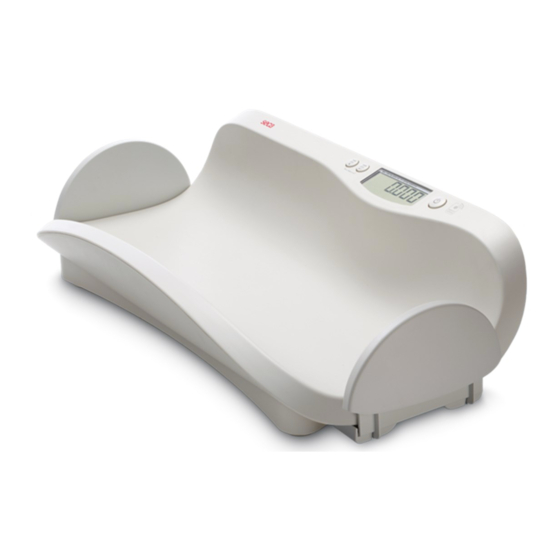
electronic babyscale multi load cell design, DMS low end module, LCD, for battery
use, prepared for mains operation.
Service Manual Number:
17-05-01-329-b
Valid as of:
17-10-06-301 a
17-10-07-496 c
17-10-07-513 c
30-34-00-645 b
30-34-00-588 c
25-01-02-560 a
30-34-00-603
30-34-00-672 b
30-34-00-726
30-34-00-727 b
01.03.2008
Advertisement
Table of Contents

Related Manuals for Seca 374


Summary of Contents for Seca 374
- Page 1 Service Manual Variants: for seca 374 / 375 / 376 CN 3741321009 3741321369 3757021009 3767021004 Service Manual Number: 3767021009 17-05-01-329-b 3767021094 3767021099 Valid as of: 01.03.2008 3767021159 3767021249 Description: electronic babyscale multi load cell design, DMS low end module, LCD, for battery use, prepared for mains operation.
-
Page 2: Mains Connection
EEPROM is integrated which is used to configure the module. A connection to the SeSAM bus (Seca’s Serial Autoconfiguring Multicontroller bus) is provided via which the scale can be calibrated and additional modules can be connected. - Page 3 Service manual Description of the electronics Display (only DMS low-end module and SLC highend) Whenever eight new measured values are available, i.e. approx. every 0.8 s, the weight is displayed. The display is an LCD which is controlled by duplex operation. A maximum of five digits as well as a few special characters can be displayed.
- Page 4 Service manual Description of the electronics If the start button is directly connected to this interrupt input, a button is obtained which is only active when the scale is switched off. It can be fitted under the platform, for instance, so that the scale is started by briefly stepping on it.
- Page 5 Service manual Description of the electronics Time base From the quartz’s 4.19MHz a time base is derived which controls all timed processes in the scale. These are, for instance, various timeouts and the on-time. After expiry of the on-time, the supply voltage for the analog part, for voltage measurement and for the EEPROM is switched off.
- Page 6 Service manual Description of the electronics Technical data Supply voltage: Load cell voltage + 0.5 V to 15 V Supply current: approximate load cell current Zero-signal current: typ. 2µA Operating temperature: approx. 0°C to 50°C Storage temperature: -10°C to 60°C 05.08.03 /Jensen / Rei 34-34-00-645 b...
- Page 7 Service manual Description of faults Please refer to the operating instructions to ensure that the scales were operated in the proper Please refer to the operating instructions to ensure that the scales were operated in the proper Please refer to the operating instructions to ensure that the scales were operated in the proper Please refer to the operating instructions to ensure that the scales were operated in the proper manner.
- Page 8 Service manual Description of faults Description of the Possible Remedy fault cause • • • Er:x:11 Sensor is Check connection cables, check sensor and replace as required defective or (if parts a replaced, a recalibration is necessary) supply lines • If several load cell are used, check the allocation (colour codes) are damaged •...
- Page 10 General: General: Seca scales with modular electronics are fitted with a software-controlled calibration device that is operated using the existing controls. This device can be used to recalibrate the scales or to set the scales to different GAL values. During development of the calibration device, special attention was paid to the following requirements: •...
- Page 11 Vogel & Halke File: 00603_e1.doc seca Created on: 30.06.1998 Printed on: 07.07.1999 Holger Panier / SE Pressing the kg/lbs key for less than 1.5 seconds causes the weight shown on the display to be increased or decreased by 10 g (depending on the mode currently selected). As the resolution of the display is lower, the displayed value will not necessarily be increased or decreased each time the kg/lbs key is pressed.
- Page 12 Vogel & Halke File: 00603_e1.doc seca Created on: 30.06.1998 Printed on: 07.07.1999 Holger Panier / SE Summary of a typical recalibration sequence: Summary of a typical recalibration sequence: Action carried out by the user Result The scales are switched off.
- Page 13 1 (2) PC configuration program page Instructions for PC-based configuration PC-based configuration is used for diagnosis or recalibration of all seca scales with modular electronics. The following equipment is required: • PC with serial interface (RS -232) • seca software 'SERVA”...
- Page 14 2 (2) PC configuration program page Standard case Connection to the existing display unit port. The display can instead be connected to the second modular socket of the service module. DMS module with integrated display 08-06-18-082 If there is no modular socket on the back of the PCB, retrofit one.
- Page 15 Service Manual Replacement instructions Mod. 374/375/376 Removing the power supply Before starting any work, unplug the mains plug and remove the batteries! ESD protection measures must be taken whenever work is performed on electronic components. 1. Opening the scale (page 2) 1.2 Open the battery compartment cover (B) and unscrew the screw (C).
-
Page 18: Spare Parts List
Service Manual Spare parts list seca 374 / 375 / 376 Item. Articel no. Designation Price stage 02-01-01-267-009 Frame 02-03-01-070-509 Mould compl. top, bottom, viewing glas, Push-buttons when order, please clearly indicate the print of puh buttons 01-22-13-319-009 Viewing glas 01-03-01-224-009 Support for load cell, mod.
Need help?
Do you have a question about the 374 and is the answer not in the manual?
Questions and answers