Table of Contents
Advertisement
Service Manual
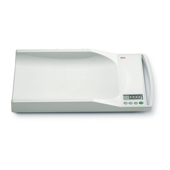
for seca 334 LC / 335 LC
Variants:
3341321008
3341321368
3357021094
3357021129
3357021159
Description:
Baby scale with 4 load cell technology
When servicing or repairing seca devices according to this service manual, always take note of the
instruction manual of the product. To download the latest version of the instruction manual and EMC
Recommendation go to
Contents:
Description electronic
Cableplan
Replacement
Spare parts
Spare parts
Spare parts
Spare parts drawing
EMC Recommendation
Instruction manual mod. 334 LC
Instruction manual mod. 335 LC
Instruction manual mod. 335 LC China
Manual number:
17-05-01-342-b
www.seca.com
.
30-34-00-864
08-02-06-036 a
30-34-00-752 a
334 1321008
334 1321368
335 7021159
30-34-00-749 b
30-35-00-219
17-10-06-335
17-10-07-552
17-10-07-555
Service Manual Number
17-05-01-342-b
Valid as of:
01.04.2013
Advertisement
Table of Contents

Related Manuals for Seca 334 LC


Summary of Contents for Seca 334 LC
- Page 1 Description: Baby scale with 4 load cell technology When servicing or repairing seca devices according to this service manual, always take note of the instruction manual of the product. To download the latest version of the instruction manual and EMC www.seca.com...
- Page 2 Service Instructions LC Electronics Service Instructions Electronics (LC) ODEL [334|335|382|383|384|385|769|799|780|833|834|835|869|899|874| 875|876|877|878|952|956] 03.04.2013/JEG 1 (24) 30-34-00-864...
-
Page 3: Table Of Contents
Contents Contents General Information........................3 Rating plates........................3 Structure and function of scale section ................4 1.2.1 Structure ......................4 1.2.2 Function ....................... 4 Calibration of Scales ........................6 ... -
Page 4: General Information
General Information General Information These service instructions are for technicians responsible for the maintenance and repair of devices. These persons must be familiar with all regulations governing electrical engineering and comply with them in all cases. These instructions are not intended for users without specialist skills. -
Page 5: Structure And Function Of Scale Section
General Information Structure and function of scale section 1.2.1 Structure The scale basically consists of the following parts: Base frame with up to four load cells Display unit with keypad Power supply (batteries, optional power pack) 1.2.2 Function... - Page 6 General Information LC compact modules (weight calculation and display) 08-06-18-142 or 08-06-18-160 Keypad DC supply Load Load Load Load cell cell cell cell Figure 3: Function chart [334|335|382|383|384|385|833|834|835|874|875|876|877|878|952|956] 03.04.2013/JEG 5 (24) 30-34-00-864...
-
Page 7: Calibration Of Scales
Calibration can be performed in one of two ways: The scales are equipped with an internal manual calibration feature, which is regulated by the control elements on the device. Calibration is performed with the help of seca serva Manual calibration of scale [334|335|382|383|384|385|833|834|835] Manual calibration is activated by plugging a jumper on the printed circuit board (see Figure 4). - Page 8 Calibration of Scales The following steps are necessary to perform manual calibration of the scale: 1. Switch on the scale and check the battery charge (see note). Calibration must not continue if the batteries are low! 2. Then switch the scale off and unscrew the lower service lid after having removed the seal.
- Page 9 Calibration of Scales 8. Then remove the weight from the scale, detach the jumper from the PCB and replace the service lid. 9. Now set up the scale again and switch on. Next, place a calibrated weight on the scale and check the display for the correct weight value. If manual calibration was successful, reseal the service lid according to the national regulations.
-
Page 10: Manual Calibration Of Scale [874|875|876|877|878|952|956]
Calibration of Scales Manual calibration of scale [874|875|876|877|878|952|956] Manual calibration is activated using a sliding switch (SJ1) on the PCB (see Figure 5). It is only accessible after breaking the seal and opening the scale. After changing the switch position to 2 ("CAL"), the scale has to be switched on to start manual calibration. - Page 11 Calibration of Scales 6. Place the calibrated weight in the middle of the weighing surface in one, or at most two steps of equal size. The calibration weight required may vary depending on the model (see Table 2). Model...
-
Page 12: Manual Calibration Of Scale [769|780|799|869|899]
Calibration of Scales Manual calibration of scale [769|780|799|869|899] Manual calibration is activated either by plugging a jumper or with newer models, by actuating a sliding switch on the printed circuit board (see Figure 6). These contacts are only accessible after breaking the seal and opening the scale. After plugging the jumper or actuating the sliding switch, the scale has to be switched on to start manual calibration. - Page 13 Calibration of Scales 3. The position 2 ("CAL") must be selected with the slide switch on the PCB, which is now accessible, or with older models, the two jumper contacts have to be connected using a jumper. 4. Then set up the scale properly and switch on.
-
Page 14: Calibration Of Corner Loading
Calibration of Scales 10. Now set up the scale again and switch on. Next, place a calibrated weight on the scale and check the display for the correct weight value. If linear calibration was successful, reseal the display housing according to the national regulations. - Page 15 Calibration of Scales 7. Once a corner load is identified on the weighing surface, the display will read "CAL E", followed by "E 1". A few seconds later it starts to flash, showing the weight to be placed on the scale.
-
Page 16: Troubleshooting
Troubleshooting Troubleshooting The following section contains an overview of possible error symptoms, their cause and the steps required to remedy them. The error messages generated by the device itself are also described below as well as the options for rectifying them. -
Page 17: Scale Error Messages
Error messages are displayed in the following form: "E xx" Error Error number (see Table 4) Displayed Cause Remedy Diagnosis with seca serva: Load cell defective, supply Check load cell connections E 11 leads damaged or electronics Poss. replace load cell or defective... -
Page 18: Error Messages [334|335|382|383|384|385|833|834|835|874|875|876|877|878|952|956]16
Troubleshooting seca serva: Recalibrate scale E 40 EEPROM data incorrect Replace electronics Table 4: Error messages [334|335|382|383|384|385|833|834|835|874|875|876|877|878|952|956] 3.4 Error messages [769|799|780|869|899] If a malfunction or defect occurs during operation of the scale, it is shown on the display as an error message. Error messages are displayed in the following form: "E mm.xx"... - Page 19 Troubleshooting Error when determining zero Protect scale from vibration / E XX.16 point on switch-on shocks during start-up seca serva: Recalibrate scale E XX.40 EEPROM data incorrect Replace electronics Check modular cable between display and weight E XX.60 Communication error...
-
Page 20: Measurements For Fault Localisation
B (see Appendix Load cell The most effective method for establishing a defect in the load cell is to use the seca serva diagnostic function. If this is not available, another option is to use a multimeter. - Page 21 Measurements for Fault Localisation Measurement between Ohmic resistance [Ω] and Sig (blue and red) ~250-300 and Sig (blue and white) ~250-300 and Sig- (black and red) ~250-300 and Sig (black and white) ~250-300 /Sig-/V /V- and aluminum > 1000 M...
-
Page 22: Replacing Electronics
Replacing Electronics 5 Replacing Electronics To replace faulty or defective electronics, proceed as follows: Attention: The electronics system of the scale includes electrostatically sensitive components! To replace faulty or defective electronics, proceed as follows: Check that both the workplace and the person replacing electronic components conform to the relevant ESD protection measures! ... - Page 23 Replacing Electronics Important note: To prevent battery short-circuiting, the contacts of the battery supply lead (see Appendices, item "B") must be additionally secured after soldering with a dot of glue to stop them from accidentally becoming detached and touching each other (e.g. due to mechanical loading or a defective soldered joint)! Here the solder contacts must be completely encased in glue of the type "Loctite 5145"!
-
Page 24: Appendices
Appendices Appendices Activation element for manual calibration Battery connection Figure 8: Electronic subassembly 08-06-18-142 Figure 9: Electronic subassembly 08-06-18-160 03.04.2013/JEG 23 (24) 30-34-00-864... - Page 25 Appendices Figure 10: Electronic subassembly 08-06-18-149 Figure 11: Electronic subassembly 08-06-18-147 03.04.2013/JEG 24 (24) 30-34-00-864...
- Page 27 Replacement seca 334 LC / 335 LC 12.11.2012 /SSC 1 (6) 30-34-00-752a...
- Page 28 Replacement seca 334 LC / 335 LC Content Safety measures ................................3 Safety instructions against electrostatic charging (ESD protection measures) ............3 Replacing the electronics unit and buttons ........................4 Replacing the electronics unit ..........................4 Replacing the button module..........................5 Replacing the load cell and the mains socket ......................
-
Page 29: I Safety Measures
Replacement seca 334 LC / 335 LC Safety measures Before starting any work on the scale, first disconnect the power supply (mains and batteries). II Safety instructions against electrostatic charging (ESD protection measures) ESD protective measures (electrostatic discharge) must be taken whenever work is performed on electronic components. -
Page 30: Replacing The Electronics Unit And Buttons
Replacement seca 334 LC / 335 LC 1 Replacing the electronics unit and buttons Please be sure to observe the sequence listed below when removing/fitting the parts! 1.1 Replacing the electronics unit x Unscrew the frame (A). x Unsolder the cables and loosen the screws (B). -
Page 31: Replacing The Button Module
Replacement seca 334 LC / 335 LC 1.2 Replacing the button module x Unsolder the button module and loosen the screws (C). Figure 3: Button module 12.11.2012 /SSC 5 (6) 30-34-00-752a... -
Page 32: Replacing The Load Cell And The Mains Socket
Replacement seca 334 LC / 335 LC 2 Replacing the load cell and the mains socket Please be sure to observe the sequence listed below when removing/fitting the parts! 2.1 Replacing the load cell x Unsolder the load cell from the electronics unit (D). - Page 33 Spare parts list 334 13 21 008 update Jan. 2013, valid until SN.: acc. to drawing 30-34-00-749 Item Article Designation Price stage A020101271509 Frame pre-assemled A020101272009 Cover for maintenance A020101273009 Covering cap A011305431009 Battery cover A010703003009 Battery contact, spring right A010703004009 Battery contact, spring...
- Page 34 Spare parts list 334 13 21 368 update Jan. 2013, valid until SN.: acc. to drawing 30-34-00-749 Item Article Designation Price stage A020101271509 Frame pre-assemled A020101272009 Cover for maintenance A020101273009 Covering cap A011305431009 Battery cover A010703003009 Battery contact, spring right A010703004009 Battery contact, spring...
- Page 35 Spare parts list 335 70 21 159 update Jan. 2013, valid until SN.: acc. to drawing 30-34-00-749 Item Article Designation Price stage A020101271509 Frame pre-assemled A020101272009 Cover for maintenance A020101273009 Covering cap A011305431009 Battery cover A010703003009 Battery contact, spring right A010703004009 Battery contact, spring...
- Page 36 Spare parts drawing seca 334 LC / 335 LC Figure 1: exploded view 21.01.2013 /SSC 30-34-00-749b...
Need help?
Do you have a question about the 334 LC and is the answer not in the manual?
Questions and answers