
Subscribe to Our Youtube Channel
Related Manuals for MGG Maxi Dog Fencing System


Summary of Contents for MGG Maxi Dog Fencing System
- Page 1 MGG Maxi Dog Fencing System Operating and Training Guide PLEASE READ THIS ENTIRE GUIDE BEFORE BEGINNING Suitable for up to 10 acres...
-
Page 2: Table Of Contents
Caution ....................19 Machines Gadgets and Gizmows Ltd contact details ....20 Please retain your original invoice for warranty purposes. MGG offer a return- to-base warranty for the collar-receivers of 3 months and the transmitters for 12 months against faulty manufacture. -
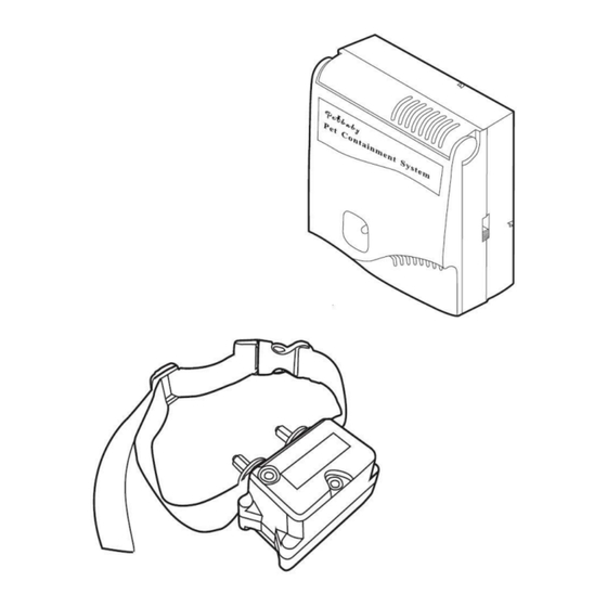
Page 3: Components
Wire stripping pliers Scissors Lighter Electrical tape Additional wire nuts or MGG Waterproof connectors Ground rod and clamp Waterproofing compound (e.g. silicone caulk) PVC pipe or water hose Circular saw with masonry blade ... -
Page 4: How The System Works
How the System Works The In-Ground Radio Fence has been proven safe, comfortable, and effective for all dogs over 7.5Kg. The system works by producing a radio signal from the Fence Transmitter through up to 1200 metres of Boundary Wire. The Boundary Wire is buried or attached to a fixed object to enclose the Dog Area. -
Page 5: Operating Guide
OPERATING GUIDE Locating the Fence Transmitter Step 1 Placing the Fence Transmitter In a dry, well ventilated protected area (1A, 1B). In an area where temperatures do not fall below freezing (e.g. garage, basement, shed, closet). Secured to a stationary surface using appropriate mounting hardware (not included). ... -
Page 6: Sample Layouts
Sample Layouts Sample 1: Perimeter Loop (Single Loop) The Perimeter Loop is the most common layout. This will allow your dog to freely and safely roam your entire property (2C). It can also protect gardens, pools and landscaping (2D). Sample 2: (2E) Perimeter Loop Using Existing Fence (Single Loop) This layout allows you to include your existing fence as part of your layout and keep your dog from jumping out or digging under your existing fence. -
Page 7: Positioning The Boundary Wire
If your splice pulls loose, the entire system will fail. Make sure your splice is secure. If MGG waterproof connectors are used please follow the instructions included with them. -
Page 8: Connecting The Wires To The Fence Transmitter
Additional Boundary Wire We recommend the use of MGG’s tough 1.8mm Super Wire as supplied with this MGG Maxi System for direct burial. Extra MGG Boundary Super Wire can be purchased in 200m rolls at www.MGG.co.nz Note: When adding Boundary Wire, it must still act as a continuous loop and waterproof connectors must be used. -
Page 9: Preparing The Receiver Collar
Step 5 Prepare the Receiver Collar Your Receiver Collar comes with short Contact Points installed. Use the long Contact Points for dogs with long or thick hair. Tighten the Contact Points with pliers one-half turn beyond finger tight. Check the tightness weekly. How to Replace the Battery Note: Do not install the battery while the Receiver Collar is on your dog. -
Page 10: Setting The Boundary Width And Testing The Receiver Collar
Function and Response Table Indicator Light Static Correction Receiver Collar Function Temperament of Dog Response Level 1 Flash No Static Correction, Beep only 2 Flashes Low Static Correction Timid 3 Flashes Medium Static Correction Timid or Average 4 Flashes Medium High Static Correction Average or High Energy 5 Flashes High Static Correction... -
Page 11: Installing The Boundary Wire
If the Receiver Collar does not beep at the desired range, adjust the Boundary Width Control knob to the desired setting. Turning the Boundary Width Control knob clockwise increases the Boundary Width while turning it counter clockwise decreases it. Repeat this procedure as needed until the Receiver Collar beeps at the desired distance from the Boundary Wire. - Page 12 Chain Link Fence (7A): Weave Boundary Wire through the links or use plastic quick ties. Wooden Split Rail or Privacy Fence (7A): Use staples to attach Boundary Wire. Avoid puncturing the insulation of the Boundary Wire. Double Loop with an Existing Fence: Run Boundary Wire on top of the fence and return it on the bottom of the fence to get the three to five foot separation needed.
-
Page 13: Placing The Boundary Flags
Place the Boundary Flags Step 8 During training the Boundary Flags are visual reminders for your dog of where the Warning Zone is located. 1. Hold the Receiver Collar at your dog’s neck height. 2. Walk towards the Warning Zone until the Receiver Collar beeps (8A). -
Page 14: Training Guide
TRAINING GUIDE IMPORTANT: Be Patient with your Dog Proper training of your dog is essential to the success of the In-Ground Radio Fence. Read this section completely before beginning to train your dog. Remember that the In-Ground Radio Fence is not a solid barrier. ... -
Page 15: Days 2 To 4: Continue Boundary Flag Awareness
he enters the Dog Area, even if you have helped with the leash. Wiggle a Boundary Flat to help your dog understand that the discomfort of the Static Correction happens around the flags. 4. Repeat this process at several different Boundary Flags. Your dog should start to resist going after the treat in the Static Correction Zone. -
Page 16: Days 9 To 14: Unleashed Supervision
Steps: 1. With full control of your dog on a leash, have the distraction presented. 2. If your dog does not move toward the distraction, praise and offer a treat. 3. If your dog does react to the distraction, allow him to go into the Static Correction Zone. 4. -
Page 17: Troubleshooting
TROUBLESHOOTING Check battery to make sure it is installed properly. Receiver Collar is not beeping or Check that both lights are lit on the Fence Transmitter. correcting. If not, perform the “Short Loop Test”. Make sure the Static Correction Level is set at 2 or above. The Receiver Collar is beeping, but ... -
Page 18: Short Loop Test
Additional Information The Boundary Wire is buried so that it is not accidentally tripped over or cut. Use care when using a weed eater or when digging near the Boundary Wire to prevent damage. The system should only be used with healthy dogs. Contact your veterinarian if you have concerns about the medical condition of your dog (medication, pregnant, heart conditions, etc.). -
Page 19: Terms Of Use And Limitation Of Liability
5. Locate the halfway point of your boundary and cut the Boundary Wire. 6. Splice the other end of the Test Wire to either side of your Boundary Wire where you cut it in half. 7. Plug in the Fence Transmitter and check the Loop Indicator light. If the Loop Indicator Light is on you can assume the break is in the other half of the Boundary Wire. -
Page 20: Machines Gadgets And Gizmows Ltd Contact Details
Made in China for Machines Gadgets and Gizmows Ltd., PO Box 592, Kerikeri New Zealand Website: www.MGG.co.nz Email: info@MGG.co.nz...
Need help?
Do you have a question about the Maxi Dog Fencing System and is the answer not in the manual?
Questions and answers