Table of Contents
Advertisement
Advertisement
Table of Contents

Related Manuals for Myson 2-Pipe


Summary of Contents for Myson 2-Pipe
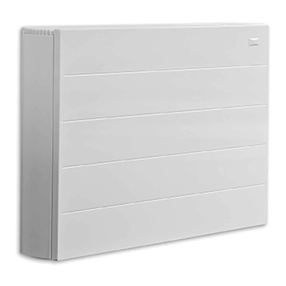
- Page 1 25278 iVector Installation Guide US 02/01/2013 09:24 Page 2 iVECTOR HEATER/COOLER 2 AND 4-PIPE MODELS. INSTALLATION, OPERATING, MAINTENANCE & AFTER SALES MANUAL JANUARY 2013, ISSUE 1 Product Serial Number: Please leave this manual with the end user. Part Number: 1371060 heatingthroughinnovation.
-
Page 2: Table Of Contents
25278 iVector Installation Guide US 02/01/2013 09:24 Page 3 Contents Introduction Warnings & Safety Measures Heating System Design Unit Selection/Sizing Location Preparation Fixing Water Connection Electrical Connection 10.0 Commissioning Procedure 11.0 Technical Data 12.0 Control System Set-up and Operating Instruction 12.1 Unit Operation 12.2... -
Page 3: Introduction
25278 iVector Installation Guide US 02/01/2013 09:24 Page 4 iVECTOR Heater/Cooler 1.0 Introduction This heater/cooler fan convector is designed for use on The unit is fitted with a washable air filter that can be easily central heating systems or heating and cooling systems in removed for cleaning. -
Page 4: Unit Selection/Sizing
25278 iVector Installation Guide US 02/01/2013 09:24 Page 5 iVECTOR Heater/Cooler 3.0 Heating System Design (continued...) Note: Pressure independent balancing and control valve kits are available for this product as an accessory. The valve kits can simplify system design by eliminating the possible need for larger balancing valves elsewhere in the system, and will maintain the flow in the unit to the required levels. -
Page 5: Preparation
25278 iVector Installation Guide US 02/01/2013 09:24 Page 6 iVECTOR Heater/Cooler 6.0 Preparation Before proceeding with the installation, remove the carton lid, unpack the contents carefully and check against the checklist below: 1. Heater/Cooler unit (chassis) 2. Outer Casing 3. Warranty Card 4. -
Page 6: Fixing
25278 iVector Installation Guide US 02/01/2013 09:24 Page 7 iVECTOR Heater/Cooler 7.0 Fixing " " NOTE: Do not replace outer cover until connection to system and connection to electrical supply has been completed. -
Page 7: Water Connection
Before making the pipework connections refer to section 3.0 for advice on System Design. Pipe Routing Options 2-pipe connection (The same options are possible for 4-pipe connection) " - 4 "* MAX... - Page 8 25278 iVector Installation Guide US 02/01/2013 09:25 Page 9 iVECTOR Heater/Cooler 8.0 Water Connection (continued...) Dimensions 2-pipe " " " " " " 6" " " Dimensions 4-pipe " 6 " " " " " COOL OUT HOT OUT HOT IN "...
- Page 9 25278 iVector Installation Guide US 02/01/2013 09:25 Page 10 iVECTOR Heater/Cooler 8.0 Water Connection (continued...) How to bleed/vent Condensate drain connection Spiggot size " O/D Connecting tube >1 " I/D Ensure all water fittings are secure before filling the system. This should be connected to a "...
-
Page 10: Electrical Connection
25278 iVector Installation Guide US 02/01/2013 09:25 Page 11 iVECTOR Heater/Cooler 9.0 Electrical Connection WARNING: This appliance must be grounded. The electrical installation must comply with state or local codes. l The electrical installation of this appliance should be carried For Building Management System out by a qualified electrician in accordance with current l Connect wires from BMS and valves as necessary, using the... - Page 11 3. Routing cable After making the electrical connections replace the side cover to the control box. BMS Connection Control Valve Connection Live Ground Neutral Cable Entry Points 2-pipe 0 valve POWER CONTROL BOARD BOARD Supply 120V 60Hz WATER SENSOR 2-PIPE SENSOR TRANSFORMER...
- Page 12 POWER Input 120V 60Hz CONTROL BOARD BOARD 24V 60Hz 24V DC Supply 120V 60Hz WATER SENSOR 2-PIPE SENSOR TRANSFORMER 2-pipe 1 valve + BMS 24V AC BUILDING MANAGEMENT SYSTEM CONTROL BOARD FAST SLOW HEAT COOL Supply 120V 60Hz 24V DC...
- Page 13 POWER CONTROL BOARD BOARD 24V 60Hz 24V DC COLD Supply 120V 60Hz WATER SENSOR 4-PIPE COOLING ONLY WATER SENSOR 2-PIPE SENSOR TRANSFORMER 4-pipe 2 valve + BMS 24V AC BUILDING MANAGEMENT SYSTEM CONTROL BOARD FAST SLOW HEAT Input 120V 60Hz...
-
Page 14: Commissioning Procedure
25278 iVector Installation Guide US 02/01/2013 09:25 Page 15 iVECTOR Heater/Cooler 10.0 Commissioning Procedure 1. l Fill and vent the system. l Open all valves fully and vent air from the heat exchanger. l Check for leaks at pipe connections. 2. -
Page 15: Technical Data
25278 iVector Installation Guide US 02/01/2013 09:25 Page 16 iVECTOR Heater/Cooler 11.0 Technical Data Performance Data 2-Pipe Heat Output (Btu/h) Cooling (Btu/h) Flow Model Entering Water - 65°F Air Temperature Condition 45-54-81 (gpm) Speed Total Sensible Normal 3051 3791 4543... - Page 16 25278 iVector Installation Guide US 02/01/2013 09:25 Page 17 iVECTOR Heater/Cooler 11.0 Technical Data (continued...) Dimensions Weight, Water Content and Motor Power 2 Pipe 4 Pipe 2 Pipe 4 Pipe Nominal Height Depth Length Motor Model Water Water Unpacked Unpacked (ins) (ins) (ins)
-
Page 17: Control System Set-Up And Operating Instruction
25278 iVector Installation Guide US 02/01/2013 09:25 Page 18 iVECTOR Heater/Cooler 12.0 Control System Set-up and Operating Instruction General Description Additional functions are available if necessary from the Full operating mode menu. The electronic control system on this unit provides a wide range A range of additional parameters and features can be changed of options that can be selected according to system complexity or activated in a further set up menu should these be required. - Page 18 25278 iVector Installation Guide US 02/01/2013 09:25 Page 19 iVECTOR Heater/Cooler 12.1 Unit Operation (continued...) Easy Mode Display Heating indicator Cooling indicator Temperature symbol – when this is displayed the current room temperature is displayed Fan speed symbol (fan blades will rotate when active) Comfort setting Power (on/off) Clock setting...
-
Page 19: Operating Modes
25278 iVector Installation Guide US 02/01/2013 09:25 Page 20 iVECTOR Heater/Cooler 12.2 Operating Modes Use ( ) and ( ) keys to choose from the following parameters. A function is selected when the icon is surrounded by Availability Function Description Adjustment Easy Full... -
Page 20: Installer's Set-Up Parameters
25278 iVector Installation Guide US 02/01/2013 09:25 Page 21 iVECTOR Heater/Cooler 12.3 Installer’s Set-up Parameters The various parameters that can be defined by the installer are Press (OK) to toggle the parameter setting or edit the value. shown in the table below. If the value starts to blink, use (+) and (-) keys to adjust the value. -
Page 21: Program Mode
25278 iVector Installation Guide US 02/01/2013 09:25 Page 22 iVECTOR Heater/Cooler 12.5 Program Mode Program Menu A quantity of 9 built-in (P1 - P9) and 4 user defined (U1 - U9) timed program options are available to choose from. Each day is divided into 24 one hour periods operating in either Comfort setting (21°C default) or Night set-back setting (19°C default). -
Page 22: Troubleshooting
Vent air from heating system unit cycling on water sensor If the fan convector is still faulty after checking the above, call your installer or MYSON Service. Possible Installation Faults System Diagnostic Poor heating or cooling performance from this unit could be the... -
Page 23: Maintenance
25278 iVector Installation Guide US 02/01/2013 09:25 Page 24 iVECTOR Heater/Cooler 14.0 Maintenance Disconnect from the power supply before carrying out maintenance work. Maintenance should be restricted to occasional removal of dust and lint around the unit. The outer surface may be wiped over with warm water and mild detergent taking care to avoid water entering the grille areas. - Page 24 25278 iVector Installation Guide US 02/01/2013 09:24 Page 1 MYSON INC 49 Hercules Drive, Suite 4904, Colchester VT0446 802 654 7500, 802 654 7022, info@mysoninc.com, www.mysoninc.com heatingthroughinnovation.
Need help?
Do you have a question about the 2-Pipe and is the answer not in the manual?
Questions and answers
**** will not go off & no display on panel
The Myson 2-Pipe system may not be turning off and showing no display on the panel due to the following possible causes:
1. Electrical supply switched off – Ensure the power supply is switched on.
2. Blown fuse – Check and replace the fuse if necessary.
3. Unit switched off – Turn the unit on using the LCD display.
If the issue persists after checking these factors, contacting the installer or Myson Service is recommended.
This answer is automatically generated