Table of Contents
Advertisement
Quick Links
Advertisement
Table of Contents
Troubleshooting

Related Manuals for Princeton Instruments MicroMAX System


Summary of Contents for Princeton Instruments MicroMAX System
- Page 1 4411-0039-CE Version 5.A June 27, 2003 *4411-0039-CE*...
- Page 2 The information in this publication is believed to be accurate as of the publication release date. However, Roper Scientific, Inc. does not assume any responsibility for any consequences including any damages resulting from the use thereof. The information contained herein is subject to change without notice.
-
Page 3: Table Of Contents
Table of Contents Chapter 1 Introduction ..................11 Introduction........................11 MicroMAX System Components ..................11 Overview ........................11 Camera ........................12 Controller ........................13 Applications ....................... 13 Computer Requirements ....................13 About this Manual ......................14 Manual Organization....................14 Safety Related Symbols Used in This Manual............15 Environmental Conditions .................... - Page 4 MicroMAX System User Manual Version 5.A Cooling ..........................33 Setting the Temperature ..................... 34 Temperature Stabilization ..................34 Baseline Signal ......................... 34 Imaging Field of View...................... 35 RS-170 or CCIR Video..................... 35 First Light (Imaging) ......................37 Assumptions ....................... 38 Cabling ........................
- Page 5 Table of Contents Timing Modes........................76 Free Run ........................76 IEC (Internal Exposure Control) ................78 EEC (External Exposure Control)................80 ESABI (Electronic Shutter Active Between Images)..........81 Tips and Tricks ......................... 82 Lab Illumination......................82 Background Subtraction..................... 82 Flatfield Correction ....................83 Mask Bleed-Through Correction ................
- Page 6 1 MHz Round Head (RTE) Systems................144 5 MHz Round Head (RTE) Systems................145 1 MHz Rectangular Head (NTE) Systems..............146 Warranty & Service ..................147 Limited Warranty: Roper Scientific Analytical Instrumentation........147 Basic Limited One (1) Year Warranty ..............147...
- Page 7 Table of Contents Limited One (1) Year Warranty on Refurbished or Discontinued Products .... 147 Normal Wear Item Disclaimer.................. 147 VersArray (XP) Vacuum Chamber Limited Lifetime Warranty......148 Sealed Chamber Integrity Limited 24 Month Warranty........... 148 Vacuum Integrity Limited 24 Month Warranty ............148 Image Intensifier Detector Limited One Year Warranty..........
- Page 8 MicroMAX System User Manual Version 5.A Figure 36. Setup using to Trigger an Event............77 Figure 37. Timing for Experiment Setup shown in Figure 36......... 77 Figure 38. Timing Diagram for Typical IEC Measurement ..........79 Figure 39. Setup for IEC Experiment with Two Lasers ..........79 Figure 40.
- Page 9 Table of Contents Table 10. Bit Values with Decimal Equivalents: 1 = High, 0 = Low......86 Table 11. TTL In/Out Connector Pinout ................. 87 Table 12. ST-133A Shutter Drive Selection..............95 Table 13. I/O Address & Interrupt Assignments before Installing Serial Card..... 103 Table 14.
-
Page 10: Micromax System User Manual Version 5.A
MicroMAX System User Manual Version 5.A This page intentionally left blank. -
Page 11: Chapter 1 Introduction
CCDs to provide true 16-bit images. The built-in video output mode simplifies setup and focusing on the microscope. The combination of the MicroMAX system with one of a variety of specialty software packages results in a powerful digital imaging system that can meet most experimental needs. -
Page 12: Camera
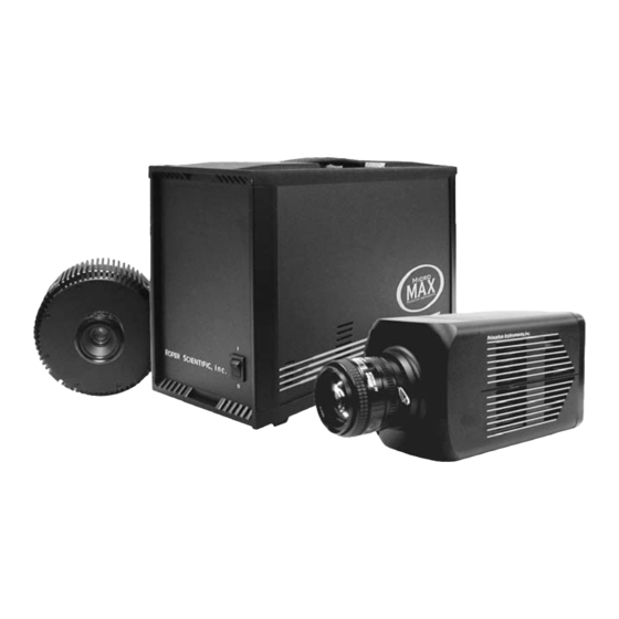
Surface mount electronic technology is used wherever possible, giving a compact package with uncompromising performance. Depending on your application, the camera included in your MicroMAX system will be either a compact round camera head or a high performance, cooled, rectangular camera head. -
Page 13: Controller
Applications With its small size, fully integrated design, cooled CCD and temperature control, advanced exposure control timing, and sophisticated readout capabilities, the MicroMAX system is well suited to both general macro imaging and microscopy applications. Computer Requirements Note: Computers and operating systems all undergo frequent revision. The following information is only intended to give an approximate indication of the computer requirements. -
Page 14: About This Manual
® Interface: PCI High-Speed Serial I/O card. Computers purchased from Roper Scientific as part of the MicroMAX system are shipped with the card installed. Computer Monitor: Super VGA monitor with 256 color graphics card and at least 512 kbytes of memory. -
Page 15: Safety Related Symbols Used In This Manual
Declarations of Conformity contains the Declarations of Conformity for 1 MHz (includes 100 kHz/1MHz) and 5 MHz MicroMAX systems. Warranty and Service provides the Roper Scientific warranty and customer support contact information. Safety Related Symbols Used in This Manual Caution! The use of this symbol on equipment indicates that one or more nearby items should not be operated without first consulting the manual. -
Page 16: Grounding And Safety
Never operate the camera cooled without proper evacuation or backfill. This could • damage the CCD! Never connect or disconnect any cable while the MicroMAX system is powered on. • Reconnecting a charged cable may damage the CCD. Never prevent the free flow of air through the equipment by blocking the air vents. -
Page 17: Cleaning
Do not allow any other material to touch the optical surfaces. Roper Scientific Customer Service Refer to the contact information located on page 150 of this manual. - Page 18 MicroMAX System User Manual Version 5.A This page intentionally left blank.
-
Page 19: Chapter 2 Installation Overview
Chapter 2 Installation Overview The list and diagrams below briefly describe the sequence of actions required to hookup your system and prepare to gather data. Refer to the indicated references for more detailed information. This list assumes that the application software is Princeton Instruments WinView/32. -
Page 20: Figure 2. Standard System Diagram
MicroMAX System User Manual Version 5.A Action Reference 11. If using a microscope Xenon or an Hg arc lamp, turn it on before Chapter 4 turning on the controller and host computer. Operation, page 33 12. Turn the Controller ON. -
Page 21: Chapter 3 System Setup
During the unpacking, check the system components for possible signs of shipping damage. If there are any, notify Roper Scientific and file a claim with the carrier. If damage is not apparent but camera or controller specifications cannot be achieved, internal damage may have occurred in shipment. -
Page 22: Power Requirements
Version 5.A Power Requirements The MicroMAX system can operate from any one of four different nominal line voltages, 100, 120, 220, or 240 V AC. The power consumption is nominally 200 watts and the line frequency can range from 47 to 63 Hz. -
Page 23: Mounting The Camera
Chapter 3 System Setup Mounting the Camera General The MicroMAX camera can be mounted either horizontally or vertically (nose up or nose down). The camera can rest on any secure surface. For mounting flexibility, the round head camera is equipped with four standard ¼″ x 20 UNC threaded 3/8″ deep holes spaced at 90°... -
Page 24: Mounting To A Microscope
MicroMAX System User Manual Version 5.A press the locking lever on the mount while rotating the lens clockwise until it comes free and can be pulled straight out. Both types of lenses typically have provision for focusing and aperture adjustment, with the details varying according the make and model of the lens. - Page 25 Chapter 3 System Setup C-Mount For a camera equipped with a C-mount thread, use the standard C-mount adapter supplied by the microscope manufacturer to attach the camera to the microscope. The adapter can be screwed into the camera and then the assembly can be secured to the microscope using the standard setscrews on the microscope.
-
Page 26: Figure 5. Bottom Clamps
F-mount nose. Roper Scientific DOES NOT advise using an F-mount to secure the camera to a bottom port of an inverted microscope due to possible failure of the locking mechanism of the F-mount. -
Page 27: Mounting To A Spectrometer
Chapter 3 System Setup HRP 100-NIK "L" bottom clamp Figure 6. Bottom Clamp secured to Relay Lens Caution Microscope optics have very high transmission efficiencies in the infrared region of the spectrum. Since typical microscope light sources are very good emitters in the infrared, some microscopes are equipped with IR blockers or heat filters to prevent heating of optical elements or the sample. -
Page 28: Installing The Application Software
Note: WinView/32 (versions 2.6.0 and higher) do not support the ISA interface. Installing the Interface Card If the computer is purchased from Roper Scientific, it will be shipped with the Serial Buffer card already installed. PCI Interface boards are standard. In the past, ISA had been supported but with WinView/32 versions 2.6.0 and higher, this support is no longer available. -
Page 29: Installing The Pci Card Driver
Chapter 3 System Setup To Install an ISA Serial Card: Support for ISA Serial boards has been discontinued as of the release of WinView/32 version 2.6.0. Earlier versions of the software still support this board. If you are using an earlier version of the WinView software and want to install an ISA card, contact the factory for instructions. -
Page 30: Selecting The Shutter Setting
25 mm Roper Scientific supplied External shutter (typically an Entrance slit shutter) 25 mm Roper Scientific Internal shutter 35 mm Roper Scientific Internal shutter (requires 70 V Shutter option) 40 mm Roper Scientific Internal shutter (supplied with LN camera having a 1340 × 1300 or larger CCD) * Shutter settings 0, 3, and 6-9 are unused and are reserved for future use. -
Page 31: Connecting The Detector-Controller Cable Or The Camera Power/Camera Signal Cables
Chapter 3 System Setup Connecting the Detector-Controller Cable or the Camera Power/Camera Signal Cables Turn the Controller power OFF (OFF = 0, ON = |) before connecting or disconnecting Caution the Detector-Controller cable or the Camera Power/Camera Signal Cables. To Connect the Detector-Controller Cable: 1. - Page 32 MicroMAX System User Manual Version 5.A This page intentionally left blank.
-
Page 33: Chapter 4 Operation
We advise that you place a clear warning sign on the power button of your arc lamp reminding all workers to follow this procedure. While Roper Scientific has taken great care to isolate its sensitive circuitry from EMF sources, we cannot guarantee that this protection will be sufficient for all EMF bursts. -
Page 34: Setting The Temperature
MicroMAX System User Manual Version 5.A enclosure of the camera. Fins on the round head camera shell radiate the heat outward to the surrounding atmosphere. The fan inside the rectangular head camera draws air through the vents in the camera shell, blows it through the internal fins, and exhausts it back into the atmosphere through the vents. -
Page 35: Imaging Field Of View
Chapter 4 Operation Imaging Field of View When used for two-dimensional imaging applications, the MicroMAX camera closely imitates a standard 35 mm camera. Since the CCD is not the same size as the film plane of a 35 mm camera, the field of view at a given distance is somewhat different. The imaging field of view is indicated in Figure 9. -
Page 36: Figure 10. Monitor Display Of Ccd Image Center Area
MicroMAX System User Manual Version 5.A Note: If more than one device is connected to the video output, the last device is the one that should to be terminated in 75Ω. For example, to connect the video output to a VCR as well as to a monitor, the cable from the controller video output should be connected to the video input connector of the VCR, and another 75 Ω... -
Page 37: First Light (Imaging)
Chapter 4 Operation Note: With a 16-bit A/D converter (not a standard option), the composite video output is disabled during data acquisition. In post-acquisition processing the WinView/32 ROI (Region of Interest) capability allows any portion of an acquired image to be displayed on the computer monitor. Again, note that the described video output behavior applies specifically for the WinView/32 software only. -
Page 38: Assumptions
MicroMAX System User Manual Version 5.A Camera-Controller Cable Assy. TAXI cable (Serial Com) 110/220 Camera Camera Camera Serial 110/220 Signal Controller Microscope Computer EXPERIMENT Figure 12. 5 MHz System Diagram Assumptions The following procedure assumes that 1. You have already set up your system in accordance with the instructions in Chapter 3. -
Page 39: Getting Started
Chapter 4 Operation described in Chapter 3. Be sure to secure both ends of the cable with the cable- connector screws. • Connect a 75 Ω BNC cable from the VIDEO connector on the back of the camera to the video monitor’s 75 Ω input. This cable must be terminated in 75 Ω. -
Page 40: Focusing
MicroMAX System User Manual Version 5.A Detector Temperature (Setup|Detector Temperature…): -15°C for round camera heads or -45°C for rectangular camera heads. The temperature should drop steadily, reaching the set temperature in about ten minutes (typical). At that point the green Temp Lock LED on the rear of the ST-133A will light and there will be a locked indication at the computer monitor, indicating that temperature lock has been established. - Page 41 Chapter 4 Operation Note: If you are using WinView/32 and a video monitor for focusing, select the mode from the Acquisition menu. Then select a short exposure Video Focus… time (0.1 s), an Intensity Scaling setting of 4096, and 2x Zoom. With an MicroMAX:1300Y camera (1030×1300 pixels), set the Pan selector as required for the 756×486 subset of the array image you wish to use for focusing purposes.
-
Page 42: Acquiring Data
Experiment Setup dialog box. (In WinView/32, you might want to begin with Free Run Asynchronous (Safe Mode) operation while gaining basic system familiarity.) This completes First Light for imaging applications. If the MicroMAX system functioned as described, you can be reasonably sure it has arrived in good working order. -
Page 43: Assumptions
Chapter 4 Operation it is possible to use a broadband source such as tungsten for the alignment. If this is the case, use a wavelength setting of 0.0 nm for alignment purposes. Assumptions The following procedure assumes that 1. You have already set up your system in accordance with the instructions in Chapter 3. -
Page 44: Focusing
MicroMAX System User Manual Version 5.A • Controller type: ST-133 • Controller version: 3 or higher • Camera type: Select the array installed in your detector. MicroMAX:512BFT = EEV 512×512 FT CCD57 MicroMAX:782Y = PID 582×782 MicroMAX:782YHS = PID 582×782 MicroMAX:1024B = EEV 1024×1024 CCD47_10... - Page 45 Chapter 4 Operation of focus and adjust for optimum while watching a live display on the monitor, followed by rotating the detector and again adjusting for optimum. The following procedure, which describes the focusing operation with an Acton 300I spectrograph, can be easily adapted to other spectrographs.
-
Page 46: Acquiring Data
Experiment Setup dialog box. (In WinSpec/32, you might want to begin with Free Run Asynchronous (Safe Mode) operation while gaining basic system familiarity.) This completes First Light for spectroscopy applications. If the MicroMAX system functioned as described, you can be reasonably sure it has arrived in good working order. -
Page 47: Chapter 5 Timing Modes
Chapter 5 Timing Modes The Princeton Instruments MicroMAX system has been designed to allow the greatest possible flexibility when synchronizing data collection with an experiment. The chart below lists the timing mode combinations. Use this chart in combination with the detailed descriptions in this chapter to determine the optimal timing configuration. -
Page 48: Standard Timing Modes
MicroMAX System User Manual Version 5.A sends the Stop Acquisition command to the camera, instructing it to stop acquisition. Once that frame is completely processed and displayed, another Start Acquisition command is sent from the computer to the camera, allowing it to take the next frame. -
Page 49: Figure 14. Chart Of Full Speed (Synchronous) And Safe (Asynchronous)
Chapter 5 Timing Modes Safe Mode (Asynchronous) Full Speed Mode (Synchronous) Start Start Computer programs Computer programs camera with exposure camera with exposure and binning parameters and binning parameters STARTACQ issued from STARTACQ issued from computer to camera computer to camera Cleans performed Cleans performed 1 frame collected... -
Page 50: External Sync
Figure 15. Free Run Timing Chart (part of the chart in Figure 14) Other experimental equipment can be synchronized to the MicroMAX system by using (NOTSCAN) signal. This TTL output for synchronous operation is shown in Figure 16. -
Page 51: Figure 17. Chart Showing Two External Sync Timing Options
Chapter 5 Timing Modes In the PreOpen Shutter mode, on the other hand, shutter operation is only partially synchronized to the experiment. As soon as the controller is ready to collect data the shutter opens. Upon arrival of the first External Sync pulse at the MicroMAX, the shutter remains open for the specified exposure period, closes, and the CCD is read out. -
Page 52: External Sync With Continuous Cleans
MicroMAX System User Manual Version 5.A Also note that, in addition to signal from ambient light, dark charge accumulates during the “wait” time (t ). Any variation in the external sync frequency also affects the amount of dark charge, even if light is not falling on the CCD during this time. -
Page 53: Frame Transfer Operation
Chapter 5 Timing Modes Note: If EXT SYNC is still active at the end of the readout, the hardware will interpret this as a second sync pulse, and so on. Open Close Open Close Open Close Shutter (Normal) Open Close Open Close Open... -
Page 54: Figure 21. Frame Transfer Where T W1 + T Exp + T C < T R
MicroMAX System User Manual Version 5.A low). More specifically, if the readout time, t , is greater than the sum of t , the time the controller waits for the first External Sync pulse, plus t , the programmed exposure time, plus t... -
Page 55: Interline Operation
Chapter 5 Timing Modes Shutter Monitor actual exposure time Scan External Sync (negative polarity shown) cleans acquisition Figure 22. Frame Transfer where t > t Shutter Monitor actual exposure time Scan External Sync (negative polarity shown) cleans acquisition Figure 23. Frame Transfer where Pulse arrives after Readout Interline Operation Operating Modes It is important to note that an interline chip can operate in either of two operating modes,... -
Page 56: Timing Options In Overlapped Readout Mode
MicroMAX System User Manual Version 5.A Non-overlapped: This operation mode is automatically selected by the • controlling software when the exposure time is less than the readout time. In non-overlapped operation, the image is transferred to the storage cells at the end of the exposure time and no further accumulation occurs (the imaging cells are switched off). -
Page 57: Figure 24. Overlapped Mode Where T W1 + T Exp + T C < T R
Chapter 5 Timing Modes counting of the programmed Exposure Time begins when the sync pulse arrives at the Ext Sync connector. The exposure ends on completion of the programmed Exposure Time. Then the data acquired during the first exposure is read out while the next frame of data is being acquired. -
Page 58: Figure 26. Overlapped Mode Where Pulse Arrives After Readout
MicroMAX System User Manual Version 5.A Shutter Monitor actual exposure time Scan External Sync (negative polarity shown) cleans acquisition Figure 26. Overlapped Mode where Pulse arrives after Readout... -
Page 59: Chapter 6 Exposure And Readout
Chapter 6 Exposure and Readout Before each image from the CCD array appears on the computer screen, it must first be read, digitized, and transferred to the computer. Figure 27 is a block diagram of the image-signal path. Incoming photons Controller Camera Up/down integrator... -
Page 60: Exposure With An Interline Array
MicroMAX System User Manual Version 5.A CCD arrays perform three essential functions: photons are transduced to electrons, integrated and stored, and finally read out. CCDs are very compact and rugged. Unintensified, uncoated CCDs can withstand direct exposure to relatively high light levels, magnetic fields and RF radiation. -
Page 61: Exposure With An Image Intensifier
Although the standard MicroMAX camera is not intensified, it is possible to connect it to a lens-coupled intensifier. Contact the factory if you are interested in more information about operating an intensified version of the MicroMAX system. Continuous Exposure (no shuttering) Unlike video rate CCD cameras, slow scan scientific cameras require a shutter to prevent “smearing”... -
Page 62: Saturation
MicroMAX System User Manual Version 5.A Interline For interline CCDs, image smearing may occur due to a small amount of light leaking through to the storage cells during the readout time. In the case of lens-coupled intensified cameras (ICCDs), this effect can be eliminated by using a fast phosphor and gating the intensifier at the same frame rate as the CCD. -
Page 63: Array Readout
Chapter 6 Exposure and Readout Array Readout In this section, a simple 6 × 4 pixel CCD is used to demonstrate how charge is shifted and digitized. As described below, two different types of readout are available. Full frame readout, for full frame CCDs, reads out the entire CCD surface at the same time. Frame transfer operation assumes half of the CCD is for data collection and half of the array is a temporary storage area. -
Page 64: Table 5. Approximate Readout Time For The Full-Frame Ccd Array
MicroMAX System User Manual Version 5.A digitized is the second column moved into the shift register. The order of shifting in our example is therefore D6, C6, B6, A6, D5, C5, B5, A5, D4..After charge is shifted out of each pixel the remaining charge is zero, meaning that the array is immediately ready for the next exposure. -
Page 65: Frame Transfer
Chapter 6 Exposure and Readout Frame Transfer The MicroMAX fully supports frame transfer readout. Operation in this mode is very similar to the operation of video rate cameras. Half of the CCD is exposed continuously, raising the exposure duty cycle to nearly 100%. The other half of the CCD is masked to prevent exposure, and it is here that the image is “stored”... -
Page 66: Interline
MicroMAX System User Manual Version 5.A Interline In this section, a simple 6 × 3 pixel interline CCD is used to demonstrate how charge is shifted and digitized. As described below, two different types of readout, overlapped and non-overlapped can occur. In overlapped operation, each exposure begins while the readout of the previous one is still in progress. -
Page 67: Figure 31. Overlapped Mode Exposure And Readout
Chapter 6 Exposure and Readout Empty Readout Register. Exposure Image has been shifted to storage cells, first has ended and image is being line has been shifted to Readout Register, transferred to storage cells. and second exposure begins. Charge from first cell has been After first image is read out,storage cells are shifted to the Output Node. -
Page 68: Figure 32. Non-Overlapped Mode Exposure And Readout
MicroMAX System User Manual Version 5.A Part 4 of Figure 32 illustrates the situation at the end of the readout. Both the imaging and storage cells are empty. In Free Run operation, the imaging cells will be switched back on immediately, allowing charge accumulation to begin. -
Page 69: Binning
Chapter 6 Exposure and Readout where is the smaller dimension of the CCD is the larger dimension of the CCD. is the time needed to shift one pixel out of the shift register is the time needed to digitize a pixel is the time needed to shift one line into the shift register CCD Array 1 MHz Readout... -
Page 70: Figure 33. 2 × 2 Binning For Full Frame Ccd
MicroMAX System User Manual Version 5.A render the camera photon shot noise limited, the S/N ratio improvement is roughly proportional to the square-root of the number of pixels binned. Figure 33 shows an example of 2 × 2 binning for a full frame CCD array. Each pixel of the image displayed by the software represents 4 pixels of the array. -
Page 71: Figure 34. 2 × 2 Binning For Interline Ccd
Chapter 6 Exposure and Readout On-Chip Binning for Interline Binning is the process of adding the data from adjacent cells together), and it can be accomplished in either hardware or software. Rectangular groups of cells of any size may be binned together, subject to some hardware and software limitations. Hardware binning is performed before the signal is read out by the preamplifier. -
Page 72: Digitization
MicroMAX System User Manual Version 5.A Software Binning One limitation of hardware binning is that the shift register pixels and the output node are typically only 2-3 times the size of imaging pixels as shown in Table 9. Consequently, if the total charge binned together exceeds the capacity of the shift register or output node, the data will be corrupted. - Page 73 Chapter 6 Exposure and Readout always be nosier than one designed for optimum noise performance. The MicroMAX camera can be provided with two analog converters, one optimized for high speed, the other for high precision, as a solution to this problem. For the most common system configurations, there will be a 1 MHz converter for the fastest possible data collection, and a 100 kHz converter for use where noise performance is the paramount concern.
- Page 74 MicroMAX System User Manual Version 5.A This page intentionally left blank.
-
Page 75: Chapter 7 Micromax Dif Camera (Double Image Feature)
Chapter 7 MicroMAX DIF Camera (Double Image Feature) Introduction This Appendix describes operation of the MicroMAX DIF system. Both the Controller and a MicroMAX Interline camera must have factory modifications installed for DIF operation. In addition to the internal changes, a camera modified for DIF operation would ordinarily include a mechanical shutter. -
Page 76: Timing Modes
MicroMAX System User Manual Version 5.A ESABI: Allows two fast images of equal duration to be acquired. Unlike the IEC and EEC modes, in the ESABI mode, two pulses are applied to the Ext. Sync. connector. Each initiates a separate acquisition, allowing the user to set the time between acquisitions by externally adjusting the time between the two applied pulses. -
Page 77: Figure 35. Free Run Mode Timing Diagram
Chapter 7 MicroMAX DIF Camera image. As soon as the first exposure actually begins, returns high, as shown in Figure 35. Thus the positive going edge of the output marks the start of the first exposure. In Free Run operation, the time that remains low will typically be in the range of 400 to 600 ns. -
Page 78: Iec (Internal Exposure Control)
MicroMAX System User Manual Version 5.A Summary of Free Run Timing mode Allows user to capture single images. • Requires that the switch, if present on the back of the camera, be set to INACTIVE. • Uses Exposure Time set via software Experiment Setup. -
Page 79: Figure 38. Timing Diagram For Typical Iec Measurement
Chapter 7 MicroMAX DIF Camera 200 ns EXT. SYNC. READY 1st Image 5 µs 2nd Image 5 µs Mechanical Shutter 8 ms 8 ms Figure 38. Timing Diagram for Typical IEC Measurement Figure 39 illustrates the interconnections that might be used for such an experiment with two lasers. -
Page 80: Eec (External Exposure Control)
MicroMAX System User Manual Version 5.A Example 2: As shown in Figure 41, the signal from the controller can be used to trigger the controller by connecting it back into the EXT SYNC connector. At the same time, it can be used to trigger a DG-535. -
Page 81: Esabi (Electronic Shutter Active Between Images)
Chapter 7 MicroMAX DIF Camera supplied by the user is required to initiate the imaging process and control the first image exposure time. The controller signal goes low when the camera is ready to begin imaging. Figure 42 illustrates an EEC timing example. READY EXT. -
Page 82: Tips And Tricks
MicroMAX System User Manual Version 5.A READY trig EXT. SYNC. (A) Signal Integration 1st Image 2nd Image Figure 43. ESABI Timing Example: Image Exposure time = t set in software Note: The input trigger pulse, t , must be shorter than the exposure time t . -
Page 83: Flatfield Correction
Chapter 7 MicroMAX DIF Camera controller as well as time-dependent (but constant for a fixed integration time) buildup of dark charge. The background subtract equation is: (Raw image data – Background) = Corrected image data. When background and flatfield operations are both performed, background subtraction is always performed first. - Page 84 MicroMAX System User Manual Version 5.A This page intentionally left blank.
-
Page 85: Chapter 8 Ttl Control
Chapter 8 TTL Control Introduction This connector provides 8 TTL lines in, 8 TTL lines out and an input control line. Figure 44 illustrates the connector and Table 11 lists the signal/pin assignments. Princeton Instruments WinView/32 software packages incorporate WinX32 Automation, a programming language that can be used to automate performing a variety of data acquisition and data processing functions, including use of the TTL IN/OUT functions. -
Page 86: Buffered Vs. Latched Inputs
MicroMAX System User Manual Version 5.A Table 10 illustrates this coding for decimal values 0 through 7. Obviously this table could easily be extended to show the coding for values all the way to 255. IN/OUT 8 IN/OUT 7 IN/OUT 6... -
Page 87: Ttl Diagnostics Screen
Chapter 8 TTL Control Pin # Assignment Pin # Assignment IN 1 IN 2 IN 3 IN 4 IN 5 IN 6 IN 7 IN 8 EN/CLK Reserved (future use) OUT 2 OUT 1 OUT 4 OUT 3 OUT 6 OUT 5 OUT 8 OUT 7... -
Page 88: Example
MicroMAX System User Manual Version 5.A • RG/58U coaxial cable. • Shielded Metalized hood (Radio Shack part no 276-1536A). • BNC connector(s) type UG-88 Male BNC connector (Radio Shack part no 278-103). Example Suppose you needed to build a cable to monitor the line TTL OUT 1. One approach would be to build a cable assembly as described in the following paragraphs. -
Page 89: Chapter 9 System Component Descriptions
Chapter 9 System Component Descriptions MicroMAX Camera CCD Array: MicroMAX offers a choice of CCD technologies to improve quantum efficiency (QE) and blue/green sensitivity. Arrays are available in full-frame, interline, and frame-transfer formats. Thinned, back- illuminated devices have a higher QE across the entire visible spectrum and far superior sensitivity in the blue/ green region than front-illuminated CCDs. - Page 90 MicroMAX System User Manual Version 5.A forced air. CCD temperature is controlled and monitored by via the host computer and the ST-133A Controller. Shutter: Rectangular head cameras are available with an internal 25 mm shutter. A shutter drive signal is available at the Remote shutter connector on the rear of the ST-133A Controller or on the rear of the camera.
- Page 91 Chapter 9 System Component Descriptions drawn into the camera by the internal fan and exhausted through the back panel. The fan is always in operation and air cooling of both the Peltier and the internal electronics takes place continuously. The fan is designed for low-vibration and does not adversely affect the image.
-
Page 92: St-133A Controller
MicroMAX System User Manual Version 5.A ST-133A Controller Electronics: The Model ST-133A is a compact, high performance CCD Camera Controller for operation with Princeton Instruments cameras. Designed for high speed and high performance image acquisition, the ST-133A offers data transfer at speeds up to 5 megapixel per second, standard video output for focusing and alignment. -
Page 93: Figure 46. St-133A Rear Panel
Chapter 9 System Component Descriptions The Analog/Control Module, which should always be located in the left-most slot, provides the following functions. • • Pixel A/D conversion Timing and synchronization of readouts • • CCD scan control Temperature control • • Exposure control Video output control The Interface Control Module, which should always be located in the center slot,... - Page 94 MicroMAX System User Manual Version 5.A The descriptions of the rear panel connectors that follow are keyed to Figure 46. Feature 1. Temperature Lock LED: Indicates that the temperature control loop has locked and that the temperature of the CCD array will be stable to within ± 0.05°C.
-
Page 95: Table 12. St-133A Shutter Drive Selection
Note that this selector may not be available on the 5 MHz controller. 14. Remote Shutter Connector: Provides shutter-hold pulses for a 25 mm Roper Scientific- supplied external shutter (typically an entrance slit shutter). Note that this selector may not be available on the 5 MHz controller. -
Page 96: Cables
MicroMAX System User Manual Version 5.A Selecting the wrong shutter setting will result in improper functioning of the shutter and WARNING may cause premature shutter failure. Shutter Scan = Exposure Time = Readout Time = Shutter Compensation Time Shutter Type... -
Page 97: Interface Card
). WinView/32 also features snap-ins and macro record functions to permit easy user customization of any function or sequence. PVCAM is the standard software interface for cooled CCD cameras from Roper Scientific. is a library of functions that can be used to control and acquire data from the camera when a custom application is being written. - Page 98 MicroMAX System User Manual Version 5.A This page intentionally left blank.
-
Page 99: Chapter 10 Troubleshooting
Chapter 10 Troubleshooting Do not attach or remove any cables while the MicroMAX system is powered on. WARNING! Introduction The following issues have corresponding troubleshooting sections in this chapter. Baseline Signal Suddenly Changes Page 100 Changing the ST-133A's Line Voltage and Fuses... -
Page 100: Baseline Signal Suddenly Changes
MicroMAX System User Manual Version 5.A Baseline Signal Suddenly Changes If you observe a sudden change in the baseline signal, you may have excessive humidity in the vacuum enclosure of the camera. Turn off the controller and have the camera repumped before resuming normal operation. -
Page 101: Controller Is Not Responding
Chapter 10 Troubleshooting Controller Is Not Responding If this message pops up when you click on OK after selecting the "Interface Type" during Hardware Setup (under the WinView/32 Setup menu), the system has not been able to communicate with the Controller. Check to see if Controller has been turned ON and if the interface card, its driver, and the interface cable have been installed. -
Page 102: Detector Loses Temperature Lock
Detector Stops Working Problems with the host computer system or software may have side effects that appear to be hardware problems. If you are sure the problem is in the MicroMAX system hardware, begin with these simple checks: • Turn off all AC power. -
Page 103: Error Occurs At Computer Powerup
Chapter 10 Troubleshooting Error occurs at Computer Powerup If an error occurs at boot up, either the interface card is not installed properly or there is an address or interrupt conflict. Turn off the computer, reinstall the interface card (make sure it is firmly seated), and reboot the system. - Page 104 Most often, all that's required is a program that will read and report the address and interrupt assignments for each PCI device in the computer. One such program available from Roper Scientific's Technical Support department is called PCICHECK. When the program is run, it reports the address and interrupt assignments for the first PCI device it finds.
-
Page 105: Removing/Installing A Plug-In Module
Chapter 10 Troubleshooting bus arbitration scheme assures that, as long as every PCI card conforms to the PCI guidelines, the on-board memory will never overflow. Unfortunately, there are some PCI peripheral cards that do not fully conform to the PCI guidelines and that take control of the bus for longer periods than the PCI specification allows. -
Page 106: Shutter Malfunctions
MicroMAX System User Manual Version 5.A To Remove a Module: Verify that the Controller has been turned OFF. Rotate the two locking screws (one at the top of the module and one at the bottom) counterclockwise until they release from the chassis. -
Page 107: Appendix A Specifications
Appendix A Specifications CCD Arrays Spectral Range Typically: 370-900 for MicroMAX:512BFT and 1024B 400-1000 for MicroMAX:782Y, 782YHS 300-1080 for MicroMAX:1300Y, 1300YHS, and 1300YHS-DIF Types The following list is not necessarily current. Other chips may also be available. Contact the factory for up-to-date information. Model CCD (WinView/32 Pixel Format... -
Page 108: Temperature Control
Shutter Shutter Compensation Time None 200 nsec Electronic 6.0 msec Remote (Roper Scientific supplied 23 mm) 8.0 msec Small (Roper Scientific supplied 25 mm) 8.0 msec Large (Roper Scientific supplied 35 mm) 28.0 msec The 35 mm shutter requires a controller having the 70 V shutter drive modification. Controllers... -
Page 109: Inputs
Appendix A Specifications Inputs EXT SYNC: TTL input (BNC) to allow data acquisition to be synchronized with external events. Sense can be positive or negative going as set in software. Synchronization and Trigger Modes are discussed in Chapter 5. Outputs VIDEO: 1 V pk-pk from 75 Ω, BNC connector. -
Page 110: Miscellaneous
MicroMAX System User Manual Version 5.A Memory (RAM): Minimum of 32 Mbytes; possibly more depending on experiment design and size of CCD Array. Operating System: Windows 95/ME/2000/XP or Windows NT for WinView/32. Windows 3.1 required for 16- bit versions of WinView. -
Page 111: Appendix B Outline Drawings
Appendix B Outline Drawings 8.75 Figure 51. ST-133A Controller Dimensions... -
Page 112: Figure 52. Rectangular Camera Head: C-Mount
MicroMAX System User Manual Version 5.A C-MOUNT (1.00-32 THREAD) 4.63 4.63 0.500 COOLING AIR INLET TYPICAL BOTH SIDES OPTIONAL TRIPOD COOLING AIR OUTLET MOUNT KIT TYPICAL BOTH SIDES (2550-0312) DB-25 MALE GAIN SWITCH ACCESS TO CONTROLLER 2.41 2.25 3.16 0.94 1.14... -
Page 113: Figure 53. Rectangular Camera Head: F-Mount
Appendix B Outline Drawings F-MOUNT (2 3/8” - 20 THREAD NIKON ADAPTER SHOWN 4.63 4.63 NIKON F-MOUNT 0.50 COOLING AIR INLET TYPICAL BOTH SIDES COOLING AIR OUTLET OPTIONAL TRIPOD TYPICAL BOTH SIDES MOUNT KIT (2550-0312) DB-25 MALE GAIN SWITCH ACCESS TO CONTROLLER 3.16 0.94... -
Page 114: Figure 54. Rectangular Camera Head: Spectroscopy Mount With Shutter
MicroMAX System User Manual Version 5.A Figure 54. Rectangular Camera Head: Spectroscopy Mount with Shutter... -
Page 115: Figure 55. Rectangular Camera Head: Spectroscopy Mount Without Shutter
Appendix B Outline Drawings Figure 55. Rectangular Camera Head: Spectroscopy Mount without Shutter... -
Page 116: Figure 56. 1 Mhz And 100Khz/1Mhz Round Head Camera: C-Mount Adapter And Shutter
MicroMAX System User Manual Version 5.A Figure 56. 1 MHz and 100kHz/1MHz Round Head Camera: C-Mount Adapter and Shutter... -
Page 117: Figure 57. 5 Mhz Round Head Camera: C-Mount Adapter
Appendix B Outline Drawings Figure 57. 5 MHz Round Head Camera: C-Mount Adapter... -
Page 118: Figure 58. 1 Mhz Round Head Camera: F-Mount Adapter
MicroMAX System User Manual Version 5.A Figure 58. 1 MHz Round Head Camera: F-Mount Adapter... -
Page 119: Appendix C Kinetics Mode
Appendix C Kinetics Mode Introduction Kinetics mode uses the CCD to expose and store a limited number of images in rapid succession. The time it takes to shift each line (or row) on the CCD is as short as a few hundred nanoseconds to few microseconds, depending on the CCD. -
Page 120: Kinetic Timing Modes
MicroMAX System User Manual Version 5.A Kinetic Timing Modes Kinetics mode operates with three timing modes: Free Run, Single Trigger, and Multiple Trigger. Figure 60. Hardware Setup dialog box Figure 61. Experiment Setup dialog box Free Run In the Free Run Kinetics mode, the controller takes a series of images, each with the Exposure time set through the software (in WinView32, the exposure time is set on the Experiment Setup|Main tab page). -
Page 121: Single Trigger
Appendix C Kinetics Mode START ACQUIRE command from the software issent automatically when ACQUIRE or FOCUS is clicked on in the software. START ACQUIRE Exposure Shutter Monitor Signal Shift Shutter Shutter opening closing time time Readout Not SCAN Signal Figure 62. Free Run Timing Diagram Single Trigger Single Trigger Kinetics mode takes an entire series of images with each External Trigger Pulse (applied at the Ext. -
Page 122: Figure 64. Multiple Trigger Timing Diagram
MicroMAX System User Manual Version 5.A START ACQUIRE command from the software issent automatically when ACQUIRE or FOCUS is clicked on in the software. START ACQUIRE External Triggers Exposure Shutter Monitor Signal Shift Shutter Shutter opening closing time time Readout Not SCAN Signal Figure 64. -
Page 123: Appendix D Virtual Chip Mode
Appendix D Virtual Chip Mode Introduction Virtual Chip mode (a WinView/32 option) is a special fast-acquisition technique that allows frame rates in excess of 100 fps to be obtained. For the Virtual Chip selection to be present, it is necessary that: •... -
Page 124: Virtual Chip Setup
MicroMAX System User Manual Version 5.A The table below shows the minimum exposure time per frame (msec/Frame) and the number of frames per second (FPS) for several ROIs. Note that these numbers are provided for the 1 MHz and the 100 kHz readout rates. -
Page 125: Assumptions
Appendix D Virtual Chip Mode Assumptions: • You are familiar with the WinView/32 software and have read the hardware manuals. • Masking is for a 47x47 pixel Virtual Chip with its origin at 1,1. System Connection Diagram: Detector-Controller TAXI cable (Serial Com) 110/220 Camera... - Page 126 X direction. However, the set of choices for the Y-dimension has been pre- selected for optimal performance. Note that the origin point that Roper Scientific uses for a CCD array is 1,1. •...
- Page 127 Appendix D Virtual Chip Mode 11. Click on the Load Default Values button. This enters the default ROI values. These values are: Start pixels of 1,1; End pixels based on the Chip Y and Chip X dimensions; and Groups of 1. •...
-
Page 128: Experimental Timing
MicroMAX System User Manual Version 5.A Experimental Timing Triggering can be achieved through the software via the timing mode Software Trigger (selectable on the dialog box, tab page) or it can be Experiment Setup Timing Mode achieved via the input on the rear of the camera. Triggering from the... -
Page 129: Tips
Appendix D Virtual Chip Mode Load Default Values: Fills in the region of interest X and Y End values based on the Chip X and Y Dimension entries. By default, the ROI origin is at 1,1 and the Group values are both 1. Download Virtual Chip Definition: Sends the virtual chip parameter values to the controller’s non-volatile memory. - Page 130 MicroMAX System User Manual Version 5.A This page intentionally left blank.
-
Page 131: Appendix E Repumping The Vacuum
Troubleshooting on page 101). Notes: 1. To minimize outgassing, all Roper Scientific detectors are vacuum baked at the factory. Nevertheless, new detectors will experience a higher outgassing rate than detectors that have been in operation for several months, and are more likely to require repumping. -
Page 132: Vacuum Pumpdown Procedure
MicroMAX System User Manual Version 5.A Figure 68. Vacuum Connector Required for Pumping • Phillips screwdriver and a 3/16" nut driver, required to remove the back plate from the camera. Vacuum Pumpdown Procedure The instructions that follow are for a 1 MHz or 100kHz/1 MHz round head camera only. -
Page 133: Figure 70. Attaching The Vacuum Connector
Appendix E Repumping the Vacuum 7. Remove the vacuum system from the Vacuum Connector. While turning the top knob counterclockwise, remove the Vacuum Connector from the camera. Replace the back cover. Figure 70. Attaching the Vacuum Connector Figure 71. Opening the Camera to the Vacuum System... - Page 134 MicroMAX System User Manual Version 5.A This page intentionally left blank.
-
Page 135: Appendix F Spectrometer Adapters
Appendix F Spectrometer Adapters Roper Scientific offers a variety of spectrometer adapters for rectangular head (NTE) MicroMAX systems. The mounting instructions for these adapters are organized by spectrometer model, camera type, and adapter kit number. The table below cross- references these items with the page number for the appropriate instruction set. -
Page 136: Chromex 250 Is (Nte With Or Without Shutter)
MicroMAX System User Manual Version 5.A Chromex 250 IS (NTE with or without shutter) Description 2517-0901 Plate, Adapter-Female Screw, 10-32 × 3/4, Socket head, Stainless Steel, Hex, Black 2826-0283 2518-0107 Adapter-Male, HR320 Screw, 10-32 × 1/4, Button Head Allen Hex, Stainless Steel 2826-0127 Set Screw, 10-32 ×... -
Page 137: Isa Hr 320 (Nte With Or Without Shutter)
Appendix F Spectrometer Adapters ISA HR 320 (NTE with or without shutter) Remove spectrometer cover for these screws. Description 2518-0106 Adapter-Female, HR320 2826-0087 Screw, M5-10, Flat Head, Socket, Stainless Steel 2518-0107 Adapter-Male, HR320 Screw, 10-32 × 1/4, Button Head Allen Hex, Stainless Steel 2826-0127 Set Screw, 10-32 ×... -
Page 138: Isa Hr 640 (Nte With Or Without Shutter)
MicroMAX System User Manual Version 5.A ISA HR 640 (NTE with or without shutter) Description 2518-0203 Adapter-Female, HR640 Screw, M4-.7 × 14, Socket Head Cap, Stainless Steel 2826-0144 2518-0107 Adapter-Male, HR320 Screw, 10-32 × 1/4, Button Head Allen Hex, Stainless Steel 2826-0127 Set Screw, 10-32 ×... -
Page 139: Jy Triax Family (Nte Without Shutter)
Appendix F Spectrometer Adapters JY TRIAX family (NTE without shutter) Flanged Spectrometer Mount Remove 4 screws Description 2518-1000 Adapter, TRIAX, NTE, 7377, 7376, 7413 Screw, 10-32 × 5/8, Socket Head, Stainless Steel, Hex, Black 2826-0191 Typically, the adapter is shipped already mounted to the camera. The following procedure is provided in case you have ordered a JY TRIAX adapter for a shutterless MicroMAX rectangular head (NTE) camera that you already own. -
Page 140: Spex 270M (Nte With Or Without Shutter)
MicroMAX System User Manual Version 5.A SPEX 270M (NTE with or without shutter) Description 2518-0691 Female Adapter Plate, 2.400 ID Screw, 6-32 × 3/8, Socket Head, Cap, Stainless Steel 2826-0068 2518-0690 Adapter, Focusing, Male, Spec 270 Screw, 10-32 × 1/4, Button Head Allen Hex, Stainless Steel 2826-0127 Screw 6-32 ×... -
Page 141: Spex 500M (Nte With Or Without Shutter)
Appendix F Spectrometer Adapters SPEX 500M (NTE with or without shutter) Description 2517-0214 Adapter-Female, Spex 500m Screw, 1/4-20 × 0.51, Low Socket Head Cap, Black 2826-0170 2518-0223 Adapter-Male, Spex 500m Screw, 10-32 × 1/4, Flat Head Slot, Stainless Steel 2826-0134 Screw, 8-32 ×... -
Page 142: Spex Triplemate (Nte With Or Without Shutter)
MicroMAX System User Manual Version 5.A SPEX TripleMate (NTE with or without shutter) Description 2518-0184 Adapter-Male, LN/TE, CCD/For Spex TripleMate Screw, 10-32 × 5/8, Socket Head Cap, Stainless Steel, 2826-0128 2517-0163 Slit Mount, Spex Screw, 1/4-20 × 3/4, Socket Head Cap, Stainless Steel 2826-0129 Screw, 10-32 ×... -
Page 143: Declarations Of Conformity
Declarations of Conformity This section of the MicroMAX manual contains the declarations of conformity for MicroMAX systems. MicroMAX systems encompass RTE (round thermoelectrically-cooled) and NTE (rectangular thermoelectrically-cooled) camera heads and their associated controllers. -
Page 144: Mhz Round Head (Rte) Systems
ROPER SCIENTIFIC (PRINCETON INSTRUMENTS) 3660 QUAKERBRIDGE ROAD TRENTON, NJ 08619 Declare under our sole responsibility, that the product MicroMAX SYSTEM With RTE/CCD CAMERA, To which this declaration relates, is in conformity with general safety requirement for electrical equipment standards: IEC 1010-1:1990, EN 61010-1:1993/A2:1995... -
Page 145: Mhz Round Head (Rte) Systems
DECLARATION OF CONFORMITY ROPER SCIENTIFIC (PRINCETON INSTRUMENTS) 3660 QUAKERBRIDGE ROAD TRENTON, NJ 08619 Declare under our sole responsibility, that the product ST-133A 5MHz CONTROLLER With RTE CAMERA HEAD, To which this declaration relates, is in conformity with general safety requirement for electrical... -
Page 146: Mhz Rectangular Head (Nte) Systems
DECLARATION OF CONFORMITY We, , ROPER SCIENTIFIC (PRINCETON INSTRUMENTS) 3660 QUAKERBRIDGE ROAD TRENTON, NJ 08619, Declare under our sole responsibility that the product ST-133A 1 MHz HIGH POWER CONTROLLER w/NTE CAMERA HEAD, To which this declaration relates, is in conformity with general safety requirement for electrical... -
Page 147: Warranty & Service
Roper Scientific warrants this product against substantial defects in materials and / or workmanship for a period of up to one (1) year after shipment. During this period, Roper Scientific will repair the product or, at its sole option, repair or replace any defective part without charge to you. -
Page 148: Versarray (Xp) Vacuum Chamber Limited Lifetime Warranty
Limited One (1) Year Warranty. Vacuum Integrity Limited 24 Month Warranty Roper Scientific warrants the vacuum integrity of all our products for a period of up to twenty-four (24) months from the date of shipment. We warrant that the detector head will maintain the factory-set operating temperature without the requirement for customer pumping. -
Page 149: Owner's Manual And Troubleshooting
(1) year limited warranty and/or any other warranty, expressed or implied. 3. All warranty service must be made by the Roper Scientific factory or, at our option, an authorized service center. 4. Before products or parts can be returned for service you must contact the Roper Scientific factory and receive a return authorization number (RMA). -
Page 150: Contact Information
In no event shall Roper Scientific’s liability exceed the cost of the repair or replacement of the defective product or part. -
Page 151: Index
Index Camera (cont.) 64-pin DIN connector 92, 106 introduction to A/D converters mounting considerations dual 1/4" x 20 UNC threaded holes specifications orientation constraints AC power requirements use of mounting bracket for security23 Accessories, alignment of Cautions Actual exposure time 53, 56 baseline signal shift 34, 100... - Page 152 MicroMAX System User Manual Version 5.A Connectors (cont.) Exposure (cont.) ST-133A, Serial COM shutter ST-133A, TTL In/Out 87, 94 Exposure and Readout ST-133A, Video Output Exposure time Contact information actual 53, 56 Continuous Cleans. programmed 53, 56 Cooling External shutter...
- Page 153 Index Free Run (cont.) MicroMAX system timing diagram applications timing flow-chart camera Full frame readout camera cooling system Full Speed (Asynchronous) mode CCD array Full Speed (Synchronous) mode components of data acquisition controller image update lag data conversion Fuse replacement, ST-133A...
- Page 154 MicroMAX System User Manual Version 5.A Pan function S/N ratio 62, 72 Parfocality Safe (Asynchronous) mode PCI card driver installation as used for setting up PCI serial interface card fast image update diagnostics software missed events driver installation Saturation non-conforming peripheral cards...
- Page 155 Index ST-133A Controller (cont.) Virtual Chip mode zero adjustment setup Synchronous vs Asynchronous flow chart49 software option WXvchip.opt file Technical support Temperature Warnings control cleaning problems Controller/Camera cable specifications fuse type effect of vacuum deterioration module installation/removal under power92, lock LOCK indicator LED opening the power input module operating environment...
- Page 156 MicroMAX System User Manual Version 5.A This page intentionally left blank.
- Page 157 Note: If you have a PI-MAX system with a Programmable Timing Generator (PTG) module installed in the ST-133A and are changing from one interface type to another (TAXI to USB 2.0 or USB 2.0 to TAXI), contact Roper Scientific Technical Support for specific installation instructions. See page 13 for contact information...
- Page 158 Large data sets and/or long acquisition times may be subject to data overrun because of host computer interrupts during data acquisition. • The Roper Scientific PC Interface Library (EasyDLLS) does not support USB 2.0. • Some WinX (WinView and WinSpec) 2.5.X features are not fully supported with USB 2.0.
- Page 159 On the Select Components dialog box (see Figure 1), click on the AUTO PCI button to install the interface card drivers (PCI and the Roper Scientific USB drivers) and the Figure 1. WinView Installation: Interface Card Driver most commonly installed program Selection files.
- Page 160 According to the window text, the hardware associated with the driver will not work until you restart the computer. June 17, 2003 4 of 14 Roper Scientific E:\Manuals\USB 2.0 Installation\USB Addendum to Manual.doc...
- Page 161 INF files required to support the USB 2.0 Interface Control module. 1. Before installing the Roper Scientific USB2 Interface, we recommend that you defragment the host computer's hard disk. This operation reduces the time the computer spends locating files. Typically, the "defrag" utility "Disk Defragmenter"...
- Page 162 . Data transfer will be disabled if this box is left unchecked 4. Run the software in focus mode to verify communication between the ST-133A and the host computer. June 17, 2003 6 of 14 Roper Scientific E:\Manuals\USB 2.0 Installation\USB Addendum to Manual.doc...
-
Page 163: Troubleshooting
If your experiment requirements include long data acquisition times and/or large data sets, your application may not be suitable for the USB 2.0 interface. Therefore, we recommend replacement of the USB 2.0 interface module with our Roper Scientific 7 of 14 June 17, 2003... - Page 164 USB 2.0 Interface Addendum TAXI interface module and Roper Scientific PCI card. If this is not the case and data overruns continue to occur, contact Technical Support (see page 13 for contact information). Demo is only Choice on Hardware Wizard:Interface dialog If RSConfig.exe has not been run and there is not an installed Roper Scientific high speed PCI...
- Page 165 Demo, High Speed PCI, and PCI(Timer) are Choices on Hardware Wizard:Interface dialog If there is an installed Roper Scientific high speed card in the host computer and you want to operate a camera using the USB 2.0 interface, the PVCAM.INI file (created by RSConfig.exe) must exist and the USB 2.0 supported camera must be [Camera_1].
- Page 166 Next and continue through the Wizard. After the Wizard is finished, the Controller/Camera tab card will be displayed with the Use PVCAM checkbox selected. You should now be able to acquire data. June 17, 2003 10 of 14 Roper Scientific E:\Manuals\USB 2.0 Installation\USB Addendum to Manual.doc...
- Page 167 3. If the ST-133A is connected and on, the USB 2.0 camera may not be listed as Camera 1 in the PVCAM.INI file. 4. Run RSConfig.exe (accessible from the Windows|Start|Programs|Roper Scientific menu). If the USB 2.0 camera is listed as Camera 2 (Princeton Style (USB2) in Figure 10), you will have to edit the PVCAM.INI file.
- Page 168 OK, turn on the ST-133A, and, on the PVCAM dialog box, make sure Yes is selected and then click on Next. The Hardware Wizard should continue to the Controller Type dialog box. June 17, 2003 12 of 14 Roper Scientific E:\Manuals\USB 2.0 Installation\USB Addendum to Manual.doc...
- Page 169 January 2001. Earlier versions of the ST-133 did not contain non- volatile RAM (NVRAM), which is programmed with information about the controller and the camera. PVCAM, the program under which the Roper Scientific USB works, retrieves the information stored in NVRAM so it can enter specific camera characteristics into WinView/32 or WinSpec/32.
- Page 170 USB 2.0 Interface Addendum This page intentionally left blank. June 17, 2003 14 of 14 Roper Scientific E:\Manuals\USB 2.0 Installation\USB Addendum to Manual.doc...
Need help?
Do you have a question about the MicroMAX System and is the answer not in the manual?
Questions and answers