Table of Contents
Advertisement
Quick Links
Advertisement
Table of Contents
Troubleshooting

Related Manuals for Princeton Instruments PI-MAX System


Summary of Contents for Princeton Instruments PI-MAX System
- Page 1 4411-0069 Version 5.F September 9, 2009 *4411-0069*...
- Page 2 The information in this publication is believed to be accurate as of the publication release date. However, Princeton Instruments does not assume any responsibility for any consequences including any damages resulting from the use thereof. The information contained herein is subject to change without notice.
-
Page 3: Table Of Contents
Table of Contents Attention! ......................xv Chapter 1 Introduction ..................17 PI-MAX System Components ..................17 Camera Head ......................17 ST-133 Controller ...................... 18 Cables ......................... 18 Summary of PI-MAX Data Acquisition ................19 Safety Information ......................20 Safety Related Symbols Used in This Manual ............20 Grounding and Safety .................... - Page 4 PI-MAX/PI-MAX2 System Manual Version 5.F ® TAXI Cable (6050-0148-CE) ................... 42 USB 2.0 Cable (6050-0494) ..................42 Connecting the Detector-Controller Cable ............... 42 Connecting to the Timing Generator ................43 PTG ..........................43 DG535 ........................43 Making the Coolant Circulator-Camera Connections ............44 Entering the Default Camera System Parameters into WinX (WinView/32, WinSpec/32, or WinXTest/32) ..................
- Page 5 Table of Contents Digitization ........................67 Experiment Setup|Main ....................67 Exposure Time ......................67 Number of Images/Spectra and Accumulations ............68 CCD Readout ......................68 Amplifier ........................68 Intensifier Gain ......................68 Intensifier Mode ......................68 Experiment Setup|Timing ....................69 Timing Mode ......................
- Page 6 PI-MAX/PI-MAX2 System Manual Version 5.F Procedure for Setting up and Performing a Swept Gate Experiment (Fixed Width, Variable Delay) ....................93 Procedure for Setting up and Performing a Single Shot Experiment ....... 102 Procedure for Setting up and Performing a Swept Gate Experiment (Variable Width, Variable Delay): ...................
- Page 7 Table of Contents Single Trigger Mode ....................130 Dual Trigger Mode ....................131 Setup ..........................132 Hardware ........................132 Software ........................132 Operation ........................132 Single Trigger Mode ....................132 Dual Trigger Mode ....................133 Tips and Tricks ....................... 134 Chapter 11 Tips and Tricks ................
- Page 8 viii PI-MAX/PI-MAX2 System Manual Version 5.F TTL Out .......................... 150 TTL Diagnostics Screen ....................151 Hardware Interface ......................151 Example ........................152 Chapter 14 System Component Descriptions ..........153 Introduction ........................153 PI-MAX Camera ......................153 Mount Adapters ......................153 Switches, Connectors and Indicators ................
- Page 9 Table of Contents Operating Environment ....................186 Controller ........................186 Internal Pulser ......................... 188 Appendix B Outline Drawings ................ 189 PI-MAX/PI-MAX2 ......................189 ST-133A Controller ......................190 ST-133B Controller ......................191 Appendix C Software ..................193 Introduction ........................193 Camera State ........................193 Main tab page (Experiment Setup on Acquisition menu) ..........
- Page 10 Figure 12. RSConfig dialog box ..................46 Figure 13. Hardware Setup wizard: PVCAM dialog box ..........46 Figure 14. Block Diagram of Signal Path in Standard PI-MAX System ......53 Figure 15. Clean Cycles in Free Run Operation .............. 55 Figure 16.
- Page 11 Table of Contents Figure 30. Timing Diagram: Internal Sync (PTG) ............78 Figure 31. Timing Diagram: Internal Sync with an External Trigger ......78 Figure 32. PTG Fast Gating Experiment Block diagram ..........84 Figure 33. Fast Gating Measurement Results ..............84 Figure 34.
- Page 12 PI-MAX/PI-MAX2 System Manual Version 5.F Figure 79. Timing Diagram: Experiment 1 ..............127 Figure 80. Timing Diagram: Experiment 2 ..............128 Figure 81. DIF Operation: Single Trigger Timing Diagram .......... 130 Figure 82. DIF Operation: Dual Trigger Timing Diagram ..........131 Figure 83.
- Page 13 Table of Contents xiii Tables Table 1. PCI Driver Files and Locations ................. 39 Table 2. USB Driver Files and Locations ................ 42 Table 3. Readout Rates for Kodak 1024 × 1024 Array at 5 MHz ........64 Table 4. Timing Mode, Shutter Control, Ext. Trigger Input for Shutter Mode ....74 Table 5.
- Page 14 PI-MAX/PI-MAX2 System Manual Version 5.F This page intentionally left blank.
-
Page 15: Attention
Attention! Intensified CCD detectors, such as the PI-MAX, when biased ON, can be irreparably WARNING damaged if continuously exposed to light levels higher than twice the A/D saturation level. Thus it is critical that you not establish conditions that could result in damage to the intensifier. - Page 16 PI-MAX/PI-MAX2 System Manual Version 5.F This page intentionally left blank.
-
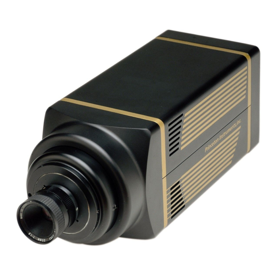
Page 17: Chapter 1 Introduction
Cooling within the camera head is performed by a cooling fan and a Figure 1. Typical Standard PI-MAX System Components multi-stage Peltier cooler that is thermally coupled to the CCD (liquid coolant circulation can also be used for the standard PI-MAX camera). -
Page 18: St-133 Controller
TAXI: 6050-0148-CE, 25 foot/7.6 meter or USB 2: 6050-0494, 16.4 foot/5 meter. Not supported by PI-MAX2. Computer Interface Card : Princeton Instruments High Speed PCI card or user- provided USB 2.0 interface card. Manuals: PI-MAX System manual and optional application software manual. -
Page 19: Summary Of Pi-Max Data Acquisition
Chapter 1 Introduction Summary of PI-MAX Data Acquisition Figure 2. Major Components of the Intensifier-CCD In the PI-MAX camera, the input image is focused onto the photocathode of an image intensifier tube. The tube electronically amplifies the image and outputs it, much brighter, as gray-scaled green light. -
Page 20: Safety Information
PI-MAX/PI-MAX2 System Manual Version 5.F 3. Since the voltage at the MCP output is much more positive, most of the electrons accelerate into the MCP channels and, if they hit the channel walls, will generate additional electrons, resulting in electron gain. The amount of gain is adjusted by increasing or decreasing the voltage at the MCP output. -
Page 21: Grounding And Safety
Chapter 1 Introduction Grounding and Safety The ST-133 is of Class I category as defined in IEC Publication 348 (Safety Requirements for Electronic Measuring Apparatus). It is designed for indoor operation only. Before turning on the controller, the ground prong of the powercord plug must be properly connected to the ground connector of the wall outlet. -
Page 22: High Intensity Light Damage
Never operate the camera cooled without proper evacuation or backfill. This could damage the CCD! Never connect or disconnect any cable while the PI-MAX system is powered on. Reconnecting a charged cable may damage the CCD. Never prevent the free flow of air through the equipment by blocking the air vents. -
Page 23: Cleaning Optical Surfaces
232 for contact information. Repairs Save the original packing materials. Because the PI-MAX system contains no user- serviceable parts, repairs must be done by Princeton Instruments. Should your system need repair, contact Princeton Instruments customer support for instructions (telephone, e-mail, and address information are provided on page 232 of this manual). -
Page 24: Manual Organization
PI-MAX system in gate mode with an installed PTG. Chapter 8, Gated Operation with a DG535 discusses issues specific to operating the PI-MAX system in gate mode with a Stanford Research DG535. Chapter 9, Kinetics Operation describes the Kinetics option and includes example experiments. - Page 25 Appendix H, Glossary provides definitions of commonly used words and terms related to intensified camera characteristics and usage. Declarations of Conformity contains the Declarations of Conformity for PI-MAX systems. Warranty & Service details the warranties for Princeton Instruments equipment and software.
- Page 26 PI-MAX/PI-MAX2 System Manual Version 5.F This page intentionally left blank.
-
Page 27: Chapter 2 Installation Overview
Chapter 2 Installation Overview The list and diagrams below briefly describe the sequence of actions required to install your system and prepare to gather data. Refer to the indicated references for detailed information. Action Reference 1. If the system components have not already been unpacked, unpack Chapter 3 System Setup, them and inspect their carton(s) and the system components for in- page 33... - Page 28 PI-MAX/PI-MAX2 System Manual Version 5.F Action Reference 13. Turn the Controller ON. 14. Turn on the computer and begin running the WinX application. Chapter 3 System Setup, When the computer boots, you may be asked for the location of the page 38 (PCI drivers), interface drivers.
-
Page 29: Figure 3. Pi-Max With Ptg System Diagram
Chapter 2 Installation Overview Figure 3. PI-MAX with PTG System Diagram Figure 4. PI-MAX2 with PTG System Diagram... -
Page 30: Figure 5. Gen Ii Pi-Max With Dg535 System Diagram
PI-MAX/PI-MAX2 System Manual Version 5.F Figure 5. Gen II PI-MAX with DG535 System Diagram Figure 6. Gen II PI-MAX2 with DG535 System Diagram... -
Page 31: Figure 7. Gen Iii Pi-Max With Dg535 System Diagram
Chapter 2 Installation Overview Figure 7. Gen III PI-MAX with DG535 System Diagram Figure 8. Gen III PI-MAX2 with DG535 System Diagram... - Page 32 PI-MAX/PI-MAX2 System Manual Version 5.F This page intentionally left blank.
-
Page 33: Chapter 3 System Setup
During unpacking, check the system components for possible signs of shipping damage. If there are any, notify Princeton Instruments and file a claim with the carrier. Be sure to save the shipping carton for inspection by the carrier. If damage is not apparent but system specifications cannot be achieved, internal damage may have occurred in shipment. -
Page 34: System Requirements
PI-MAX: DB25 to DB25 cable. Standard length is 15 ft (6050-0336). PI-MAX2: Cable set, 15 ft (6050-0499) Computer Interface: TAXI or USB 2.0. Computer: Can be purchased from Princeton Instruments or provided by user. WinView/WinSpec CD-ROM User Manuals ... -
Page 35: Power
XP operating system. High speed PCI serial card (or an unused PCI card slot). Computers purchased from Princeton Instruments are shipped with the PCI card installed if High speed PCI was ordered. Minimum of 32 Mbytes of RAM for CCDs up to 1.4 million pixels. Collecting multiple spectra at full frame or high speed may require 128 Mbytes or more of RAM. -
Page 36: Verifying Controller Voltage Setting
PI-MAX/PI-MAX2 System Manual Version 5.F storage, depending on the number and size of spectra collected. Disk level compression programs are not recommended. Super VGA monitor and graphics card supporting at least 256 colors with at least 1 Mbyte of memory. Memory requirement is dependent on desired display resolution. -
Page 37: Mounting The Pi-Max
Microscopy Applications If the camera is going to be mounted to a microscope, refer to Chapter 12 for mounting instructions and other information relating to microscopy applications. Many standard microscope adapters are available through Princeton Instruments. -
Page 38: Installing The Application Software
Setting up the Communication Interface PI-MAX and PI-MAX2 camera systems require either an installed Princeton Instruments (RSPI) PCI card or an installed USB2.0 interface card in the host computer. The type of interface card is dictated by the Interface Control Module installed in the ST-133 controller. -
Page 39: Table 1. Pci Driver Files And Locations
Chapter 3 System Setup Caution If you are using the WinX application software, either High Speed PCI or PCI(Timer) can be the selected Interface type. This selection is accessed on the Hardware Setup| Interface tab page. High Speed PCI allows data transfer to be interrupt-driven and gives the highest performance in some situations. -
Page 40: Setting Up A Usb 2.0 Interface
Large data sets and/or long acquisition times may be subject to data overrun because of host computer interrupts during data acquisition. USB 2.0 is not supported by the Princeton Instruments PC Interface Library (EZ- DLLS). Some WinX (WinView/32 and WinSpec/32) 2.5.X features are not fully supported with USB 2.0. - Page 41 ST-133. Then, turn the ST-133 on before turning on the host computer. 3. At bootup, Windows will detect the Princeton Instruments USB 2 Interface hardware (i.e., the USB 2.0 Interface Control module). You may be prompted to enter the directory path(s) for the apausbprop.dll and/or the apausb.sys...
-
Page 42: Connecting The Interface (Controller-Computer) Cable
PI-MAX/PI-MAX2 System Manual Version 5.F Windows Version USB INF Filename USB Device Driver Name Located in Located in "Windows"/INF directory* "Windows"/System32/Drivers directory ® rsusb2k.inf (in apausb.sys (in WINNT/System32/Drivers, Windows 2000 and XP WINNT/INF, for example) for example) * The INF directory may be hidden. Table 2. -
Page 43: Connecting To The Timing Generator
Chapter 3 System Setup 3. Lock the connector(s) in place. 4. Connect the Detector-Controller cable to the camera. PI-MAX: Connect the female end of the cable to the "Power/Signal" port on the camera. PI-MAX2: Connect the female ends of the cable set to the "Signal" and "Power" ports on the camera. -
Page 44: Making The Coolant Circulator-Camera Connections
Caution 1. Do not use any coolant fittings other than those supplied by Princeton Instruments. Although standard pipefittings are similar, in most cases they are not the same. -
Page 45: Figure 11. Camera Detection Wizard - Welcome Dialog Box
System Setup 2. Run the WinX application. The Camera Detection wizard will automatically run if this is the first time you have installed a Princeton Instruments WinX application (WinView/32, WinSpec/32, or WinXTest/32) and a supported camera. Otherwise, if you installing a new camera type, click on the Launch Camera Detection Wizard…... -
Page 46: Figure 12. Rsconfig Dialog Box
PI-MAX/PI-MAX2 System Manual Version 5.F Figure 12. RSConfig dialog box 5. Open the WinX application and, from Setup|Hardware…, run the Hardware Setup wizard and make the appropriate selections for your system. After the wizard is finished, the Controller/Camera tab card will be displayed. Note: If your system is using the USB 2.0 interface, click the Yes radio button if the PVCAM dialog box (Figure 13) is displayed. -
Page 47: Chapter 4 First Light
Introduction This chapter contains procedures (imaging and spectroscopy) that you can use to verify PI-MAX system operation. To reduce the complexity of the setup (hardware and software), these procedures are run in Shutter Mode. Much of the setup can be performed under normal lighting. -
Page 48: Cable Connections
PI-MAX2: PI-MAX2 systems use the TAXI communication protocol. Connect the TAXI serial data cable (6050-0148 CE) from the ST-133 SERIAL COM connector to the computer’s Princeton Instruments (RSPI) PCI card connector. 3. If the system includes a PTG, no other cable connections are required for operating in Shutter Mode. -
Page 49: Turning On The System And Setting Up The Software
Chapter 4 First Light Turning on the System and Setting Up the Software 1. Turn on the ST-133. Note: The PI-MAX overload alarm may sound briefly and then stop. This is normal and is not a cause for concern. However, if the alarm sounds continuously, even with no light entering the spectrograph, something is wrong. -
Page 50: Acquisition Menu
PI-MAX/PI-MAX2 System Manual Version 5.F 4. Select Detector Temperature from the Setup menu. Set the temperature to -10°C. Temperature lock should occur within ten minutes. Perhaps another twenty minutes will be required for maximum temperature stability to be achieved. To see when the array temperature reaches and stabilizes at the target temperature, leave the Detector Temperature dialog box open. -
Page 51: Pre-Acquisition Check
Chapter 4 First Light Pre-Acquisition Check Room Illumination Shutter Mode operation has been selected for this First Light procedure to reduce the setup complexity. However, there is a risk of overloading the camera. For operation in the Shutter Mode, the room lighting should be subdued to where it is hard to see with the eye. -
Page 52: Focusing
This completes the First Light directions. If you have followed the instructions, you should have verified the basic operation of your system and performed initial focusing. Subsequent chapters provide more information about operating a PI-MAX system, including a chapter about operating factors that should be considered for both Shutter and Gate modes of operation and separate chapters to discuss specific setup and operating considerations for these modes. -
Page 53: Chapter 5 General Operation Factors
Shutter Mode and Gate Mode operation of the PI-MAX system. These factors play a part before, during, and after the exposure and readout of the CCD array: dark charge, clean cycles, continuous cleans, exposure modes, readout, digitization, software binning, and background subtraction. -
Page 54: Usb 2.0 And System On/Off Sequences
PI-MAX/PI-MAX2 System Manual Version 5.F USB 2.0 and System On/Off Sequences The following on/off sequences are specific to the USB 2.0 interface: 1. The ST-133 must be turned on before the WinX application software (WinView/32 or WinSpec/32) is opened to ensure communication between the controller and the computer. -
Page 55: Clean Cycles
If you observe a sudden change in the baseline signal you may have excessive humidity in the camera's vacuum enclosure. Immediately turn off the controller. Then, contact Princeton Instruments Customer Support for further instructions. See page 232 for contact information. -
Page 56: Continuous Cleans Cycles
PI-MAX/PI-MAX2 System Manual Version 5.F Note: The start of the exposure is signaled by the NOT SCAN output of the connector going high but will not occur until the current clean cycle and the additional user-defined number of cleans (typically 0) have finished. "Number of Cleans" is defined on the Setup|Hardware Setup|Cleans/Skips tab page. -
Page 57: Shutter Compensation Time
Chapter 5 General Operation Factors Figure 17 shows a timing diagram that is basically the same as the one shown in Figure 16. The difference is the continuous cleans (indicated by the shaded areas labeled CC) that now occur during t (the waiting period during which External Sync will be accepted). -
Page 58: Setting The Temperature
PI-MAX/PI-MAX2 System Manual Version 5.F smaller arrays). Also, if the lab is particularly warm, achieving temperature lock might take longer or not be obtainable at all. Supplemental Water-cooling: Allows temperature lock to be achieved more rapidly than would be required to lock at the same temperature with air-cooling alone. In addition, it will be possible to achieve temperature lock at lower temperatures, typically three or four degrees lower than would be possible with air-cooling alone. -
Page 59: Exposure With An Image Intensifier
(EBI). All standard intensified cameras made by Princeton Instruments have the lowest EBI values possible. Saturation When signal levels in some part of the image are very high, charge generated in one pixel may exceed the "well capacity"... -
Page 60: Readout Of The Array
PI-MAX/PI-MAX2 System Manual Version 5.F Automatic: This approach requires that you activate "Background" and specify the background filename on the Acquisition|Experiment Setup…|Data Corrections tab before acquiring an image. When you acquire an image, the specified background file data will automatically be subtracted from the raw image data before the corrected data is displayed and is available for storage to disk. -
Page 61: Interline Readout
Chapter 5 General Operation Factors After the first row is moved into the shift register, the charge now in the shift register is shifted toward the output node, located at one end of the shift register. As each value is "emptied" into this node it is digitized. Only after all pixels in the first row are digitized is the second row moved into the shift register. -
Page 62: Figure 19. Overlapped Mode Exposure And Readout
PI-MAX/PI-MAX2 System Manual Version 5.F Part 4 of Figure 19 illustrates the situation at the end of the readout. The storage cells and readout register are empty, but the ongoing accumulation of charge in the imaging cells continues until the end of the programmed exposure. Figure 19. -
Page 63: Figure 20. Non-Overlapped Mode Exposure And Readout
Chapter 5 General Operation Factors takes place. Because this scheme is less time efficient than that used in the overlapped mode, the frame rate may be lower in non-overlapped operation than it is in overlapped operation with the some exposure time settings. Part 4 of Figure 20 illustrates the situation at the end of the readout. -
Page 64: Binned Readout (Hardware Binning)
PI-MAX/PI-MAX2 System Manual Version 5.F The readout time is approximately given by: = [N · N · (t )] + (N · t where is the smaller dimension of the CCD is the larger dimension of the CCD. is the time needed to shift one pixel out of the shift register is the time needed to digitize a pixel is the time needed to shift one line into the shift register The readout rate in frames per second for the PI-MAX2:1003 Kodak 1024 ×... -
Page 65: Figure 21. 2 × 2 Binning For Full Frame Ccd
Chapter 5 General Operation Factors Possible data loss if the total charge binned together exceeds the capacity of the shift register or output node. The possibility of blooming or data loss strongly limits the number of pixels that may be binned in cases where there is a small signal superimposed on a large background, such as signals with a large fluorescence. -
Page 66: Software Binning
PI-MAX/PI-MAX2 System Manual Version 5.F Interline CCD Figure 22 shows an example of 2 2 binning. Each pixel of the image displayed by the software represents 4 pixels of the CCD array. Rectangular bins of any size are possible. Figure 22. -
Page 67: Digitization
Chapter 5 General Operation Factors Setup tab card and then selecting the Use Software Binning checkbox. The drawback to automatic binning is that the raw data is lost. Alternatively, you can acquire raw data and then use the post-processing binning function (located on the Process|Binning and Skipping…... -
Page 68: Number Of Images/Spectra And Accumulations
PI-MAX/PI-MAX2 System Manual Version 5.F Number of Images/Spectra and Accumulations This is the number of sequential frames the software will collect and store in a single file. Each frame will be digitized and stored, but all of the frames will be in a single file. A frame may contain data from more than one region of interest as defined via the ROI Setup tab. -
Page 69: Experiment Setup|Timing
Chapter 5 General Operation Factors Experiment Setup|Timing Experiment setup requires the selection of a variety of experiment timing parameters. The parameters described in this section are those that appear on the Experiment Setup|Timing tab (Figure 24). With the exception of Fast Mode/Safe Mode, which is described in full, the following paragraphs briefly describe these timing parameters. -
Page 70: Delay Time
PI-MAX/PI-MAX2 System Manual Version 5.F drawback is that a data overrun may occur if the number of images collected exceeds the amount of allocated RAM or if the computer cannot keep up with the data rate. Safe Mode operation is primarily useful for experiment setup, including alignment and focusing, when it is necessary to have the most current image displayed on the screen. -
Page 71: Figure 25. Safe Mode And Fast Mode Operation
Chapter 5 General Operation Factors Figure 25. Safe Mode and Fast Mode Operation... - Page 72 PI-MAX/PI-MAX2 System Manual Version 5.F This page intentionally left blank.
-
Page 73: Chapter 6 Shutter Mode Operation
Chapter 6 Shutter Mode Operation Introduction Shutter Mode is the simplest PI-MAX intensifier operating mode and, as in Chapter 4, can be used to verify initial operation and to focus the camera and/or spectrograph. In Shutter Mode operation, intensifier gating is under the control of signals from the ST-133. These signals are applied to the PI-MAX via the cable connected to the Power/Signal connector. -
Page 74: Timing Modes
PI-MAX/PI-MAX2 System Manual Version 5.F shutter compensation time elapses, and the array is read out. If additional frames are to be acquired, the photocathode will be gated on again and the ST-133 will wait for an External Sync pulse. PreOpen would be selected for experiments in which the event occurs before the photocathode would have time to gate on (i.e., the time between the External Sync pulse and the event is shorter than the propagation delay between the External Sync pulse and the time it takes to bias the photocathode on). -
Page 75: Timing Modes And Cleans/Continuous Cleans
Chapter 6 Shutter Mode Operation Continuous Cleans: Disabled Shutter Type: Electronic Shutter Trigger Polarity: Negative edge Timing Modes and Cleans/Continuous Cleans This section provides timing diagrams, grouped by timing mode, to further describe the purpose and timing of clean cycles and continuous clean cycles. See Chapter 5, for general information about Clean cycles and Continuous Cleans cycles. -
Page 76: External Sync
PI-MAX/PI-MAX2 System Manual Version 5.F External Sync Figure 27 is a flowchart that Shutter (Normal) Shutter (PreOpen) shows the sequence of actions depending on the type of Controller waits for Photocathode is Shutter Control. Figure 28 is a External Sync pulse biased on timing diagram of the same sequences with an External... -
Page 77: Figure 29. Timing Diagram: External Sync With Continuous Cleans
Chapter 6 Shutter Mode Operation Figure 29. Timing Diagram: External Sync with Continuous Cleans Further information about the sequence of events for External Synchronization is detailed below based on Shutter Control setting, Clean Cycles, and Continuous Cleans Ext Sync & Shutter Control = Normal Normal clean cycles occur while waiting for the Start Acquisition command. -
Page 78: Internal Sync (Ptg)
PI-MAX/PI-MAX2 System Manual Version 5.F the array is minimized during the time between the receipt of the Start Acquisition command and the arrival of the Ext Sync. Internal Sync (PTG) Clean cycles function as previously described. However, the Continuous Cleans function is disabled. - Page 79 Chapter 6 Shutter Mode Operation If a PTG is installed in the ST-133 and Internal Sync is selected, the PTG will act as if it were an external trigger source. In turn, the PTG can be triggered to start by an external trigger inserted at its Ext.
- Page 80 PI-MAX/PI-MAX2 System Manual Version 5.F This page intentionally left blank.
-
Page 81: Chapter 7 Gated Operation With A Ptg
Chapter 7 Gated Operation with a PTG Introduction This chapter discusses gated operation with a PTG and aspects of operation of the PI-MAX not covered in Chapter 4, First Light. We additionally suggest that you review Chapter 11, Tips and Tricks, which contains information that should prove helpful in getting good results in more complex measurements. -
Page 82: Precautionary Measures
PI-MAX/PI-MAX2 System Manual Version 5.F Precautionary Measures Intensified CCD detectors, such as the PI-MAX, when biased ON, can be irreparably WARNING damaged if continuously exposed to light levels higher than twice the A/D saturation level. Thus it is critical that you not establish conditions that could result in damage to the intensifier. -
Page 83: Timing Mode
PI-MAX camera with the Sequential Gating Setup fast-gate option and operated in conjunction Number of Spectra: 61 with Princeton Instruments’ WinSpec/32 Start Gate Width: 2 ns software, a Hamamatsu PL0-01 Picosecond End Gate Width: 2 ns Light Source, and a PTG. Other equipment Start Gate Delay: 102 ns included a computer and an ST-133 Controller. -
Page 84: Figure 32. Ptg Fast Gating Experiment Block Diagram
PI-MAX/PI-MAX2 System Manual Version 5.F Figure 32. PTG Fast Gating Experiment Block diagram The WinSpec/32 software’s sequential gating function was used to increment the delay to the PI-MAX gate in 50 ps steps. As a result, with respect to the applied light pulses, the PI-MAX was gated 50 ps later with each repetition. -
Page 85: Mcp Bracket Pulsing
Chapter 7 Gated Operation with a PTG MCP Bracket Pulsing Introduction The principal utility of gating is that it allows temporal discrimination against background light. By allowing the photocathode to “see” only during the event of interest, very high background illumination levels can be tolerated without materially degrading experiment results. -
Page 86: Bracket Pulsing In Lif Measurements
PI-MAX/PI-MAX2 System Manual Version 5.F Bracket Pulsing in LIF Measurements Most experiments using laser-induced fluorescence to probe combustion flows are performed with UV probe/lasers. Atomic emission from flames also has significant UV content. If the flame is continuous, the UV background will also be continuous. Even where a flame is transient (e.g. -
Page 87: Impact Of Bracket Pulsing On Delay
Chapter 7 Gated Operation with a PTG will mean inserting an additional delay of 500 ns to accomplish coincidence at the detector. MCP bracketing should only be used in experiments where it is going to make a difference. Note that background light need not be the limiting factor in measurements where MCP bracket pulsing is unable to provide the required degree of rejection. -
Page 88: Mcp Gating
PI-MAX/PI-MAX2 System Manual Version 5.F first pulse to pulse period), and then anticipate each of the subsequent external triggers in the series. In this way, the bracketing pulse is timed to lead the photocathode gate pulse by the anticipate time entered in the Anticipate By field. The on/off ratio in the UV is retained. -
Page 89: Setup And Operation
Chapter 7 Gated Operation with a PTG Setup and Operation The PI-MAX is set up in the same way as a standard PI-MAX and is compatible with the PTG (preferred) and the DG535 timing generators. Note that with a PTG, a width setting of 37 ns produces a gate width of 37 ns because the gate width selected with the PTG is the optical FWHM. -
Page 90: Figure 36. Mcp Gated Operation Cabling
PI-MAX/PI-MAX2 System Manual Version 5.F Figure 36. MCP Gated Operation Cabling Figure 37 is a timing diagram for a PTG. Note that the insertion delay is 25 ns instead of the 85 ns insertion delay characteristic to the DG535. Figure 37. PI-MAX Timing in MCP Gated Operation with PTG Timing Generator... -
Page 91: 500 Picosecond Gating Option
Chapter 7 Gated Operation with a PTG 500 Picosecond Gating Option The 500 Picosecond (500 ps) Gating Option, available for PI-MAX detectors with fast gate RB intensifiers, uses the PTG for timing. Please refer to the following information when in setting up your system for this option: 1. -
Page 92: Additional Experiments
PI-MAX/PI-MAX2 System Manual Version 5.F 4. After setting the trigger frequency, set the gating parameters. When the 500 ps option is enabled, you will see "2 ns Board Is Enabled" on the gating setup dialogs (for example, on the Repetitive Gating dialog in Figure 40). -
Page 93: Procedure For Setting Up And Performing A Swept Gate Experiment (Fixed Width, Variable Delay)
Chapter 7 Gated Operation with a PTG Repetitive-Sequential 1: The Trigger is repetitive, Gate Width is fixed, and Delay is varied over the course of the measurement. The result of the experiment is a plot of intensity vs. time, such as might be obtained with a sampling oscilloscope. This technique is used to measure lifetime decays. -
Page 94: Figure 42. Experiment Is Master Clock: Hardware Setup And Timing Diagram
PI-MAX/PI-MAX2 System Manual Version 5.F Figure 42. Experiment is Master Clock: Hardware Setup and Timing Diagram... -
Page 95: Figure 43. Hardware Setup: Controller/ Camera And Interface Tab
Chapter 7 Gated Operation with a PTG Experiment as Master Clock The following procedure uses the experiment as the master clock and therefore refers to connections as shown in Figure 42. 1. Switch on the equipment and start the WinX application software (Ver. 2.4 and higher). -
Page 96: Figure 44. Define Spectrograph And Install/Remove Spectrographs Dialogs
PI-MAX/PI-MAX2 System Manual Version 5.F Figure 44. Define Spectrograph and Install/Remove Spectrographs dialogs 4. After you have installed and defined the spectrograph, move the grating to the desired wavelength. Figure 45. Move Spectrograph dialog... -
Page 97: Figure 46. Experiment Setup: Main And Timing Tab
Chapter 7 Gated Operation with a PTG 5. At this point, it is a good practice to make sure that the camera is focused by running it in Free Run mode. This requires that you set the experiment parameters on the Experiment Setup tab pages (refer to Figure 46 and Figure 47). On the Experiment Setup|Main tab page, choose Shutter Mode, set a value between 0 and 255 for MCP gain, and set the appropriate integration time. -
Page 98: Figure 48. Ptg: Triggers And Gating Tab
PI-MAX/PI-MAX2 System Manual Version 5.F 6. Because there is a risk of overloading the camera in Shutter Mode , make sure that the room or ambient illumination is low (i.e., you have difficulty seeing in the room). 7. After setting the parameters and making sure the ambient light level is low, click on Focus . -
Page 99: Figure 49. Sequential Gating Setup And Width/Delay Sequence Dialog Boxes
Chapter 7 Gated Operation with a PTG Enter the start and end durations for the gate delay. (For this experiment, the start delay is 1 µsec and the end delay is 201 µsec.) Note that the minimum gate delay for T0 is 1.5625 nsec. ... -
Page 100: Figure 51. Experiment Setup: Timing And Main Tab
PI-MAX/PI-MAX2 System Manual Version 5.F On the Main tab page, enter the exposure time, gain and switch to Gate Mode . The number of spectra will be automatically set depending on the number entered on the Sequential Gating Setup dialog box (Figure 49). Figure 51. -
Page 101: Figure 53. Ptg Is Master Clock: Hardware Setup And Timing Diagram
Chapter 7 Gated Operation with a PTG PTG as Master Clock If you have a light source that has a "Trigger In", the PTG can be used as the Master clock (cable connections shown in Figure 53). The setup procedure is much the same as that given for the "Experiment as Master Clock". -
Page 102: Procedure For Setting Up And Performing A Single Shot Experiment
PI-MAX/PI-MAX2 System Manual Version 5.F Procedure for Setting up and Performing a Single Shot Experiment A single shot experiment offers only one chance to capture an event. As in any gated experiment, the "time budget" of the experiment is crucial. If there is no pre-trigger from the experiment, a photodiode can be used to generate an electrical trigger from the laser light. -
Page 103: Figure 55. Cleans And Skips: Default Values Loaded
Chapter 7 Gated Operation with a PTG Figure 55. Cleans and Skips: Default Values Loaded The sequence of operations is similar to the "Sequential" experiments. After focusing the camera on the fluorescing sample, the camera is set in "Gate" mode and the appropriate Gain is selected (Figure 56). -
Page 104: Figure 57. Repetitive Gating Setup: 100 Nsec Width, 10 Nsec Delay
PI-MAX/PI-MAX2 System Manual Version 5.F Figure 57. Repetitive Gating Setup: 100 nsec Width, 10 nsec Delay Figure 58 shows the result of the experiment. Figure 59 shows the peak obtained by binning, in the vertical direction, the entire region around the fluorescence spot. Figure 58. -
Page 105: Procedure For Setting Up And Performing A Swept Gate Experiment (Variable Width, Variable Delay)
Chapter 7 Gated Operation with a PTG Procedure for Setting up and Performing a Swept Gate Experiment (Variable Width, Variable Delay): The sequence of steps for a Swept Gate experiment with variable width and delay is similar to the Swept Gate experiment with fixed width and variable delay but with the following exception: ... - Page 106 PI-MAX/PI-MAX2 System Manual Version 5.F This page intentionally left blank.
-
Page 107: Chapter 8 Gated Operation With A Dg535
Gated Operation with a DG535 An Inhibit option must be installed in the DG535 before it can be used to for gating the PI-MAX. Contact Princeton Instruments Customer Support for information on how to install/enable the DG535 Inhibit function. Introduction This chapter discusses gated operation with a DG535 timing generator and aspects of operation of the PI-MAX not covered in Chapter 4, First Light. -
Page 108: Precautionary Measures
PI-MAX/PI-MAX2 System Manual Version 5.F Precautionary Measures Intensified CCD detectors, such as the PI-MAX, when biased ON, can be irreparably WARNING damaged if continuously exposed to light levels higher than twice the A/D saturation level. Thus it is critical that you not establish conditions that could result in damage to the intensifier. -
Page 109: Dg-535 And Gate Mode Overview
Chapter 8 Gated Operation with a DG535 DG-535 and Gate Mode Overview For gate mode operation with a DG535 Timing Generator, External Sync with PreOpen timing must be selected ( Acquisition|Experiment Setup…|Timing tab). A "frame cycle" is initiated by the D output of the DG535 that must be applied to the Ext Sync input of the ST-133. -
Page 110: Figure 61. Dg535: External Sync, Preopen, Exposure Time = 0 Sec
PI-MAX/PI-MAX2 System Manual Version 5.F The timing diagrams below show the sequence of events for a 0 second exposure time and for an exposure time greater than 0 seconds. When the exposure time is set to 0 seconds ( Acquisition|Experiment Setup…|Main ) and External Sync PreOpen is selected, the gating determines the actual time (t ) that the array will be exposed to incoming signal. -
Page 111: External Sync With Continuous Cleans
Chapter 8 Gated Operation with a DG535 External Sync with Continuous Cleans External synchronization can also use a function called Continuous Cleans (represented by CC in the figure below). In addition to the standard “cleaning” of the array, which occurs after the controller is enabled, Continuous Cleans will remove any charge that integrates on the array after the Start Acquisition command has been sent to the ST-133 until the moment the External Sync pulse is received. -
Page 112: Figure 65. Dg535 Gating Tab
PI-MAX/PI-MAX2 System Manual Version 5.F repetitive gating the gate width and gate delay are constant for the specified number of exposures. With sequential gating either or both gate width and gate delay change as images or spectra are acquired. Figure 65. DG535 Gating tab Figure 66. -
Page 113: Fast Gating
PI-MAX camera with the Sequential Gating Setup fast-gate option and operated in conjunction with Number of Spectra: 61 Princeton Instruments’ WinSpec/32 software, a Start Gate Width: 2 ns Hamamatsu PL0-01 Picosecond Light Source, End Gate Width: 2 ns and a DG535). -
Page 114: Figure 69. Dg535 Fast Gating Experiment Block Diagram
PI-MAX/PI-MAX2 System Manual Version 5.F Figure 69. DG535 Fast Gating Experiment Block Diagram In both setups, the WinSpec/32 software’s sequential gating function was used to increment the delay to the PI-MAX gate in 50 ps steps. As a result, with respect to the applied light pulses, the PI-MAX was gated 50 ps later with each repetition. -
Page 115: Mcp Bracket Pulsing
Chapter 8 Gated Operation with a DG535 MCP Bracket Pulsing Introduction The principal utility of gating is that it allows temporal discrimination against background light. By allowing the photocathode to “see” only during the event of interest, very high background illumination levels can be tolerated without materially degrading experiment results. -
Page 116: Bracket Pulsing In Lif Measurements
PI-MAX/PI-MAX2 System Manual Version 5.F Bracket Pulsing in LIF Measurements Most experiments using laser-induced fluorescence to probe combustion flows are performed with UV probe/lasers. Atomic emission from flames also has significant UV content. If the flame is continuous, the UV background will also be continuous. Even where a flame is transient (e.g. -
Page 117: Impact Of Bracket Pulsing On Delay
Chapter 8 Gated Operation with a DG535 will mean inserting an additional delay of 500 ns to accomplish coincidence at the detector. MCP bracketing should only be used in experiments where it is going to make a difference. Note that background light need not be the limiting factor in measurements where MCP bracket pulsing is unable to provide the required degree of rejection. -
Page 118: Setup And Operation
PI-MAX/PI-MAX2 System Manual Version 5.F Minimum FWHM for a PI-MAX system is in the 8 to 15 ns range, compared to 1.5 ns to 2 ns for a standard PI-MAX. Pulse repetition rate is limited to 1 kHz. Setup and Operation The PI-MAX is set up in the same way as a standard PI-MAX and is compatible with the DG535 and the PTG (preferred) timing generators. -
Page 119: Figure 73. Mcp Gated Operation Cabling
Chapter 8 Gated Operation with a DG535 the data, it is essential that the timing generator be inhibited during each readout. This is accomplished by connecting the controller’s Shutter output signal (provided at ST-133’s output) to the Inhibit input of the DG535. The DG535 parameters are set from the computer by the application software. -
Page 120: Figure 74. Pi-Max Timing In Mcp Gated Operation With Dg535 Timing Generator
PI-MAX/PI-MAX2 System Manual Version 5.F Figure 74. PI-MAX Timing in MCP Gated Operation with DG535 Timing Generator... -
Page 121: Chapter 9 Kinetics Operation
Chapter 9 Kinetics Operation Notes: 1. Kinetics operation requires that the Kinetics option has been installed in the Controller. If the communication protocol is USB 2.0, kinetics operation is supported by WinView/WinSpec Version 2.5.18.1 or higher. 2. Kinetics operation is not supported by Interline CCDs (PI-MAX2:1003). Introduction Charge can be shifted on the surface of a CCD array much faster than it can be read out. -
Page 122: Single Trigger
PI-MAX/PI-MAX2 System Manual Version 5.F Example: Assuming an array with 512 rows, specifying a Window Size of 32 would result in 16 subframes. Figure 75. Kinetics in Shutter Mode: Free Run Timing Diagram Single Trigger Single Trigger Kinetics mode takes an entire series of image subframes with each External Trigger Pulse (applied at the Ext. -
Page 123: Array Readout
Chapter 9 Kinetics Operation Multiple trigger timing is shown in Figure 77, where a series of 6 subframes is collected with 6 External Sync pulses. Figure 77. Kinetics in Shutter Mode: Multiple Trigger Timing Diagram Array Readout Kinetics operation uses the CCD to store a limited number of images in rapid succession. The time it takes to shift each line on the CCD is as short as a few microseconds, depending on the CCD. -
Page 124: Ptg Burst Mode
PI-MAX/PI-MAX2 System Manual Version 5.F Figure 78. Kinetics Readout PTG Burst Mode A PTG configured to run in Burst Mode will generate a short burst of very rapid gate pulses. The pulse burst can be driven from an external trigger or from the internal oscillator. -
Page 125: One Shot Experiments
Chapter 9 Kinetics Operation Intensifier Max. Burst Mode Minimum Minimum Repetition Rate Burst Period Gate Width Gen II RB Fast Gate 500 kHz 2 usec >5 nsec SB Fast Gate 500 kHz 2 usec >5 nsec 500 kHz 2 usec >5 nsec RB Slow Gate SB Slow Gate... -
Page 126: Gate Mode Experiments - Examples
PI-MAX/PI-MAX2 System Manual Version 5.F Gate Mode Experiments - Examples The combination of PTG and PI-MAX offers numerous possibilities in Kinetics mode. But in all combinations underlying objective is to synchronize intensifier gate to CCD shifting and to capture the time resolution of the event on the CCD. Presented below, are two experiment scenarios that can be carried out with this instrumentation. -
Page 127: Figure 79. Timing Diagram: Experiment 1
Chapter 9 Kinetics Operation Figure 79. Timing Diagram: Experiment 1 Experiment 2: Multiple Trigger A trigger, either internal or external, is required for each vertical shift "window" of the CCD. The PTG generates the gate pulse and an internal sync for each incoming trigger. The CCD vertical shift is driven by the internal sync of the PTG. -
Page 128: Figure 80. Timing Diagram: Experiment 2
PI-MAX/PI-MAX2 System Manual Version 5.F Conditions Gate Delay + Gate Width <= Internal Frequency Figure 80. Timing Diagram: Experiment 2... -
Page 129: Chapter 10 Pi-Max2 Dif Camera (Double Image Feature)
Chapter 10 PI-MAX2 DIF Camera ( Double Image Feature Introduction This chapter assumes a basic understanding of the operation of the PI-MAX2 and PTG in Gate Mode using the WinX application software (WinView/32 or WinSpec/32). Please refer to Chapter 7 of this manual if you do not feel confident with the basic operation of the PI-MAX and PTG in Gate mode. -
Page 130: Timing Modes
PI-MAX/PI-MAX2 System Manual Version 5.F soon as the first image is acquired, it is shifted under the masked area and held. The second exposure begins and is held in the active area until the first image is read out. Timing Modes In the WinX application software, the timing modes available in the Acquisition|Experiment Setup…|Timing tab are different from those in standard intensified systems. -
Page 131: Dual Trigger Mode
Chapter 10 PI-MAX2 DIF Camera Dual Trigger Mode The Dual Trigger Mode requires two triggers to acquire both images of the DIF operation. The PTG will control the gating of the intensifier for both images. To make the gate width and delay the same for both images, select Repetitive Mode from the Gating tab of the Pulser dialog then click the Setup button to set the values. -
Page 132: Setup
PI-MAX/PI-MAX2 System Manual Version 5.F Setup Hardware Figure 83. System Diagram: DIF Operation Software For the purposes of this setup, it is assumed that you are using WinX application software (either WinView/32 or WinSpec/32) to control the system. Operation The operation of the PI-MAX2 in DIF mode is similar to the standard operation of a PI-MAX2 with PTG. -
Page 133: Dual Trigger Mode
Chapter 10 PI-MAX2 DIF Camera a. In the Pulser dialog, select the Trigger tab. The PTG can be triggered by an external trigger signal such as a TTL (typical settings for a TTL trigger might be: 1.7 V, positive edge, DC, 50 Ohm) or a photodiode (typical settings for a photodiode might be: 8.0 V, positive edge, DC, high Z), or the PTG can use its own internal clock to trigger the experiment. -
Page 134: Tips And Tricks
PI-MAX/PI-MAX2 System Manual Version 5.F b. Now select the Gating tab. If the experiment can use the same gate width and delay for both frames, then select Repetitive, and click on the Setup button to set the appropriate gate width and delay. If the experiment requires different gate widths or delays for each frame, then select Sequential and click on the Setup button to set the appropriate gate widths and delays. -
Page 135: Chapter 11 Tips And Tricks
WARNING Image intensified detectors such as the PI-MAX can be destroyed if exposed to excessive light levels. Princeton Instruments cannot take responsibility for damage due to misuse. Intensified detectors must not be continuously exposed to high-level radiation ( 10 foot candles). When the illumination level is not quantitatively known, toggle the MCP On/Off switch (on the back of the PI-MAX) to the OFF position while you are adjusting the incoming light level. -
Page 136: Measuring Coincidence
PI-MAX/PI-MAX2 System Manual Version 5.F Signal Delay Cable Delay from External Timer to Laser: 10 ns (6 ft cable is assumed) Delay (at laser); Trigger to Laser Pulse: 50 ns Delay; Laser Pulse to Sample: 10 ns ... -
Page 137: Adjusting The Signal Delay
Chapter 11 Tips and Tricks The PI-MAX Monitor BNC connector provides a pulse which, although delayed with respect to the actual intensifier photocathode gating by 4-6 ns, quite accurately indicates the intensifier photocathode gating time. Note that this output is not designed for good fidelity but rather for accurate timing. -
Page 138: Optimizing The Gate Width And Delay
PI-MAX/PI-MAX2 System Manual Version 5.F that using optical cable or mirrors to delay the signal will carry some intensity penalty, which might have an adverse affect on measurement results in some experiments. Optimizing the Gate Width and Delay When the basic delay questions have been answered, the next consideration is optimization of the Gate Width and Delay. -
Page 139: Triggered Lasers
Chapter 11 Tips and Tricks Triggered Lasers Timing Generator as Trigger Source: Using the PTG’s T0 signal or the DG535’s T0 output to trigger the laser allows you to get rid of the propagation delay for the External Trigger (25 ns for PTG and 85 ns for DG535) and to set up all timing relative to T0 . -
Page 140: Throughput
PI-MAX/PI-MAX2 System Manual Version 5.F sharp image on the photocathode of the intensifier. The ability of the lens to do this well depends on a number of factors, as follows. Throughput The throughput of a lens is determined by its aperture, which can ordinarily be set to a number of different values or f/ stops. -
Page 141: Temperature Lock
Each CCD has its own dark charge pattern, unique to that particular device. Every device has been thoroughly tested to ensure its compliance with Princeton Instruments' demanding specifications. Temperature Lock If the PI-MAX Detector loses temperature lock, the internal temperature of the camera has gotten too high, such as might occur if the operating environment is particularly warm or if you are attempting to operate at a too cold temperature. -
Page 142: Preamplifier Output Mode
PI-MAX/PI-MAX2 System Manual Version 5.F Preamplifier Output Mode PI-MAX detectors with the Thomson 512 × 512 chip have two auto-selected output nodes. Node selection is done automatically from software depending on the A/D converter speed. This allows performance to be optimized for a FAST converter (1 MHz) or for a SLOW one (500 kHz or slower but with superior noise performance). -
Page 143: Chapter 12 Microscopy Applications
Chapter 12 Microscopy Applications Introduction This chapter discusses the setup and optimization of your digital imaging system as applied to microscopy. Since scientific grade cooled imaging systems are usually employed for low light level microscopy, the major goal is to maximize the light throughput to the camera. In order to do this, the highest Numerical Aperture (NA) objectives of the desired magnification should be used. -
Page 144: F-Mount
F-mount nose. Princeton Instruments does not advise using an F-mount to secure the camera to a bottom port of an inverted microscope due to possible failure of the locking mechanism of the F-mount. -
Page 145: Figure 84. Diagnostic Instruments F-Mount Adapters
Chapter 12 Microscopy Applications Figure 84. Diagnostic Instruments F-mount adapters Figure 85. Bottom clamp secured to relay lens... -
Page 146: C-Mount
PI-MAX/PI-MAX2 System Manual Version 5.F C-Mount For a camera equipped with a C-mount thread, use a standard C-mount adapter supplied by the microscope manufacturer to attach the camera to the microscope. If you don’t have an adapter, you can obtain one through your microscope distributor or you obtain dealer information from Diagnostic Instruments at its website at www.diaginc.com. -
Page 147: Adjusting The Parfocality Of The Camera
Chapter 12 Microscopy Applications Adjusting the Parfocality of the Camera To adjust the parfocality on an F-mount system, begin collecting images with a short exposure time and focus the light on the camera by rotating the ring on the Diagnostic Instruments relay lens without touching the main focusing knobs on the microscope. -
Page 148: Microscopes And Infrared Light
PI-MAX/PI-MAX2 System Manual Version 5.F If the scaling on the image does not appear good to the eye, you may use additional scaling features available in the software. See your software manual for information on how to properly use the contrast enhancing features of the program. Microscopes and Infrared Light Microscope optics have very high transmission efficiencies in the infrared region of the spectrum. -
Page 149: Chapter 13 Ttl Control
Chapter 13 TTL Control Fully supported by WinSpec Version 2.5 when the communication protocol is TAXI (PCI), this feature is not supported when the protocol is USB 2.0. Introduction Princeton Instrument's WinView/32 and WinSpec/32 software packages incorporate WinX32 Automation, a programming language that can be used to automate performing a variety of data acquisition and data processing functions, including use of the TTL In/Out functions. -
Page 150: Buffered Vs. Latched Inputs
PI-MAX/PI-MAX2 System Manual Version 5.F Table 10 illustrates this coding for decimal values 0 through 7. Obviously this table could easily be extended to show the coding for values all the way to 255. Decimal IN/OUT 8 IN/OUT 7 IN/OUT 6 IN/OUT 5 IN/OUT 4 IN/OUT 3... -
Page 151: Ttl Diagnostics Screen
Chapter 13 TTL Control Pin # Assignment Pin # Assignment IN 1 IN 2 IN 3 IN 4 IN 5 IN 6 IN 7 IN 8 EN/CLK Reserved (future use) OUT 2 OUT 1 OUT 4 OUT 3 OUT 6 OUT 5 OUT 8 OUT 7... -
Page 152: Example
PI-MAX/PI-MAX2 System Manual Version 5.F 25-pin female type D-subminiature solder type connector (Radio Shack part no 276- 1548B). RG/58U coaxial cable. Shielded Metalized hood (Radio Shack part no 276-1536A). BNC connector(s) type UG-88 Male BNC connector (Radio Shack part no 278-103). Example Suppose you needed to build a cable to monitor the line TTL OUT 1. -
Page 153: Chapter 14 System Component Descriptions
Chapter 14 System Component Descriptions Introduction PI-MAX is an advanced intensified CCD (ICCD) camera system used for low light and time resolved applications. It consists of an imaging (square) or spectroscopy (rectangular) format CCD coupled to Generation II (PI-MAX RB, SB, UV) or Generation III (PI-MAX HQ) intensifiers. -
Page 154: Figure 89. Pi-Max2 Rear Panel
PI-MAX/PI-MAX2 System Manual Version 5.F Signals applied through this cable control the photocathode gating and MCP bracket pulsing. MCP On/Off switch: This switch biases the intensifier photocathode ON or OFF. When the MCP On/Off switch is set to ON, the photocathode can be gated ON. Exception: Selecting SAFE on the Experiment Setup Main screen overrides control and will prevent the photocathode... -
Page 155: St-133 Controller
ST-133 Controller Electronics: The ST-133 controller is a compact, high performance CCD Camera Controller for operation with Princeton Instruments brand cameras. Designed for high speed and high performance image acquisition, the ST-133 offers data transfer at speeds up to 5 megapixel per second and standard video output for focusing and alignment. -
Page 156: Figure 90. Power Switch Location (St-133A And St-133B)
PI-MAX/PI-MAX2 System Manual Version 5.F POWER Switch and Indicator: The power switch location and characteristics depend on the version of ST-133 Controller that was shipped with your system. In some versions, the power switch is located on the on the front panel and has an integral indicator LED that lights whenever the ST-133 is powered. -
Page 157: Figure 91. St-133 (Standard) Rear Panel Callouts
TTL In/Out: User-programmable interface Shutter Setting Selector: Sets the shutter hold with eight input bits and eight output bits that voltage. Unless the PI-MAX system is powering can be written to or polled for additional a slit shutter for a spectrograph, this functionality control or functionality. - Page 158 PI-MAX/PI-MAX2 System Manual Version 5.F Feature Feature Serial COM Connector: Provides two-way Trig. LED: Trigger indicator. A 100 ms flash is serial communication between the controller and produced each time the PTG triggers. With the host computer. repetition rates faster than 10 Hz, indicator glows continuously.
-
Page 159: Figure 92. St-133 (Pi-Max2) Rear Panel Callouts
Chapter 14 System Component Descriptions PI-MAX2 Controller Rear Panel Features: The descriptions of the rear panel connectors are keyed to the accompanying figure. The TAXI Interface Control Module is installed in the second from the left slot (as you face the rear of the ST-133). The Fuse/Voltage label will be above or below the Power Module. Feature Temperature Lock LED: Indicates that the temperature control loop has locked and that... - Page 160 PI-MAX/PI-MAX2 System Manual Version 5.F Feature Feature Ext. Trig. In.: When external triggering is Trig. LED: Trigger indicator. A 100 ms flash is selected in the software, the PTG will be triggered produced each time the PTG triggers. With by an externally derived trigger pulse applied to repetition rates faster than 10 Hz, indicator glows this input.
-
Page 161: Interface Card
(5 ps), wide range (0 to 1000 s), and low jitter (50 ps) make the DG535 the ideal solution to many difficult timing problems. DG535s for use with a PI-MAX system should have Inhibit available at the front panel. The Inhibit function is enabled in units purchased from Princeton Instruments. -
Page 162: Spectrograph
PI-MAX/PI-MAX2 System Manual Version 5.F Spectrograph The system may also include a spectrograph. If so, the camera must be properly mounted to it as described in the manual supplied with the spectrograph. If the spectrograph will be computer-controlled, a suitable interface cable will additionally be required. For mounting instructions, see Appendix E, Spectroscopy-Mount and Spectrograph Adapters, beginning on page 203. - Page 163 Chapter 14 System Component Descriptions PI-MAX to PTG: This 15' cable (6050-0406) is required if the system includes a PTG. This cable interconnects the Timing Gen connector on the PTG module with the Timing Gen connector on the PI-MAX. PI-MAX to DG535: This 6' cable (6050-0385) is required if the system includes a DG535.
-
Page 164: Application Software
This third party software can be purchased from Princeton Instruments. User Manuals PI-MAX System User Manual: This manual describes how to install and use the PI-MAX system components. WinView/32 or WinSpec/32 User Manual: This manual describes how to install and use the application program. -
Page 165: Chapter 15 Troubleshooting
Chapter 15 Troubleshooting CAUTION! If you observe a sudden change in the baseline signal you may have excessive humidity in the vacuum enclosure of the camera. Contact the factory for information on having the camera vacuum repumped. WARNING! Do not attach or remove any cables while the camera system is powered on. Introduction The following issues have corresponding troubleshooting sections in this chapter. -
Page 166: Alarm Sounds Sporadically
An excess humidity condition should be corrected promptly or permanent damage not covered by the Warranty could occur. Have the unit serviced by Princeton Instruments or an authorized service facility of Princeton Instruments. Camera Stops Working Problems with the host computer system or software may have side effects that appear to be hardware problems. -
Page 167: Camera1 (Or Similar Name) On Hardware Setup Dialog Box
Chapter 15 Troubleshooting Camera1 (or similar name) on Hardware Setup dialog box Figure 93. Camera1 in Controller Type (Camera Name) Field If you see a default name such as Camera1 on the Setup|Hardware|Controller/CCD tab page, you may want to change it since this name is not particularly descriptive. Such a change is made by editing the PVCAM.INI file that is generated by Camera Detection wizard (or by the RSConfig.exe if you have software version 2.5.19.0 or earlier). -
Page 168: Changing The St-133 Line Voltage And Fuses
PI-MAX/PI-MAX2 System Manual Version 5.F Changing the ST-133 Line Voltage and Fuses The appropriate voltage setting for your country is set at the factory and can be seen on the back of the power module. If your voltage source changes, you will need to change the voltage setting and you may need to change the fuse configuration. -
Page 169: Controller Is Not Responding
Chapter 15 Troubleshooting Controller Is Not Responding If this message pops up when you click on OK after selecting the Interface Type during Hardware Setup (under the WinX Setup menu), the system has not been able to communicate with the camera. Check to see if the Controller has been turned ON and if the interface card, its driver, and the interface cable have been installed. -
Page 170: Data Overrun Has Occurred Message
Demo is only Choice on Hardware Wizard:Interface dialog (Versions 2.5.19.0 and earlier) If RSConfig.exe has not been run and there is not an installed Princeton Instruments (RSPI) high speed PCI card, the Hardware Wizard will only present the choice "Demo" in the Interface dialog box (Figure 97). -
Page 171: Figure 97. Hardware Wizard: Interface Dialog Box
Chapter 15 Troubleshooting Figure 97. Hardware Wizard: Interface dialog box At this point, you will need to exit the WinX application software (WinView/32 or WinSpec/32) and run the RSConfig.exe program, which creates a file called PVCAM.INI. This file contains information required to identify the interface/camera and is referenced by the Hardware Wizard when you are setting up the WinX application software with USB for the first time: 1. -
Page 172: Demo, High Speed Pci, And Pci(Timer) Are Choices On Hardware Wizard:interface Dialog (Versions 2.5.19.0 And Earlier)
Demo, High Speed PCI, and PCI(Timer) are Choices on Hardware Wizard:Interface dialog (Versions 2.5.19.0 and earlier) If there is an installed Princeton Instruments (RSPI) high speed card in the host computer and you want to operate a camera using the USB 2.0 interface, the PVCAM.INI file (created by RSConfig.exe) must exist and the USB 2.0 supported camera must be... -
Page 173: Figure 101. Rsconfig Dialog Box: Two Camera Styles
Chapter 15 Troubleshooting Figure 101. RSConfig dialog box: Two Camera Styles 5. Using Notepad or a similar text editor, open PVCAM.INI, which is located in the Windows directory (C:\WINNT, for example). If the contents of the file look like: Change the headings so the contents now look like: [Camera_1] [Camera_2] Type=1... -
Page 174: Detector Temperature, Acquire, And Focus Are Grayed Out (Versions 2.5.19.0 And Earlier)
USB 2.0 and have opened the WinX application software (WinView/32 or WinSpec/32) without having first turned on the ST-133. They will also be deactivated if you have installed a camera being run under USB 2.0 and a Princeton Instruments high speed PCI card was also detected when RSConfig.exe was run. -
Page 175: Error Creating Controller Message
Chapter 15 Troubleshooting Note: The [Camera_#] must be changed so the camera supported by the USB interface will be recognized (the USB driver is "apausb.sys"). For consistency, you may also want to change the camera names. 6. Save the file. With the ST-133 connected and on, open the WinX application software. -
Page 176: Table 12. I/O Address & Interrupt Assignments Before Installing Serial Card
FE00-FEFF 3 (ISA) ISA Sound Card 300-304 4 (PCI) Princeton Instruments FF80-FFFF (RSPI) PCI Serial Card Table 13. I/O Address & Interrupt Assignments after Installing Serial Card As indicated, there is now an interrupt conflict between the ISA Network Card and the PCI Video card (both cards have been assigned Interrupt 11), causing the computer to no longer function normally. -
Page 177: Excessive Readout Noise
There are no operating considerations that are unique to the PCI Serial card. The card can easily accept data as fast as any Princeton Instruments system now available can send it. The incoming data is temporarily stored in the card's memory, and then transferred to the main computer memory when the card gains access to the bus. -
Page 178: No Ccd Named In The Hardware Wizard:ccd Dialog (Versions 2.5.19.0 And Earlier)
January 2001. Earlier versions of the ST-133 did not contain non- volatile RAM (NVRAM), which is programmed with information about the controller and the camera. PVCAM, the program under which the Princeton Instruments USB works, retrieves the information stored in NVRAM so it can enter specific camera characteristics into the WinX application software.. -
Page 179: Removing/Installing A Plug-In Module
Chapter 15 Troubleshooting camera contains a large array (such as a 2048x2048 array), and the DMA buffer size is too small, there will not be enough space in memory for the data set. 4. Open Setup|Environment|Environment dialog box. 5. Increase the DMA buffer size to a minimum of 32 Mb (64 Mb if it is currently 32 Mb or 128 Mb if it is currently 64 Mb), click on OK , and close the WinX application software. -
Page 180: Figure 107. Module Installation
PI-MAX/PI-MAX2 System Manual Version 5.F Figure 107. Module Installation To Remove a Module: 1. Verify that the Controller has been turned OFF. 2. Rotate the two locking screws (one at the top of the module and one at the bottom) counterclockwise until they release from the chassis. -
Page 181: Securing The Detector-Controller Cable Slide Latch
Troubleshooting Securing the Detector-Controller Cable Slide Latch Some Princeton Instruments Detector-Controller cables use a slide latch to secure the Detector-Controller cable to the DETECTOR connector on the back of the ST-133. Incorrectly plugging this cable into the connector and improperly securing the slide latch may prevent communication with the PI-MAX (the camera may appear to stop working). -
Page 182: Serial Violations Have Occurred. Check Interface Cable
PI-MAX/PI-MAX2 System Manual Version 5.F Serial violations have occurred. Check interface cable. Figure 108. Serial Violations Have Occurred dialog box This error message dialog will appear if you try to acquire an image or focus the camera and either (or both) of the following conditions exists: ... -
Page 183: Appendix A Specifications
Appendix A Specifications The following specifications are subject to change. Contact the factory or go to ATTENTION www.princetoninstruments.com for the latest information on performance, options, and accessories. General CCD Array Well Capacity Read Noise Sensitivity Marconi (EEV) CCD30-11 500 ke for single rms @ 100 kHz;... - Page 184 PI-MAX/PI-MAX2 System Manual Version 5.F C-Mount (microscopy) Adapter: accepts standard C-mount threaded lenses. Note: C-mount detectors are shipped with a dust cover lens installed. Although this lens is capable of providing surprisingly good images, its throughput is low and the image quality is not as good as can be obtained with a high-quality camera lens.
-
Page 185: Computer
XP operating system. High speed PCI serial card (or an unused PCI card slot). Computers purchased from Princeton Instruments are shipped with the PCI card installed if High speed PCI was ordered. Minimum of 32 Mbytes of RAM for CCDs up to 1.4 million pixels. Collecting multiple spectra at full frame or high speed may require 128 Mbytes or more of RAM. -
Page 186: Operating Environment
PI-MAX/PI-MAX2 System Manual Version 5.F Hard disk with a minimum of 80 Mbytes available. A complete installation of the program files takes about 17 Mbytes and the remainder is required for data storage, depending on the number and size of spectra collected. Disk level compression programs are not recommended. - Page 187 Appendix A Specifications SERIAL COM: Data link to computer via proprietary cable connected to this 9-pin “D” connector. Cable lengths to 165 feet (50 m) available. An optional fiber optic link is available to extend the distance to ~3300 feet (1 km). USB 2.0: Data link to computer via USB cable inserted at this connector.
-
Page 188: Internal Pulser
Digital Delay/Pulse Generator. The DG535 is controlled from the application software via a GPIB link. Note: A DG535 purchased as part of a PI-MAX system will have the Inhibit input enabled. If you are going to operate the PI-MAX with a DG535 that hasn’t had this input enabled, it will be necessary to modify the DG535 as required. -
Page 189: Appendix B Outline Drawings
Appendix B Outline Drawings Note: Dimensions are in inches and [mm] unless otherwise noted. PI-MAX/PI-MAX2 Figure 109. Outline Drawing: PI-MAX/PI-MAX2 with C-mount Adapter Figure 110. Outline Drawing: PI-MAX/PI-MAX2 with F-mount Adapter... -
Page 190: St-133A Controller
PI-MAX/PI-MAX2 System Manual Version 5.F Figure 111. Outline Drawing: PI-MAX/PI-MAX2 with Spectroscopy-mount Adapter ST-133A Controller Figure 112. Outline Drawing: ST-133A... -
Page 191: St-133B Controller
Appendix B Outline Drawings ST-133B Controller Figure 113. Outline Drawing: ST-133B... - Page 192 PI-MAX/PI-MAX2 System Manual Version 5.F This page intentionally left blank.
-
Page 193: Appendix C Software
Introduction The PI-MAX camera requires software control and can be operated with either of two Princeton Instruments WinX application programs, WinView/32 or WinSpec/32. Some camera parameters are controlled via the Controller. Others are controlled via the DG535 Timing Delay Generator, which is required for gated operation of the camera. The software manuals discuss control of the PI-MAX, PTG and DG535 in detail. -
Page 194: Main Tab Page (Experiment Setup On Acquisition Menu)
PI-MAX/PI-MAX2 System Manual Version 5.F Main tab page (Experiment Setup on Acquisition menu) Figure 115. Main tab page with PI-MAX camera The Experiment Setup Main tab page is used to specify the most essential parameters. These include the Exposure Time, Number of Images, Number of Accumulations and choice of Full Chip or Region of Interest readout. -
Page 195: Pulsers Dialog Box
Appendix C Software Shutter Mode: Selecting this radio button biases the PI-MAX photocathode continuously on during the exposure time and off during readout. This mode works with exposure times as short as 5 ms. Gate Mode: Selecting this radio button puts PI-MAX in Gate mode, in which the photo-cathode is biased on by pulses generated in the DG535. -
Page 196: Ptg Dialog Box
PI-MAX/PI-MAX2 System Manual Version 5.F PTG dialog box Figure 117. PTG dialog box Operation of the PTG (ProgrammableTiming Generator) becomes available when you select Pulsers from the Setup menu, next click on the PTG radio button and then click on the Setup PTG button. This opens the PTG dialog box as shown above. Note that pulser support must be selected when installing the WinX application software (WinView/32 or WinSpec/32) for PTG control to be available, and that the intended use of the PTG is for operation in conjunction with the PI-MAX CCD Detector. - Page 197 Appendix C Software Operation of the DG535 Timing Generator becomes available when you select Pulsers from the Setup menu, next click on the DG535 radio button and then click on the Setup DG535 button. This opens the DG535 dialog box as shown above. Note that pulser support must be selected when installing the WinX application software (WinView/32 or WinSpec/32) for DG535 control to be available, and that the intended use of the DG535 is for operation in conjunction with the PI-MAX CCD Detector.
- Page 198 PI-MAX/PI-MAX2 System Manual Version 5.F This page intentionally left blank.
-
Page 199: Appendix D C-Mount And F-Mount Adapters
Appendix D C-Mount and F-Mount Adapters Attaching the C-Mount or F-Mount Adapter to the PI-MAX The PI-MAX is supplied with the lens mount adapter specified when the system was ordered, normally either for a screw-type C-mount lens or for a bayonet type F-mount lens, allowing a lens of the corresponding type to be mounted quickly and easily. -
Page 200: Mounting The Lens
PI-MAX/PI-MAX2 System Manual Version 5.F Figure 121. F-Mount Adapter Mounting the Lens C-mount lenses simply screw clockwise into the threaded lens mount at the front of the camera. In mounting a C-mount lens, tighten it securely by hand (no tools). Note: C-mount cameras are shipped with a dust cover lens (Figure 122) installed. -
Page 201: Mounting Orientation
Appendix D C-Mount and F-Mount Adapters Figure 123. F-mount (Nikon) Lens Adapter Removing either type lens is equally simple. In the case of a C-mount lens, rotate the lens counterclockwise until it is free of the mount. In the case of an F-mount lens, press the locking lever on the mount while rotating the lens clockwise until it comes free and can be pulled straight out. -
Page 202: Focusing
PI-MAX/PI-MAX2 System Manual Version 5.F Focusing There is no difference between focusing considerations for an F-mount lens and a C-mount lens. Simply rotate the lens-focusing ring for the sharpest observed image. The lens will show maximum focus sensitivity at full aperture (lowest f-stop setting). Once the point of optimum focus is obtained, you may wish to adjust the lens aperture to f/8 or f/11, that is, somewhere near mid-range aperture, where the lens will probably be sharper than it is with the lens aperture completely open. -
Page 203: Appendix E Spectroscopy-Mount And Spectrograph Adapters
Appendix E Spectroscopy-Mount and Spectrograph Adapters Spectroscopy-Mount Adapter The PI-MAX is supplied with a spectroscopy-mount adapter if one was specified when the system was ordered. The spectroscopy-mount adapter is simply screwed directly into the nose and then secured by three set screws. If you want to change from one adapter type to another (e.g., C-mount to spectroscopy-mount), loosen the three setscrews, unscrew the current adapter, screw in the new adapter until it bottoms out, and secure the adapter with the locking setscrews. -
Page 204: Spectrograph Adapters
Version 5.F Spectrograph Adapters Princeton Instruments offers a variety of spectrograph adapters for mounting a PI-MAX to a spectrograph: Acton (adapters are available for all Acton models), the ISA HR320, ISA HR640, Chromex 250IS, and most instruments that are 1 meter or longer. (If you are not sure of the depth of the exit focal plane, contact the spectrograph manufacturer.) -
Page 205: Table 14. Spectrograph Adapters
Appendix E Spectroscopy-Mount and Spectrograph Adapters Short focal-length spectrographs: there is generally a focusing mechanism on the spectrograph itself which, when adjusted, will move the optics as required to achieve proper focus. No focusing adjustment: If there is no focusing adjustment, either provided by the spectrograph or by the mounting hardware, then the only recourse will be to adjust the spectrograph’s focusing mirror or to shim the detector. -
Page 206: Acton (Sliding Tube)
PI-MAX/PI-MAX2 System Manual Version 5.F Acton (Sliding Tube) Description Screw, 10-32 1/2, Hex Head, Stainless Steel 2826-0120 Assembly Instructions 1. Make sure that the shipping cover has been removed from the detector port on the spectrograph. 2. Loosen the setscrews holding the Acton adapter in the spectrograph and remove the adapter. -
Page 207: Acton (C-Mount Adapter)
Appendix E Spectroscopy-Mount and Spectrograph Adapters Acton (C-Mount Adapter) Description 1 8401-071-01 Adapter Plate 1 8401-071-02 Threaded C-Mount Adapter Screw, 10-32 1/4, Button Head Allen Hex, Stainless Steel 2826-0127 Assembly Instructions 1. Make sure that the shipping cover has been removed from the detector port on the spectrograph. -
Page 208: Chromex 250 Is
PI-MAX/PI-MAX2 System Manual Version 5.F Chromex 250 IS Description 2517-0901 Plate, Adapter-Female Screw, 10-32 3/4, Socket Head, Stainless Steel, Hex, Black 2826-0283 2518-0227 Adapter-Male, ICCD Diode Array Screw, 10-32 1/2, Hex Head, Stainless Steel 2826-0120 Set Screw, 10-32 1/4, Stainless Steel, Allen Hex, Nylon Tip 2826-0082 Assembly Instructions 1. -
Page 209: Isa Hr 320
Appendix E Spectroscopy-Mount and Spectrograph Adapters ISA HR 320 Description 2518-0044 Flange-Female, Mechanical, ISA, HR320 Screw, 10-32 7/16, Socket Head Cap Hex, Stainless Steel 2826-0053 2518-0045 Flange-Male, Detector Mate Screw, 10-32 1/2, Hex Head, Stainless Steel 2826-0120 Set Screw, 10-32 1/4, Stainless Steel, Allen Hex, Nylon Tip 2826-0082 Assembly Instructions 1. -
Page 210: Isa Hr 640
PI-MAX/PI-MAX2 System Manual Version 5.F ISA HR 640 Description 2518-0203 Adapter-F, HR-640 2826-0144 Screw, M4x.7x14 mm, Socket Head, Hex, Stainless Steel 2518-0227 Adapter-Male, ICCD Diode Array Screw, 10-32 1/2, Hex Head, Stainless Steel 2826-0120 Set Screw, 10-32 1/4, Stainless Steel, Allen Hex, Nylon Tip 2826-0082 Assembly Instructions 1. -
Page 211: Spex 270M
Appendix E Spectroscopy-Mount and Spectrograph Adapters SPEX 270M Description 2518-0691 Female Adapter Plate, 2.400 ID Screw, 6-32 3/8. Socket Head, Hex, Stainless Steel 2826-0068 2518-0690 Adapter Male, Focusing, Male, Spec 270 Screw, 10-32 1/2, Hex Head, Stainless Steel 2826-0120 Set Screw 8-32 ... -
Page 212: Spex 500M
PI-MAX/PI-MAX2 System Manual Version 5.F SPEX 500M Description 2517-0214 Adapter-Female, Spex 500M Screw, 1/4-20 0.5L, Low Socket Head Cap 2826-0170 2518-0291 Adapter Male, Spex 500M 2827-0010 10-32 Nut, Stainless Steel Screw, 10-32 1/2, Hex Head, Stainless Steel 2826-0120 Set Screw 8-32 ... -
Page 213: Spex Triplemate
Appendix E Spectroscopy-Mount and Spectrograph Adapters SPEX TripleMate Description 2518-0183 Adapter-Male, ICCD/For Spex TripleMate Screw, 10-32 5/8, Socket Head Cap, Stainless Steel 2826-0128 2517-0163 Slit Mount, Spex Screw, 1/4-20 3/4, Socket Head Cap, Stainless Steel 2826-0129 Screw, 10-32 1/2, Hex Head, Stainless Steel 2826-0120 2518-0185 Adapter-Female, Flange Spex... - Page 214 PI-MAX/PI-MAX2 System Manual Version 5.F This page intentionally left blank.
-
Page 215: Appendix F Ivuv Detector
Appendix F IVUV Detector Introduction The Intensified Vacuum UV Detector (IVUV), a variation of the PI-MAX detector, is available in two types. The first type is a sealed-nose version that is backfilled with dry nitrogen only. The second type is an open-nose version that must be purged with dry nitrogen during operation. -
Page 216: Backfilling
CCD. Ice will continue to form for as long as this nitrogen flows over the surface of the CCD. Princeton Instruments recommends that gases with less than 10 ppm water vapor be used. An example is AIRCO compressed nitrogen grade 4.8 (3 ppm). Equivalent gases from other quality vendors are also suitable. -
Page 217: Appendix G Usb 2.0 Limitations
Large data sets and/or long acquisition times may be subject to data overrun because of host computer interrupts during data acquisition. USB 2.0 is not supported by the Princeton Instruments PC Interface Library (EZ- DLLS). Some WinX (WinView/32 and WinSpec/32) 2.5.X features are not fully supported with USB 2.0. - Page 218 PI-MAX/PI-MAX2 System Manual Version 5.F Feature Supported with USB 2.0 in Remarks WinX 2.5.X Macro Record Macros recorded for non- PVCAM cameras may have to be re-recorded to function TTL I/O Table 15. Features Supported under USB 2.0...
-
Page 219: Appendix H Glossary
Appendix H Glossary Binning: A process that may occur in the readout register and the output node (on-chip or hardware binning) or is performed as a post-process (software binning). Binning combines charge from rectangular groups of adjacent pixels into super pixels. When done on-chip, this process reduces readout time and the burden on computer memory;... - Page 220 PI-MAX/PI-MAX2 System Manual Version 5.F be reduced by cooling the intensifier (or environment) and is usually negligible in gated applications. Exposure Time: The period during which the ST-133 allows incoming signal to integrate on the CCD array. For signal to be detected and integrated on the CCD array, it must both fall in a valid gate width and in a valid exposure time.
- Page 221 Appendix H Glossary Gate Mode: PI-MAX intensifier mode in which the photocathode is biased on only for the time that each gate pulse is applied. In this way, the array can be exposed to multiple images during a single exposure time. As a result, the tolerance to room light is higher in gated operation, but the risk of damaging overload from intense light sources such as lasers remains.
- Page 222 PI-MAX/PI-MAX2 System Manual Version 5.F Intensifier Types: Gen I: Obsolete. Developed in the early 1960's. Used electrostatic focusing and electron acceleration to achieve signal gains up to 150. These intensifiers could detect images under ambient light intensity as low as .01 lux. Problems included image distortion, short-lived components, and large size.
- Page 223 Appendix H Glossary MCP Gating: Available for PI-MAX cameras. Applies the primary gating pulse to the MCP portion of the tube and, if chosen by the user, applies the bracket pulse to the photocathode. MCP Resolution: The MCP is a slightly conductive glass substrate with millions of parallel traversing channels containing a secondary electron emitter on their inner walls.
- Page 224 Timing Mode: A timing mode determines how data acquisition is synchronized with an experiment. The timing modes associated with a PI-MAX system are: Free Run, External Sync, External Sync with Continuous Cleans, and Internal Sync.
-
Page 225: Declarations Of Conformity
Declarations of Conformity This section of the PI-MAX/PI-MAX2 system manual contains the declarations of conformity for PI-MAX and PI-MAX2 systems. A system includes the PI-MAX or PI-MAX2 camera with a Gen II or Gen III intensifier and an ST-133 Controller with or without PTG boards. -
Page 226: Pi-Max With St-133 And Ptg
DECLARATION OF CONFORMITY ROPER SCIENTIFIC (PRINCETON INSTRUMENTS) 3660 QUAKERBRIDGE ROAD TRENTON, NJ 08618 Declare under our sole responsibility, that the product ST-133 CONTROLLER with PTG BOARD and PI-MAX GEN II/GEN III CAMERA HEADS, To which this declaration relates, is in conformity with general safety requirement for electrical... -
Page 227: Pi-Max With St-133
DECLARATION OF CONFORMITY ROPER SCIENTIFIC (PRINCETON INSTRUMENTS) 3660 QUAKERBRIDGE ROAD TRENTON, NJ 08619 Declare under our sole responsibility, that the product ST-133 CONTROLLER with PI-MAX GEN II and GEN III CAMERA HEADS, To which this declaration relates, is in conformity with general safety requirement for electrical... -
Page 228: Pi-Max2 With 16-Bit 5 Mhz St-133
DECLARATION OF CONFORMITY ROPER SCIENTIFIC (PRINCETON INSTRUMENTS) 3660 QUAKERBRIDGE ROAD TRENTON, NJ 08619 Declare under our sole responsibility, that the product ST-133 16-BIT 5 MHz CONTROLLER with PI-MAX2 CAMERA, To which this declaration relates, is in conformity with general safety requirement for electrical... -
Page 229: Warranty & Service
(1) year after shipment. During this period, Princeton Instruments will repair the product or, at its sole option, repair or replace any defective part without charge to you. You must deliver the entire product to the Princeton Instruments factory or, at our option, to a factory-authorized service center. -
Page 230: Sealed Chamber Integrity Limited 12 Month Warranty
/ or workmanship under normal use for a period of one (1) year from shipment. Princeton Instruments does not warrant that the function of the software will meet your requirements or that operation will be uninterrupted or error free. -
Page 231: Owner's Manual And Troubleshooting
(1) year limited warranty and/or any other warranty, expressed or implied. 3. All warranty service must be made by the Princeton Instruments factory or, at our option, an authorized service center. 4. Before products or parts can be returned for service you must contact the Princeton Instruments factory and receive a return authorization number (RMA). -
Page 232: Contact Information
In no event shall Princeton Instruments' liability exceed the cost of the repair or replacement of the defective product or part. -
Page 233: Index
Index Binning (cont.) resolution loss ............64 500 picosecond gating option ........91 software 64-pin DIN connector ........156, 180 effect on S/N ratio ........... 66 A/D converters ............187 high light level measurements ......66 dual ..............67 shot-noise limited measurements ....66 standard ............. - Page 234 PI-MAX/PI-MAX2 System Manual Version 5.F CCD array Customer support ........... 232 binning..............64 blooming ............. 59 Danger Notices maximum on-chip integration ......59 high voltage ............33 readout of ............. 60 Dark charge ............. 68, 147 readout theory ............60 dynamic range .............
- Page 235 Index Fluid pressure, flow rate .......... 44 Interface card (cont.) Fluorescence experiment, typical ...... 89, 118 USB 2.0 ............... 40 Fluorescence measurements ........147 Interface Control module ........156 Focusing Interline CCD adjusting camera parfocality ......147 DIF capability ............ 129 C-mount or F-mount lenses .......
- Page 236 Power/Signal connector, PI-MAX ......153 Module Pre Trig In, PTG connector ......158, 160 installation ............180 Pre-Trigger .............. 87 removal .............. 180 Princeton Instruments USB 2 driver installation ..41 Monitor connector ..........154 Procedures Mounting adapter installation ..........204 microscope ............143 line voltage selection and line fuse ....
- Page 237 Index Safe mode (cont.) Temperature control (cont.) flowchart ............. 71 time to lock ........... 57, 155 missed events............70 time to stabilize ..........141 Saturation ..............59 water cooling Sequential Control function ......84, 114 chilled water constraint ........44 Serial COM connector, ST-133 .....
- Page 238 PI-MAX/PI-MAX2 System Manual Version 5.F Warnings (cont.) Warranties (cont.) overtightening the ST-133 module screws ..180 software ............. 230 protective grounding ........... 21 vacuum integrity ..........230 replacement powercord ........21 XP vacuum chamber ......... 229 ST-133 fuse type ..........168 x-ray detector.............
Need help?
Do you have a question about the PI-MAX System and is the answer not in the manual?
Questions and answers