Table of Contents
Advertisement
Quick Links
Issued 10/04/2012
R.00.1
Inverter Software Version: 1.055
Display Software Version: 1.3.3
•
This manual is integrant and essential to the product. Carefully read the instructions contained
herein as they provide important hints for use and maintenance safety.
•
This device is to be used only for the purposes it has been designed to. Other uses should be
considered improper and dangerous. The manufacturer is not responsible for possible damages
caused by improper, erroneous and irrational uses.
•
Elettronica Santerno is responsible for the device in its original setting.
•
Any changes to the structure or operating cycle of the device must be performed or authorized by
the Engineering Department of Elettronica Santerno.
•
Elettronica Santerno assumes no responsibility for the consequences resulting by the use of non-
original spare-parts.
•
Elettronica Santerno reserves the right to make any technical changes to this manual and to the
device without prior notice. If printing errors or similar are detected, the corrections will be included
in the new releases of the manual.
•
The information contained herein is the property of Elettronica Santerno and cannot be reproduced.
Elettronica Santerno enforces its rights on the drawings and catalogues according to the law.
•
All the names and marks mentioned in this manual are the proprietary of their respective owners.
• 15P0177B100 •
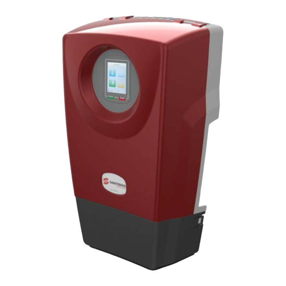
SUNWAY M XS
2200TL – 3000TL – 3800TL
SINGLE-PHASE SOLAR INVERTER
USER MANUAL
-Installation and Programming Instructions-
Elettronica Santerno S.p.A.
Strada Statale Selice, 47 - 40026 Imola (BO) Italy
Tel. +39 0542 489711 - Fax +39 0542 489722
santerno.com
sales@santerno.com
Advertisement
Table of Contents

Related Manuals for Santerno SUNWAY M XS


Summary of Contents for Santerno SUNWAY M XS
- Page 1 • Elettronica Santerno reserves the right to make any technical changes to this manual and to the device without prior notice. If printing errors or similar are detected, the corrections will be included in the new releases of the manual.
- Page 2 SUNWAY M XS 2200 TL 3000 TL 3800 TL...
-
Page 3: Table Of Contents
INSTALLATION AND SUNWAY M XS 3000TL PROGRAMMING INSTRUCTIONS 0. TABLE OF CONTENTS 0. TABLE OF CONTENTS.................... 3 0.1. INDEX OF FIGURES ....................5 0.2. INDEX OF TABLES ....................7 1. SCOPE OF THIS MANUAL ..................8 2. GENERAL INFORMATION ..................8 2.1. - Page 4 INSTALLATION AND SUNWAY M XS 3000TL PROGRAMMING INSTRUCTIONS 4.1. NAVIGATING IN THE GRAPHIC INTERFACE ............56 4.1.1. NAVIGATION BAR ........................58 4.1.2. MENU AREA ..........................58 4.1.3. STATUS BAR AREA ....................... 58 4.2. DISPLAY WINDOWS AND DATA ENTER WINDOWS .......... 61 4.2.1.
-
Page 5: Index Of Figures
Figure 7: SUNWAY M XS box with packing elements ..................18 Figure 8: Minimum clearance (in mm) to respect for proper ventilation of the SUNWAY M XS ..... 21 Figure 9: Detail of the SUNWAY M XS bracket with the fixing screws ............21 Figure 10: The SUNWAY M XS in upright position .................. - Page 6 INSTALLATION AND SUNWAY M XS 3000TL PROGRAMMING INSTRUCTIONS Figure 60: Screen of the inverter Status menu ....................60 Figure 61: Example of a measure graph ......................61 Figure 62: Example of an alphanumeric keypad window ................62 Figure 63: Example of a list window ........................ 63 Figure 64: Example of a Run Command window ....................
-
Page 7: Index Of Tables
Table 23: Measures in the Alarm History and Event History ................99 Table 24: List of the SUNWAY M XS alarms....................100 Table 25: Status messages for the SUNWAY M XS inverters ..............112 Table 26: DB9 connector - RS485 serial port ....................116 Table 27: Specifications of the RS485 serial port .................. -
Page 8: Scope Of This Manual
2.1. Description of the Product The inverters of the SUNWAY M XS series are full-digital devices that convert DC energy produced by photovoltaic (PV) panels – when radiated by sunlight – into AC energy, which is delivered to the grid. -
Page 9: Operating Principle
PV panels as well as the device controlling the operation in parallel to the grid are integrated into the inverter. Therefore, no additional device external to the inverter is required. Not fitted in the Sunway MXS 2200 TL Figure 1: Block diagram of the SUNWAY M XS 2.4. Main Standard Integrated Functions This section contains a brief description of the equipment functions, to allow users who are not familiar with the operation of PV fields to better understand this manual. -
Page 10: Attached Documentation
2.5. Attached Documentation The SUNWAY M XS inverter is supplied complete with the following documents: • Multilingual “Quick Start Guide”, included as a hard copy and available for download from santerno.com;... -
Page 11: Basic Installation
The basic installation consists in connecting the basic elements for the system operation (grid and PV generator). Advanced configurations of the SUNWAY M XS inverter are covered in section 4. Fully read the basic installation instructions before carrying out the advanced configurations. - Page 12 INSTALLATION AND SUNWAY M XS 3000TL PROGRAMMING INSTRUCTIONS CONNECTION TO THE PV FIELD – When exposed to solar radiation, the photovoltaic panels produce DC voltage that is applied to the inverter. ELECTRIC SHOCK HAZARD – Do not touch the electric parts of the inverter and do not operate on the inverter when it is powered.
-
Page 13: Checking The Product On Delivery
If the delivery does not match your order, contact the supplier immediately. Figure 2: Packaging of the SUNWAY M XS If the equipment is to be stored before installation, make sure that the ambient conditions in the warehouse meet the necessary specifications (see section 3.4.1). -
Page 14: Dataplate
3.2.1. Dataplate The product is described and identified by two dataplates placed on its side, as shown in Figure 3. Figure 3: Dataplates of the SUNWAY M XS The dataplate measures 60mm x 30mm. The product code is made up of the following elements:... - Page 15 Purchase code of the product: ZZ01770 Fixed figures of the purchase code: ZZ01770 for the SUNWAY M XS series Size (two figures): 22 = 2200 (2200 W rated power for 230 V grid) 30 = 3000 (3000 W rated power for 230 V grid)
-
Page 16: Figure 4: Label Placed On The Metal Enclosure Of The Product
INSTALLATION AND SUNWAY M XS 3000TL PROGRAMMING INSTRUCTIONS Figure 4: Label placed on the metal enclosure of the product The basic configuration of the SUNWAY M XS inverter comprises the following: • N. 1 SUNWAY M XS inverter • N. 1 Wall-mounting bracket •... -
Page 17: Transport And Handling
Always use proper handling equipment. 1. Unpacking the product: • Cut with pincers the plastic straps that fix the package of the SUNWAY M XS to the pallet; • Cut with a cutter the adhesive tape closing the box. -
Page 18: Figure 6: Procedure For Removing The Sunway M Xs From Its Packing
SUNWAY M XS 3000TL PROGRAMMING INSTRUCTIONS 2. Remove the SUNWAY M XS from its packing by lifting it from its sides. To avoid damaging the packing, lift the product keeping it horizontal to the floor (see Figure 6). Figure 6: Procedure for removing the SUNWAY M XS from its packing 3. -
Page 19: Installation
Table 1: Environmental requirements * The external fans are IP54 rated. ** Beyond 45 °C, the SUNWAY M XS automatically decreases the output power in order to avoid overheating. See the product specifications. Environmental conditions significantly affect the life-expectancy of the CAUTION product. -
Page 20: Wall Mounting
3.4.2. Wall Mounting The SUNWAY M XS is provided with a bracket that can be used for wall mounting. The inverter is to be installed in upright position. Make sure that the wall can withstand the weight of the product. -
Page 21: Figure 8: Minimum Clearance (In Mm) To Respect For Proper Ventilation Of The Sunway M Xs
8. The clearance below allow easy mounting and proper ventilation. Figure 8: Minimum clearance (in mm) to respect for proper ventilation of the SUNWAY M XS 2. N. 3 wall plugs, 6 mm flared head are required to fasten the wall-mounting bracket (plugs are not supplied with the product because different wall materials require different types of fixing devices). -
Page 22: Figure 10: The Sunway M Xs In Upright Position
3. Place the inverter upright in contact with the wall in the proximity of the fixing point. The inverter is equipped with feet for upright installation. Figure 10: The SUNWAY M XS in upright position 4. Fasten the SUNWAY M XS to the bracket by lifting it from the two side handles. HANGING POINTS... -
Page 23: Electrical Connection
DANGER before loosening your grip on the product. 5. Make sure that the SUNWAY M XS is firmly fixed to the wall. Make sure that no tilting occurs. 3.4.3. Electrical Connection Remove the cable cover at the bottom of the inverter in order to gain access to the connectors. -
Page 24: Figure 13: Sunway M Xs Connectors
INSTALLATION AND SUNWAY M XS 3000TL PROGRAMMING INSTRUCTIONS Figure 13: SUNWAY M XS connectors DANGER Always connect the protective earthing (PE). Follow the sequence below to carry out the electrical connection of the SUNWAY M XS. CAUTION 1. Carry out the earth connection of the inverter. -
Page 25: Table 2: Dimensioning Of The Mccb And Cable Specifications
INSTALLATION AND SUNWAY M XS 3000TL PROGRAMMING INSTRUCTIONS 3.4.3.1. Connection to the Grid The electrical connection of the SUNWAY M XS must follow the steps given CAUTION in section 3.4.3. Always remove voltage before operating on the grid. The earth DANGER conductor must be connected first. -
Page 26: Figure 14: Fixed Element Of The Grid Connector
INSTALLATION AND SUNWAY M XS 3000TL PROGRAMMING INSTRUCTIONS The connector is composed of a fixed element (see figure below): Figure 14: Fixed element of the grid connector and of a floating element supplied with the product. The installer shall connect the AC cable to this section according to the instructions given on the connector itself. -
Page 27: Figure 16: Mounting The Floating Connector For The Connection To The Grid
Up to two strings may be connected in parallel to the SUNWAY M XS (size 2200 and 3800), with no need to install any additional component. The strings forming the PV field and that are connected to the same SUNWAY M XS must be dimensioned in order to get the same working voltage per string. - Page 28 INSTALLATION AND SUNWAY M XS 3000TL PROGRAMMING INSTRUCTIONS SUNWAY M XS Model 2200TL 3000TL 3800TL Number of PV fields that can be connected Number of strings per PV field that can be connected Make sure that the safety circuit breaker is open and the earth connector DANGER (PE) is properly earthed.
-
Page 29: Table 3: Specifications Of The Pv Field
INSTALLATION AND SUNWAY M XS 3000TL PROGRAMMING INSTRUCTIONS The voltage produced by the photovoltaic generator radiated by sunlight (even weak sunlight) can reach dangerous voltage. Cable stripping and wiring must be carried out with extreme care using proper DANGER tools. It is advisable to cover the photovoltaic panels with a sun shade. -
Page 30: Figure 17: Polarity For String Connection To The Main Pv Field And Dc-Side Disconnect Switch
INSTALLATION AND SUNWAY M XS 3000TL PROGRAMMING INSTRUCTIONS Do the following: Make sure that the inverter is uncoupled from the AC grid. If the DC disconnect switch (optional) is fitted, set it to OFF (see Figure 17). Check polarity and voltage of each string. - Page 31 INSTALLATION AND SUNWAY M XS 3000TL PROGRAMMING INSTRUCTIONS 3.4.3.3. Specifications of the Quick-coupling Connectors Supplied with the Product The product houses unipolar conductors with cross-section 4 to 6 mm and outer diameter from 6.3 to 7.8 mm. Follow the instructions below to assemble the flying connectors.
-
Page 32: Figure 18: Removing The Protective Film From The Touchscreen Display
3.4.3.4. Removing the Protective Film from the Display The SUNWAY M XS inverter is supplied with a film protecting the touchscreen display. See Figure 18. Once the inverter installation is complete, remove the protective film from the touchscreen display to start using it. -
Page 33: Figure 19: Slots For The Application Of The Fiscal Seal
INSTALLATION AND SUNWAY M XS 3000TL PROGRAMMING INSTRUCTIONS 3.4.3.5. Fiscal Seal A fiscal seal may be applied to the inverter, where required. The seal may be applied through the special slots on both sides of the product cover and enclosure. Remove the connector protective cover to gain access to the slots. -
Page 34: Commissioning
4.1.3. The action of pressing the START button is permanently stored; therefore, if voltage is removed from the SUNWAY M XS, its Run status will still be NOTE active at next power on. The inverter must be restarted only after resetting an alarm or after pressing the STOP button. -
Page 35: Stopping The Inverter
12 hours after the commissioning of the inverter. Once started, the SUNWAY M XS operates in full automatic mode. The inverter operating conditions may be constantly monitored via the touchscreen display (see section 4). If not used for 5 minutes, the touchscreen display automatically turns off to minimize self-consumption. -
Page 36: Quick Configuration
INSTALLATION AND SUNWAY M XS 3000TL PROGRAMMING INSTRUCTIONS 3.6. Quick Configuration The Quick Configuration in the Tools menu guides the user through preset operations for a quick configuration of the product. The Quick Configuration comprises: 1. Setting the language. See section 3.6.1 2. -
Page 37: Setting The Country
After this time interval, the Country setting may be changed only by the Customer Service of Elettronica Santerno SpA. This section describes how to change the Country where the inverter is to be installed. Do the following: −... -
Page 38: Setting The Time Zone
INSTALLATION AND SUNWAY M XS 3000TL PROGRAMMING INSTRUCTIONS In summary: → → → → → Select the Tools Select the Quick Select P040 - Select a value Confirm with OK icon Configuration Country and press Save submenu Figure 24: Setting the Country During the time interval when the Country may be changed (12h), the start menu shows the name of the Country which is currently selected. -
Page 39: Setting The Date And Time
INSTALLATION AND SUNWAY M XS 3000TL PROGRAMMING INSTRUCTIONS Figure 26: Time zone setting page − Select the desired time zone; − Activate your choice by pressing the Save ( ) button and confirm with . The system automatically quits the current page. If you press Cancel ( ), the previous settings are maintained. -
Page 40: Figure 28: Setting The Date
INSTALLATION AND SUNWAY M XS 3000TL PROGRAMMING INSTRUCTIONS − Figure 28: Setting the date − Enter the date by pressing the buttons; − Activate your choice by pressing the Save ( ) button and confirm with . The system automatically quits the current page. If you press Cancel ( ), the previous settings are maintained;... -
Page 41: Setting The Currency
INSTALLATION AND SUNWAY M XS 3000TL PROGRAMMING INSTRUCTIONS 3.6.5. Setting the Currency This section describes how to change the currency. Do the following: − From the start menu, select the Tools ( ) icon; − Select the Quick Configuration ( ) menu. -
Page 42: Setting The Feed-In Tariff
INSTALLATION AND SUNWAY M XS 3000TL PROGRAMMING INSTRUCTIONS 3.6.6. Setting the Feed-in Tariff This section describes how to change the parameters of the inverter net metering. The net-metering function constantly informs the consumers about the economic return of their PV plant. You have to set up the remuneration of the generated energy acknowledged by your Grid Administrator. -
Page 43: Resetting The History Data
INSTALLATION AND SUNWAY M XS 3000TL PROGRAMMING INSTRUCTIONS 3.6.7. Resetting the History Data The Reset command resets the logs of the display history data and restarts the datalogging function for the integrity of the history data after the date and time have been changed. -
Page 44: Resetting The Display
INSTALLATION AND SUNWAY M XS 3000TL PROGRAMMING INSTRUCTIONS 3.6.8. Resetting the Display Resetting the display is required to ensure its correct operation after changing the display settings during the Quick Configuration procedure. Do the following: − From the start menu, select the Tools ( ) icon;... -
Page 45: Connectivity
The Wi-Fi transmitter is to be inserted into the USB connector using the special adapter. Figure 38: Inserting the Wi-Fi transmitter 3.7.1. Wi-Fi Connectivity The SUNWAY M XS features Wi-Fi 802.11 b/g connectivity for ad hoc (point-to-point) connection or for the connection of the inverter to a WLAN (wireless area network). NOTE The Wi-Fi connection is to be disabled before changing the Wi-Fi settings. -
Page 46: Figure 40: Setting The Ad Hoc Connectivity
INSTALLATION AND SUNWAY M XS 3000TL PROGRAMMING INSTRUCTIONS 3.7.1.2. AD HOC Connection The AD HOC connection enables connecting a PC to a different device allowing using one of the consulting methods in section 4 for one or more inverters, with no need to exploit an existing wireless network. -
Page 47: Figure 41: Setting The Router Connectivity
SUNWAY M XS 3000TL PROGRAMMING INSTRUCTIONS 3.7.1.3. Router Connection The SUNWAY M XS inverter may be connected only to WPA encrypted CAUTION networks by entering an alphanumeric password from 8 to 63 characters. The ROUTER connection allows connecting the inverter to an existing wireless infrastructure, thus allowing the other devices connected to the same network to use the consult methods in section 4 and allowing the inverter itself to gain access to the Internet in the event of an infrastructure connected to the network. -
Page 48: Figure 44: Ip Address Assignment Mode
INSTALLATION AND SUNWAY M XS 3000TL PROGRAMMING INSTRUCTIONS − Set the IP address assignment mode. Select: • “DHCP” if you desire that the IP address is assigned by the router or access point (factory setting). By selecting the “DHCP” mode, the additional connection parameters will be set up directly by the router or access point. -
Page 49: Accessing The Inverter Data
Network Administrator. 3.7.2. Accessing the Inverter Data The SUNWAY M XS may be monitored in wireless mode directly by the user, who can check status information, such as operating measures, alarms tripped and events fired, with no need to implement demanding wiring solutions. - Page 50 NOTE The iPhone application is available for iPhone 3 and more recent models. The iPhone Application developed by Elettronica Santerno for the connection to the SUNWAY M XS inverters may be downloaded from Apple iTunes. The iPhone Application allows displaying the status info of the inverter as well as the main operating measures, both in local mode and in remote mode—after the first connection in local mode has been...
-
Page 51: Sunwayportal.it
Navigate through the contents made available from the application. 3.7.3. Sunwayportal.it The SUNWAY M XS inverters, if connected to the Internet via Wi-Fi, may send the main info about the inverter status and measures to the Sunwaportal.it service of Elettronica Santerno SpA. Information may be accessed in remote mode as well. -
Page 52: Technical Support
PROGRAMMING INSTRUCTIONS 3.7.4. Technical Support The SUNWAY M XS inverters, if connected to the Internet via Wi-Fi, may be remotely accessed by the Customer Service of Elettronica Santerno SpA. Assistance is given via an encrypted communication channel between the inverter and Elettronica Santerno SpA Customer Service, whose staff is allowed to access the measures and programming parameters of the inverter. -
Page 53: Connectivity Troubleshooting
INSTALLATION AND SUNWAY M XS 3000TL PROGRAMMING INSTRUCTIONS 3.7.5. Connectivity Troubleshooting The desired network is not listed among the available networks Possible cause: The router cannot be detected by the inverter because it is too far The router has a hidden wireless network... -
Page 54: Datalogging
PROGRAMMING INSTRUCTIONS 3.8. Datalogging The SUNWAY M XS inverters may store the measures listed in Table 4. The user may display the history measures over 4 time intervals: − the latest day, considered as the latest 24 hours, with a resolution of 1 data item/minute;... -
Page 55: Graphic Interface Module
In the absence of solar radiation, the inverter will automatically deactivate. When solar radiation is enough to start the inverter, the SUNWAY M XS will automatically restart and will resume energy generation. The inverter may be restarted at any time by pressing the WAKE UP button from the graphic interface module. -
Page 56: Navigating In The Graphic Interface
INSTALLATION AND SUNWAY M XS 3000TL PROGRAMMING INSTRUCTIONS When the inverter is started, the touchscreen display shows the following screens in sequence: → → → → Santerno Logo Sunway M screen Loading… screen Start menu Default screen (Graph as a... -
Page 57: Figure 57: Example Of A Screen
INSTALLATION AND SUNWAY M XS 3000TL PROGRAMMING INSTRUCTIONS The graphic layout of the application is divided into 3 main areas: Area Description The Navigation Bar is populated by different icons allowing the user Navigation bar to know the navigation position inside the menus. Icons are displayed based on the selected items in the menus. -
Page 58: Navigation Bar
INSTALLATION AND SUNWAY M XS 3000TL PROGRAMMING INSTRUCTIONS 4.1.1. Navigation Bar The Navigation Bar displays the icons for easy navigation to the different menus and submenus: • Back to the start menu icon: allows going back to the start menu from any position in the menus. -
Page 59: Figure 59: Screen Of The Wi-Fi Status Menu
The icon can have four statuses: Hardware not fitted or hardware fault. If your SUNWAY M XS is provided with an external Wi-Fi connector, make sure that it is correctly inserted into the USB port of the inverter. If the Wi-Fi functionality is integrated into the product, the grey Wi-Fi icon may indicate that the Wi-Fi connection has been inactive for a while. -
Page 60: Figure 60: Screen Of The Inverter Status Menu
INSTALLATION AND SUNWAY M XS 3000TL PROGRAMMING INSTRUCTIONS • Inverter Status icon: allows accessing the inverter Status menu 4.3.9. Figure 60: Screen of the inverter Status menu The Status menu icon represents the operating conditions of the inverter. The icon can have three statuses: Indicates that the inverter is powered, but the PV field voltage is lower than the value set in parameter P020. -
Page 61: Display Windows And Data Enter Windows
INSTALLATION AND SUNWAY M XS 3000TL PROGRAMMING INSTRUCTIONS 4.2. Display Windows and Data Enter Windows The windows listed below make it possible to display the measures made available from the inverter and to change the system settings: 1. Graph window. See section 4.2.1. -
Page 62: Alphanumeric Keypad Window
INSTALLATION AND SUNWAY M XS 3000TL PROGRAMMING INSTRUCTIONS 4.2.2. Alphanumeric Keypad Window The alphanumeric keypad window enables entering alphanumeric values in the selected field, as detailed below: VALUE FIELD Displays the alphanumeric value relating to the selected parameter. MIN: Indicates minimum allowable value. -
Page 63: List Window
INSTALLATION AND SUNWAY M XS 3000TL PROGRAMMING INSTRUCTIONS 4.2.3. List Window The list window allows entering or changing a parameter chosen from a list, as detailed below: ITEM LIST Scrolling list of the available items. The currently active Arrow keys scrolling up and option is blue in colour. -
Page 64: Description Of The Menus
INSTALLATION AND SUNWAY M XS 3000TL PROGRAMMING INSTRUCTIONS 4.3. Description of the Menus The menus and submenus of the graphic interface module are divided into the four main areas represented by the four icons in the start menu. Figure 65: Icons of the Menu Area in the start menu 1. -
Page 65: Organisation Of Measures And Parameters
INSTALLATION AND SUNWAY M XS 3000TL PROGRAMMING INSTRUCTIONS 4.3.1. Organisation of Measures and Parameters The parameter configuration involves two access levels: • BASIC (factory setting): displays the main measures and parameters; • ADVANCED: displays the advanced measures and enables accessing all the parameters. -
Page 66: Table 5: Template Of The Measure Descriptive Tables
INSTALLATION AND SUNWAY M XS 3000TL PROGRAMMING INSTRUCTIONS The information and configuration variables are grouped as follows: Measures. These values may only be displayed and cannot be changed by the user. Each measure is identified by letter M followed by 3 digits (e.g. M001). Measures are detailed as follows in the... -
Page 67: Info Menu
INSTALLATION AND SUNWAY M XS 3000TL PROGRAMMING INSTRUCTIONS 4.3.2. Info Menu The icons of the menus and submenus in the Info area are blue in colour and allow monitoring the inverter measures. Each measure is identified by letter M followed by 3 digits. -
Page 68: Table 8: Info Menu, Field Submenu
INSTALLATION AND SUNWAY M XS 3000TL PROGRAMMING INSTRUCTIONS 4.3.2.1. Field Submenu Menu Submenu Access Level Action M000 – FIELD 1 VOLTAGE Displays the instant value of the PV field 1 BASIC Displays the measure graph. voltage NOTE: This measure is valid only if the PV field is coupled to the inverter M002 –... - Page 69 INSTALLATION AND SUNWAY M XS 3000TL PROGRAMMING INSTRUCTIONS M000 Range 0 ÷ 6200 0 ÷ 620.0 V Id/Address 1/1653 Field 1 Voltage Level BASIC Function PV field 1 voltage that has been measured. M001 Range 0 ÷ 6200 0 ÷ 620.0 V...
-
Page 70: Table 9: Info Menu, Inverter Submenu
• EVENT HISTORY History Displays the Event History. See section 4.3.6 for details. Select the icon to display the following items: • MLBL – SUNWAY M XS MODEL • PRSN – SERIAL NUMBER BASIC • L000 – DISPLAY SOFTWARE •... - Page 71 INSTALLATION AND SUNWAY M XS 3000TL PROGRAMMING INSTRUCTIONS M089 Range See Table 25 See Table 25 Id/Address 1/1662 Inverter Status Level BASIC Function Describes the operating conditions of the inverter. M090 Range See section 4.3.6 See section 4.3.6 Id/Address 1/7711...
-
Page 72: Table 10: Info Menu, Grid Submenu
INSTALLATION AND SUNWAY M XS 3000TL PROGRAMMING INSTRUCTIONS M058 Range -100 ÷ +120 -100.00 ÷ +150 °C Address 1/1660 Boost Level ADVANCED Temperature Function Measure of the heatsink temperature in the boost converter area. M059 Range -100 ÷ +120 -100.00 ÷ +120 °C... - Page 73 INSTALLATION AND SUNWAY M XS 3000TL PROGRAMMING INSTRUCTIONS M005 Range 0÷32768 0÷327.7Hz Id/Address 1/1658 Grid Frequency Level BASIC Function Measured grid frequency. 2200TL: 0 ÷ 1800 2200TL: 0 ÷ 18.0 A 3000TL: 0 ÷ 2400 3000TL: 0 ÷ 24.0 A...
-
Page 74: Graph Menu
INSTALLATION AND SUNWAY M XS 3000TL PROGRAMMING INSTRUCTIONS 4.3.3. Graph Menu The icon of the Graph menu is yellow in colour. The Graph menu displays a graph window (4.2.1) where up to three custom measures may be displayed. Measures may be selected from the Customization > Display >... -
Page 75: Figure 69: Steps To Take For The Customization Of The Measures To Be Graphically Displayed
INSTALLATION AND SUNWAY M XS 3000TL PROGRAMMING INSTRUCTIONS − Activate your choice by pressing the Save ( ) button and confirm with . The system automatically quits the current page. If you press Cancel ( ), the previous settings are maintained;... -
Page 76: Connectivity Menu
INSTALLATION AND SUNWAY M XS 3000TL PROGRAMMING INSTRUCTIONS − Activate your choice by pressing the Save ( ) button and confirm with . The system automatically quits the current page. If you press Cancel ( ), the previous settings are maintained;... -
Page 77: Table 11: Connectivity Menu, Wi-Fi Submenu
INSTALLATION AND SUNWAY M XS 3000TL PROGRAMMING INSTRUCTIONS 4.3.4.1. Wi-Fi Submenu Menu Submenu Access Level Action L399 – WI-FI STATUS Activates a list window. Select: − BASIC Displays current setting − parameter Activates a list window. Select: L305 – CONNECTION TYPE −... - Page 78 INSTALLATION AND SUNWAY M XS 3000TL PROGRAMMING INSTRUCTIONS L306 Range Alphanumeric value ranging from 8 to 63 characters Default Default Level BASIC Wi-Fi Password This variable contains the password enabling accessing the target Function wireless network for the Wi-Fi connection.
-
Page 79: Table 12: Connectivity Menu, Services Submenu
INSTALLATION AND SUNWAY M XS 3000TL PROGRAMMING INSTRUCTIONS 4.3.4.2. Services Submenu Menu Submenu Access Level Action Activates a list window. Select: L505 – SUNWAYPORTAL.IT − DISABLED BASIC Displays the current setting of the − ENABLED parameter Activates a list window. Select: L502 –... -
Page 80: Tools Menu
P, C, I, L and R followed by three digits. The SUNWAY M XS inverter is factory-set with a set of parameters fitting most applications. Therefore, the Quick Configuration settings are normally sufficient for the correct operation of the inverter. -
Page 81: Table 13: Tools Menu, Quick Configuration Submenu
INSTALLATION AND SUNWAY M XS 3000TL PROGRAMMING INSTRUCTIONS 4.3.5.1. Quick Configuration Submenu The Quick Configuration submenu groups the settings to be configured when commissioning the inverter for its correct operation. See section 3.6 for details. Menu Access Submenu Action Level Activates a list window. - Page 82 INSTALLATION AND SUNWAY M XS 3000TL PROGRAMMING INSTRUCTIONS L011 Range Default Display Reset Level BASIC Function This is a command to reset the touchscreen display. L400 Range 01/01/1970 ÷ 19/01/2038 Default 01/01/1970 Level BASIC Date Sets the date for the inverter. If the inverter is connected to the Internet, Function the date will be automatically updated.
-
Page 83: Figure 74: Tools Menu, Customization Submenu
INSTALLATION AND SUNWAY M XS 3000TL PROGRAMMING INSTRUCTIONS P130 Range 0 ÷ 10000 0.0 ÷ 10.000 Unit / kWh Default 0 Unit / kWh Level BASIC Incentive Address This parameter sets the remuneration per kWh produced. The currency Function may be set via parameter L403. - Page 84 INSTALLATION AND SUNWAY M XS 3000TL PROGRAMMING INSTRUCTIONS L451 Range See Table 4 Default MPWR Measure 1 Level BASIC Function Enables the customization of measure 1 in the main Graph. L452 Range See Table 4 Default EMPTY Measure 2 Level...
-
Page 85: Figure 75: Tools Menu, Advanced Configuration Submenu
ADVANCED Activates an alphanumeric keypad window. SW0 – SERVICE PASSWORD ADVANCED Enter the Service password. This functionality is reserved to the Customer Service of Elettronica Santerno SpA. Table 16: Tools menu, Customization submenu > Access Level 0: BASIC P001 Range 0 ÷... - Page 86 INSTALLATION AND SUNWAY M XS 3000TL PROGRAMMING INSTRUCTIONS Menu Access Submenu Action Level Activates a list window. Select one of the following: − P026 – MPPT 1 ADVANCED INACTIVE − ACTIVE Activates an alphanumeric keypad window. P020 – FIELD 1 REFERENCE ADVANCED Enter the desired value.
- Page 87 INSTALLATION AND SUNWAY M XS 3000TL PROGRAMMING INSTRUCTIONS P220 Range 1100÷4000 110.V÷400V Default 2800 280V Level ADVANCED Id/Address 1/255 Field 2 Reference If the MPPT algorithm is disabled for PV Field 2 (P226=Inactive), P220 Function represents the working voltage reference of PV Field 2: the inverter will try to make the PV field voltage match with the value set in P220.
- Page 88 INSTALLATION AND SUNWAY M XS 3000TL PROGRAMMING INSTRUCTIONS Grid interface See Table 19 Energy See Table 20 Figure 77: Tools menu, Advanced Settings > Grid submenu Menu GRID INTERFACE Access Submenu Action Level C000 – RATED GRID VOLTAGE Activates an alphanumeric keypad window.
- Page 89 INSTALLATION AND SUNWAY M XS 3000TL PROGRAMMING INSTRUCTIONS P092 – INSTANT GRID UNDERVOLTAGE Activates an alphanumeric keypad window. THRESHOLD ADVANCED Enter the desired value. Displays the value currently set for the parameter P093 – INSTANT UNDERVOLTAGE RELEASE Activates an alphanumeric keypad window.
- Page 90 INSTALLATION AND SUNWAY M XS 3000TL PROGRAMMING INSTRUCTIONS C001 Range 470 ÷ 630 47.0 ÷ 63.0 Hz Default 50.0 50.0Hz Level ADVANCED Rated Grid Frequency Id/Address 1 e 2/1308 Function This parameter sets the rated value of the grid frequency.
- Page 91 INSTALLATION AND SUNWAY M XS 3000TL PROGRAMMING INSTRUCTIONS P086 Range 1 ÷ 10000 0.001÷ 10.000s 100 (Italy), 0.1s (Italy), Default 150 (Spain), 0.15s (Spain), 200 (Germany) 0.2s (Germany) Maximum Level ADVANCED Voltage Trip Time Id/Address 1/1317 This is the time during which the maximum voltage trip condition must be Function maintained to prompt the activation of the grid maximum voltage fault.
- Page 92 INSTALLATION AND SUNWAY M XS 3000TL PROGRAMMING INSTRUCTIONS P092 Range 30 ÷ 95 [35 ÷ 95] % of Vn Default Level ADVANCED Instant Grid Undervoltage Id/Address 1/1323 Threshold This parameter, expressed as a percentage of the grid rated voltage, Function sets the activation threshold of the instant grid undervoltage fault.
- Page 93 INSTALLATION AND SUNWAY M XS 3000TL PROGRAMMING INSTRUCTIONS P098 Range 1 ÷ 10000 0.001 ÷ 10.000 s 50 (Italy), 0.05s (Italy), Default 50 (Spain), 0.05s (Spain), 200 (Germany) 0.20s (Germany) Maximum Level ADVANCED Frequency Trip Time Id/Address 1/1329 Time during which the trip condition of the maximum frequency must be Function maintained to prompt the activation of the grid maximum frequency fault.
- Page 94 INSTALLATION AND SUNWAY M XS 3000TL PROGRAMMING INSTRUCTIONS P103 Range 40 ÷ 10000 0.04 ÷ 10.0 s 100 (Italy), 0.10s (Italy), Default 100 (Spain), 0.10s (Spain), 10000 (Germany) 10.0s (Germany) Minimum Level ADVANCED Frequency Reset Time Id/Address 1/1334 Time during which the reset condition of the minimum frequency must be Function maintained to reset the minimum frequency fault.
-
Page 95: Table 21: Tools Menu, Commands Submenu
INSTALLATION AND SUNWAY M XS 3000TL PROGRAMMING INSTRUCTIONS 4.3.5.4. Commands Submenu Menu Access Submenu Action Level Displays the following: − I030 – TEST VMIN − I031 – TEST VMAX − I032 – TEST FMIN − AUTOTEST BASIC I033 – TEST FMAX Each item activates a run command window. - Page 96 INSTALLATION AND SUNWAY M XS 3000TL PROGRAMMING INSTRUCTIONS 0: Inactive I002 Range 0 ÷ 1 1: Active Default 0: Inactive Level ADVANCED Partial Energy Reset Id/Address 2/1389 Function Resets the partial active energy meter (M011). L011 Range Default Display Reset...
- Page 97 555: Active Default 0: Inactive Level BASIC Reset warning Id/Address 1 and 2/1400 Function Inactive functionality 4.3.5.5. Service Submenu The Advanced Configuration > Service submenu in the Tools menu comprises parameters reserved to the Customer Service of Elettronica Santerno SpA. 97/124...
-
Page 98: Alarms Menu
INSTALLATION AND SUNWAY M XS 3000TL PROGRAMMING INSTRUCTIONS 4.3.6. Alarms Menu When a safety device or an alarm trips, the inverter STOPS; the connection to the electric grid of the output power and the current delivery are inhibited. When an alarm message is displayed, find the cause responsible for the alarm before restarting the equipment. -
Page 99: Table 22: Alarms Menu
INSTALLATION AND SUNWAY M XS 3000TL PROGRAMMING INSTRUCTIONS Menu Access Submenu Action Level M089 – INVERTER STATUS BASIC Displays detailed information. Displays the current inverter status M090 – ACTIVE ALARM Displays detailed information. BASIC Displays the active alarm (if tripped) See section Table 24 or information on the displayed values. -
Page 100: Table 24: List Of The Sunway M Xs Alarms
2 are over 100. The SUNWAY M XS alarms are listed in Table 24. The alarm codes in the table are displayed by M090 in the Alarms menu and may be stored to the first item in every record of the Alarm History. - Page 101 Control board failure. Possible Causes NOTE: This alarm is displayed on the alarm history only. Solutions Contact the Customer Service of Elettronica Santerno SpA. A004-A104 Description Control board failure: Sect.A/Sect.B watchdog fault The autodiagnostics function of the control board constantly checks...
- Page 102 INSTALLATION AND SUNWAY M XS 3000TL PROGRAMMING INSTRUCTIONS A007-A107 Description Control board failure: Sect.A/Sect.B slow cycle overtime The autodiagnostics function of the control board constantly checks the correct operation of the programme installed on the Event microprocessors: a failure in the slow cycle programme has been detected.
- Page 103 INSTALLATION AND SUNWAY M XS 3000TL PROGRAMMING INSTRUCTIONS A013-A113 Description Control board failure: Sect.A/Sect.B communications failure The autodiagnostics function of the control board constantly checks Event its correct operation: a failure in the communications circuits between section A and section B has been detected.
- Page 104 INSTALLATION AND SUNWAY M XS 3000TL PROGRAMMING INSTRUCTIONS A028 Description Control board failure: grid measurement circuit failure The autodiagnostics function of the control board constantly checks Event its correct operation: a failure in the communications circuits between section A and section B has been detected.
- Page 105 INSTALLATION AND SUNWAY M XS 3000TL PROGRAMMING INSTRUCTIONS A034 Description Control board failure: programme locked in “wait” status Event The programme controlling the inverter is locked in “wait” status. Possible Strong electromagnetic conducted disturbance or radiated disturbance. Causes Reset the alarm (see Figure 80).
- Page 106 DC Overvoltage detected by the system software The field voltage has exceeded the maximum allowable threshold Event (580 V) for the safe operation of the inverter. PV generator incompatible with the amplitude of the SUNWAY M XS input voltage. Possible Causes Failure of the DC-bus voltage measuring circuit.
- Page 107 INSTALLATION AND SUNWAY M XS 3000TL PROGRAMMING INSTRUCTIONS A065 Description AC section overtemperature The temperature in the DC/AC conversion section is higher than the Event maximum allowable temperature. The temperature in the place where the inverter is installed is too high.
- Page 108 INSTALLATION AND SUNWAY M XS 3000TL PROGRAMMING INSTRUCTIONS A068 Description Insulation fault of the PV field The circuit measuring the insulation between the PV field and the Event earth has detected an impedance value lower than the allowable value. Possible Insulation loss between the PV field and the earth.
- Page 109 INSTALLATION AND SUNWAY M XS 3000TL PROGRAMMING INSTRUCTIONS A136 Description Protection against leakage current instant variations Instant variations of the leakage current exceeding the maximum allowable variations. The leakage current variation has been at the maximum value of 30 mA for 300 ms.
-
Page 110: Figure 79: Alarm Reset Screen
INSTALLATION AND SUNWAY M XS 3000TL PROGRAMMING INSTRUCTIONS 4.3.6.2. What to Do When an Alarm trips Read and make a note of the data items displayed for the alarm tripped from the ALARM HISTORY. Those data items are very useful to identify the cause responsible for the alarm and to find possible solutions. -
Page 111: Status Menu
Figure 80: Resetting an alarm The SUNWAY M XS inverters implement the Autoreset function; this means that the inverter tries to automatically restart when an alarm trips. The factory setting is four restart attempts. If the alarm persists even after 4 restart attempts occurring during a time interval of 5 minutes, the inverter enters an emergency condition that requires being manually reset by the user. -
Page 112: Table 25: Status Messages For The Sunway M Xs Inverters
The inverter is shutting down after having detected a field voltage POWER OFF value lower than 125V for the time set in P041. Table 25: Status messages for the SUNWAY M XS inverters 4.3.7.2. Status Info The Status Info field lists important operating conditions for the inverter operation: •... -
Page 113: Warnings
INSTALLATION AND SUNWAY M XS 3000TL PROGRAMMING INSTRUCTIONS 4.3.8. Warnings Warnings are service messages addressed to the user and are displayed in the Status Info field in the inverter Status window. When a warning appears, the Status window will include the “Warning” wording followed by the active warnings. -
Page 114: Wi-Fi Status Menu
INSTALLATION AND SUNWAY M XS 3000TL PROGRAMMING INSTRUCTIONS Warning Message Causes of the Warning POSITIVE POLE INSULATION The insulation to earth of the positive pole of the PV field is too FAILURE weak (lower than 700 kΩ). NEGATIVE POLE INSULATION... - Page 115 Technical Support is active: This means that the inverter is correctly connected to the Technical Support service, once this has been activated from the Services submenu in the Connectivity menu. In that case, the Customer Service of Elettronica Santerno SpA may operate on the inverter in remote mode.
-
Page 116: Advanced Installation
Serial Communications 5.1.1. General The SUNWAY M XS 2200, 3000 and 3800 inverters may be connected to a PC via serial link. This allows reading and writing all the parameters normally managed through the touchscreen display as well as the acquisition of the data processed by the inverter. -
Page 117: Communications Protocol
INSTALLATION AND SUNWAY M XS 3000TL PROGRAMMING INSTRUCTIONS The metal case of the connector is connected to the inverter grounding. Connect the braid of the shielded duplex cable used for serial communications to the metal case of the female connector that is to be connected to the inverter. -
Page 118: Usb Connection
5.2. USB Connection The inverters of the SUNWAY M XS series are provided with a USB connector featuring IP67 degree of protection. The USB connector is utilized for the connection of an external Wi-Fi dongle or a USB memory stick for the inverter software update. -
Page 119: Table 29: Protection Trip Times
* In some cases, the National Grid Administrator may require to change the values in brackets. If this is the case, please contact the Customer Service of Elettronica Santerno SpA. Value set on the inverters delivered in Italy starting from 01/04/2012 and... -
Page 120: Maintenance
• if the test fails, the inverter does not stop. This means that the interface protection has tripped. Please contact the Customer Service of Elettronica Santerno SpA. Figure 85: Test page Press the arrow button on the bottom-right corner to quit the test mode, or press the desired icon from the navigation bar. -
Page 121: Removing The Inverter
INSTALLATION AND SUNWAY M XS 3000TL PROGRAMMING INSTRUCTIONS 5.5. Removing the Inverter Follow the sequence below to remove the inverter from its installation place: 1. Set the inverter to OFF to cease power delivery; make sure that the symbol appears on the status bar of the display. -
Page 122: Figure 88: Removing The Quick-Coupling Connectors
INSTALLATION AND SUNWAY M XS 3000TL PROGRAMMING INSTRUCTIONS Figure 88: Removing the quick-coupling connectors 7. Remove the serial link connector (if any) 8. Remove the inverter Figure 89: Removing the inverter 122/124... -
Page 123: Specifications
Storage temperature (°C) -25 ÷ +70 Maximum relative humidity (%) Table 31: Specifications of the SUNWAY M XS inverters Weights and measures may vary based on the options required. The actual value depends on the real operating conditions of the grid. - Page 124 SUNWAY M XS 3000TL PROGRAMMING INSTRUCTIONS Power Limiting The Sunway M XS inverters may limit their output power based on 3 factors: Internal temperature The power limiting associated with the internal temperature decreases the power output by 20% every °C over 75 °C. This means that the output power is zero when the internal temperature reaches 80 °C.
Need help?
Do you have a question about the SUNWAY M XS and is the answer not in the manual?
Questions and answers