Table of Contents
Advertisement
Installation & Operations Manual
Element-P
With
SmartScan Maintenance Sensor
Patent Pending
"Please read this entire manual before installation and use of this pellet fuel-
burning room heater.
Failure to follow these instructions could result in
property damage, bodily injury or even death."
"Contact local building or fire officials about restrictions and installation
inspection requirements in your area.
Save these Instructions
1013
Element-P
1
Advertisement
Table of Contents

Related Manuals for St. Croix Element-P


Summary of Contents for St. Croix Element-P
- Page 1 Installation & Operations Manual Element-P With SmartScan Maintenance Sensor Patent Pending "Please read this entire manual before installation and use of this pellet fuel- burning room heater. Failure to follow these instructions could result in property damage, bodily injury or even death."...
-
Page 2: Table Of Contents
TABLE OF CONTENTS General Information ...................... 4 Installation Check List ....................5 Element-P Layout Diagram ..................6-7 Element-P Dimensions, Location & Clearances ............8 Approved Installations ....................8-9 Exhaust Venting......................10 Venting - Approved Materials ............... 10 Venting-Typical PL Vent Components............11 Venting - Determining Materials .............. - Page 3 Yearly Maintenance ....................43-45 Safe Operation ......................44 Wiring Schematic......................45 Troubleshooting & Frequently Asked Questions ..........46-50 Element-P Parts Breakdown ...................51-59 Warranty ........................60 Element-P Info & Notes....................61 Even Temp, Inc. P.O. Box 127 Waco, NE 68460 EMAIL: support@stcroixstoves.com WEB ADDRESS: www.stcroixstoves.com...
-
Page 4: General Information
Stove that is approved to burn wood pellets, Cherry Pits or a 50/50 percent Mixture of Wood pellets and Corn. This model is not intended as the sole source of heat. The Element-P is approved for the above mentioned fuels only. -
Page 5: Installation Check List
4. Caution: The high temperature paint can be easily scratched prior to burning the Multi-Fuel Stove. CAUTION FAILURE TO FOLLOW THE INSTRUCTIONS IN THE INSTALLATIONS MANUAL MAY RESULT IN A HOUSE FIRE. PLEASE FOLLOW INSTALLATION AND MAINTENANCE INSTRUCTIONS. TABLE OF CONTENTS Element-P... -
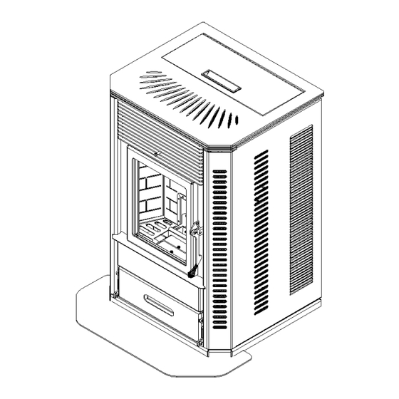
Page 6: Element-P Layout Diagram
Stove Layout Figure 1 There are two burn systems used in the Element-P. These systems are interchangeable in the stove body. This Manual covers the Element-P, which uses the Versa Grate System The “Versa Grate System”: A Fully Automatic System that offers Self-Ignition. This system is approved for Pellets &... - Page 7 Figure 2 Versa Grate System Approved with the Following Fuels: Pellets, Cherry Pits and a 50/50 percent Mixture of Pellets and Corn Element-P...
-
Page 8: Element-P Dimensions, Location & Clearances
H – Front of Stove to end of Exhaust Pipe Approved Installations The Element-P is approved for CONVENTIONAL and MOBILE HOME installations as a FREESTANDING stove. The stove may also be installed on the Hearth in front of a Fireplace and vented through the chimney of the fireplace. - Page 9 THE ELEMENT-P STOVE USES A POSITIVE PRESSURE VENT SYSTEM. DO NOT INSTALL A FLUE DAMPER IN THE EXHAUST SYSTEM OF UNIT DO NOT CONNECT THE ELEMENT-P STOVE TO A CHIMNEY SYSTEM THAT IS CONNECTED TO ANOTHER APPLIANCE. DO NOT INSTALL THIS UNIT IN A SLEEPING ROOM...
-
Page 10: Exhaust Venting
VENTING: APPROVED MATERIALS The Element-P requires a venting system approved for pellet or corn venting by a certified testing lab. Approved pellet or corn venting materials are: 1) PL vent, a double wall vent with a stainless steel liner; and 2) Single wall rigid or flexible stainless steel pipe. PL Vent and Single wall vent is available through manufacturers such as: ICC Pellet Vent, Energy Vent LTD, James A. -
Page 11: Venting-Typical Pl Vent Components
TYPICAL PL VENT COMPONENTS RAIN CAP VERTICAL OR WALL THIMBLE CHIMNEY SUPPORT BRACKET HORIZONTAL ADAPTER ADJUSTABLE LENGTH SINGLE TEE SINGLE REDUCTION DOUBLE TEE PIPE w/TEE CAP TEE w/TEE CAP w/TEE CAP PIPE ADAPTER INCREASER ELBOW ELBOW Element-P... -
Page 12: Venting: Determining Materials
FUEL REMAINS IN THE BURN GRATE. (See “Battery Backup” on page 9) 2. It is not recommended to run vertical venting outside the heated environment where the Element-P is installed. Running a venting system in a cold environment may cause the flue temperatures to cool down too much for adequate drafting. -
Page 13: Venting: Termination Requirements
4. Figure 4 4’ (1.2 m) BELOW a door, window, cavity, or air vent 4’ (1.2 m) HORIZONTALLY FROM a door, window, cavity, or air vent 1’ (305 mm) ABOVE a door, window, cavity, or air vent Element-P... - Page 14 9” from any opening through which vent gases could enter a building, and the vent terminal of such appliance with an input over 50000 BTU/Hr shall be located not less than 12” from the opening. Figure 5 9” (229 mm) ABOVE, BELOW OR HORIZONTALLY FROM a door, window, cavity, or air vent. Element-P...
-
Page 15: Venting: Termination Clearance Requirements
1’ (305 mm) FROM The wall penetration point 3’ (915mm) FROM a gas meter/regulator assembly 2’ (610 mm) FROM any adjacent combustibles such as: Adjacent buildings, fences, protruding parts of the structure, roof eaves or overhangs, plants, shrubs, etc. Element-P... -
Page 16: Venting: Into An Existing Chimney
3. Venting into the side of an existing masonry chimney must be done through a masonry thimble. When wall penetration is necessary to access a masonry chimney, use a listed PL vent wall thimble. (Figure 7). 4. When venting into a Class A steel chimney, use an appropriate PL Vent adapter. (Figure 8) Element-P... -
Page 17: Venting - Hearth Mount
(C). An approved flex liner or PL vent must be used. A chimney system with known drafting problems may require a liner, which may also need to be insulated to keep vent system warm in a cold chimney environment. Element-P... -
Page 18: Floor Protection
Unit and beyond each side of the Fuel Loading and Ash Removal Opening(s). Optional Spark Arrestor Pad provided with unit may only be used on a Solid Surface Floor, such as Wood Flooring, Laminate Flooring or Linoleum. Do not use on Carpet. Figure 10 Floor protection (Top View) Element-P... -
Page 19: Minimum Clearances
Floor protection: Front (from faceplate) 6” Floor protection: Sides & back of stove 0” Alcove: Vertical to Combustibles 16” Alcove: Sides 4” Alcove: Back 4” Figure 11 (Top View) Figure 12 (Top View) Clearances: corners of stove Clearances Sides and Back Element-P... - Page 20 Operations Manual. Please read the section covering Daily, Periodic Yearly Maintenance in the Operations Manual. Figure 15 Alcove Installation (Top View) Element-P...
-
Page 21: Combustion Air Requirements
COMBUSTION AIR 1. Under certain conditions it is recommended that the Element-P be connected to an outside source of combustion air to improve performance. Flexible metal hose, or rigid metal pipe, (conduit), must be connected around (NOT INSIDE) the combustion air inlet tube. -
Page 22: Mobile Home Installation
THE MOBILE HOME! FAILURE TO DO SO MAY CREATE NEGATIVE PRESSURE WITHIN THE MOBILE HOME AND COULD DISRUPT PROPER VENTING AND OPERATION OF THE PELLET STOVE. 3. CAUTION: THE STRUCTURAL INTEGRITY OF THE FLOORS, WALLS, CEILING AND ROOF MUST BE MAINTAINED. Element-P... -
Page 23: Use Of A Thermostat
The recommended heat settings while using a thermostat are any position between 2 through 5. Thermostat Hook-up Connect the wires from the thermostat to the external wire terminal on the back of the stove (see figure 18 on the following page). Element-P... - Page 24 Terminal on the back of the control board (See figure 19) Read Frequently Asked Questions section in the Operations Manual to Troubleshoot the Thermostat. Figure 19 NOTE: Installers must determine a neutral location of where to mount the thermostat for accurate room temperature measurements. Element-P...
-
Page 25: Element-P Operation
PREVENTING CHIMNEY FIRES Chimney fires can be prevented by properly operating the Element-P and by periodic inspection and cleaning of the chimney. When wood is burned it produces tar and other organic vapors, which combine with expelled moisture to form creosote. The creosote vapors condense in the relatively cool chimney flue associated with a slow burning fire. -
Page 26: Element-P Approved Fuels
CHERRY PITS - No Standard exists for Cherry Pits used as Fuel. Inspect fuel before buying. The Element-P was tested using Cherry Pits as a fuel by Intertek Testing Services; an independent Lab. Burning Cherry Pits requires the operator of the stove to monitor the fuel supply to make sure it is a viable product to use as a fuel. -
Page 27: Pre-Fire Instructions
9. Smoke detectors, installed in the same general area as the Element-P, may be activated if the Stove door is left open and smoke is allowed to enter the area. -
Page 28: Control Board Features
37 for more details running on. 1. The On/Off button not only turns the Element-P On and Off, it also resets the board if one of the sensors has detected a problem and the board is flashing a Diagnostic code. - Page 29 T-Stat Mode. The unit is hooked to a Thermostat and when calling for heat the Element-P will advance to the Heat level set at the Control board. Once the Heat demand has been met, the Stove will immediately shut down. Use this setting when heating a small area or when Temperatures are Moderate.
-
Page 30: Pre-Lighting & Lighting Instructions
DANGER - Risk of Fire or Explosion -Do not burn Garbage, Gasoline, Drain Oil or other Flammable Liquids. WARNING - The auger can start at any time while the Element-P is running REMEMBER: Read the manual before lighting the unit. - Page 31 Program 4 – LED lights flash four times Figure 21 Lighting Your Element-P with the Versa Grate System. (Program 3 & 4 only) 1. Make sure there are pellets in the hopper and the viewing door and ash pan door are closed.
-
Page 32: Shutting Off The Stove
1. Press the On/Off switch once; the lights will go off and the fire will go out in a few minutes. The board essentially goes into “Safety shutdown”. 2. As long as the temperature within the Element-P remains above 110°F both Fans will continue to run. When the P.O.F. switch drops out, the room fan shuts off and the Combustion fan will run for another 10 minutes and finally shut down completely. -
Page 33: Diagnostic & Safety Features
Check all Maintenance areas of the stove and the venting system for any conditions that can cause improper burning, such as, gaskets, door latch, ash pan latch, ash traps, ash clean out covers, plugged vent, plugged vent caps etc. Element-P... - Page 34 Normal Operating range. Shutting the unit down when fuel reaches this level, will trigger a diagnostic code that notifies the operator that the stove needs maintenance. The above list is intended as a guide to determine where the problem may Figure 22 Element-P...
- Page 35 “Power Reset” - If the board becomes unresponsive for a long period of time, you must unplug the Stove, wait 10 seconds and plug the unit back in to reset the board. WARNING: The Element-P has been Safety Tested by an accredited, independent laboratory. These safety features are designed to protect life and property. Bypassing these features voids all warranties and the safety listing of the Fairmont-P.
-
Page 36: Combustion Air Damper - Location And Adjustments
(Read “PREVENTING CHIMNEY FIRES” on Page 25) The damper on your Element-P has been limited at the factory using a setscrew. Do not move this screw. a. If a heavy black shiny build–up that is difficult to wipe off, is noticed on the glass and inner surfaces of the stove an adjustment decreasing the Combustion Air should be made. -
Page 37: Thermostat Control & Pilot Settings
The Element-P may be controlled with a thermostat to help maintain a more constant temperature. The Element-P may react a little slower to a thermostat compared to a Gas or Electric Stove. With this in mind the low setting can be adjusted to increase or decrease the amount of fuel used. -
Page 38: Element-P Maintenance
Element-P Maintenance NOTE: WHEN YOU FIRST OPERATE YOUR ELEMENT-P STOVE, CHECK TO DETERMINE THE FREQUENCY OF CLEANING. THE ELEMENT-P REQUIRES A MINIMUM AMOUNT OF DAILY MAINTENANCE. REQUIRED MAINTENANCE DEPENDS LARGELY UPON THE QUALITY OF FUEL BURNED AND THE RATE OF BURN. THE AMOUNT OF DAILY MAINTENANCE WILL INCREASE IF FUEL QUALITY DECREASES AND/OR THE BURNING RATE OF THE FUEL INCREASES. -
Page 39: Daily Maintenance (Versa Grate System)
Figure 24 Daily Maintenance – Element-P CAUTION: THE DOOR AND FRONT PART OF THE STOVE WILL BE HOT. DO NOT TOUCH ANY PART OF THE STOVE THAT IS HOT! CAUTION: NEVER ADD FIRE STARTER TO A HOT STOVE. 1. Check Grate Weldment and Shaker Plate (See figure 25) to determine if holes are plugged. -
Page 40: Periodic Maintenance
4. Once or twice daily pull the Heat Exchange Tube Scraper, (See Figure 25) out and back in to clean heat exchange tubes. Failure to operate the tube scraper daily may result Element-P... -
Page 41: Periodic Maintenance
3. Pull the Ash Shaker Rod (See figure 25) several times back and forth to shake the ashes down into the Ash Pan. 4. Clean-Out Ports. The Element-P Stove has 2 Exhaust Cleanout Ports located in the LEFT AND RIGHT lower corners of the firebox. Remove covers and clean regularly. - Page 42 Clean the baffle on a regular basis. Frequency of cleaning depends on amount of fuel being burnt and the quality of the fuel. Fuel with low ash content is recommended. Failure to clean the baffle can cause the Element-P Stove to become plugged with fly ash.
-
Page 43: Yearly Maintenance
Many dealers offer a Service Contract that will cover Yearly Maintenance. Contact your St. Croix Dealer for assistance in maintaining your Element-P in top condition. Yearly maintenance is designed to assure safe operation, prolong the life of the Element-P and help preserve its aesthetic appeal. -
Page 44: Safe Operation
Stove. If creosote has accumulated, it should be removed to reduce the risk of a chimney fire. 4. Do not Overfire this unit. Follow all instructions regarding the proper use of this heater. Element-P... -
Page 45: Wiring Schematic
Wiring Schematic Figure 28 The Electrical Rating of this Element-P Stove is: 120 Volt, 60 Hz, 4 Amp with the igniter running and approximately 2 Amp with out the igniter running. The minimum recommended circuit is 15 Amp. A dedicated circuit for the Stove is recommended. -
Page 46: Troubleshooting & Frequently Asked Questions
Stove fails to operate properly, troubleshooting by the operator of the Stove is limited. Please read the following guide for answers to frequently asked questions When first starting your Element-P the auger tube is empty and this will delay feeding fuel to the burn pot. This will in some cases prevent the Stove from starting. - Page 47 Use Caution when touching the sensor. It may knock the sensor out of alignment. When cleaning the sensor, never use alcohol or it will cloud the plastic lens. This will cause the sensor to fail over time. A soft dry cloth is best. Element-P...
- Page 48 Stove. It also could be an indication that the Stove is getting plugged and needs a good cleaning. Refer to the section in the manual that covers the Daily, Periodic and Yearly Maintenance of the Stove. Element-P...
- Page 49 There are 5 levels on the control board and they are indicated by single flash of the LED’s. The default setting is the bottom LED. This gives 5 adjustments increasing the voltage (LED’s 2 through 5) The voltage is increased or decreased 2.5 volts with each adjustment. Figure 31 Element-P...
- Page 50 12. Are there Cycle Time adjustments on the Control Board for different types of fuel? Answer: There are 4 individual programs on the control board; each has a different Cycle time. The Element-P only uses Program 3 and Program 4 Your Element-P has been factory set to Program 3.
-
Page 51: Element-P Parts Breakdown
PARTS LAYOUT Figure 34 Element-P... - Page 52 PARTS LAYOUT Figure 35 Element-P...
- Page 53 PARTS LAYOUT Figure 36 Element-P...
- Page 54 PARTS LAYOUT Figure 37 Figure 38 Element-P...
- Page 55 Sensor System Figure 39 Versa Grate Motor Assembly Figure 40 Figure 41 Element-P...
- Page 56 Figure 42 Element-P...
- Page 57 CONTROL BOARD BOX WITH CLINCH STUDS 80P30523B-R CONTROL BOARD 80P52658-R CONTROL BOARD HARNESS RESTRAINT NOT USED NOT USED 80P53681-R SLIDE-TOP STANDOFF PLATE ASSEMBLY 80P54176-R SHAFT CAGE WELDMENT 80P30045-R SPEAKER TERMINAL 80P52630-R TERMINAL BLOCK 80P52978-R VERSA GRATE SYSTEM ASSEMBLY 80P30809-R GLASS RETAINER Element-P...
- Page 58 8709K46 1/4" x 1" FOAM TAPE – 19.5” 80P20003-R CONVECTION FAN 80P20132-R DOOR GASKET – 48” 80P20131-R SMALL BRASS COIL 80P53773-R DOOR HANDLE - PAINTED 10-24X3-8BSHCS 10 - 24 X 3/8" BUTTON SOCKET CAP SCREW 80P53677-R MOUNT PLATE ASSEMBLY Element-P...
- Page 59 PART NUMBER DESCRIPTION 8X1/2HWHTEK-B #8 X 1/2" HWH TEK SCREW - BLACK 80P52947-R DOOR WELDMENT 80P52375-R DOOR GLASS 80P20022-R GLASS GASKET – 44” 80P52357-R GLASS RETAINER Element-P...
-
Page 60: Warranty
WARRANTY The Element-P, manufactured by Even Temp, Inc., is warranted for five (5) years, to the original owner, against defects and workmanship on all steel parts (excluding the burn grate) and two (2) year on electrical components from the date of sale to the original owner. There specifically is no warranty on the paint, glass, burn grate and all gaskets. -
Page 61: Element-P Info & Notes
Draft Trim: Circle one (See point 4 on page 29) LED #1 LED #2 LED #3 LED #4 LED #5 FUEL: Circle One PELLETS CORN WHEAT RYE CHERRY PITS DISTILLERS GRAIN PROGRAM: Circle one (see Figure 21 on page 31) Serial Number: Date of Purchase: Dealer Information: Element-P...
Need help?
Do you have a question about the Element-P and is the answer not in the manual?
Questions and answers