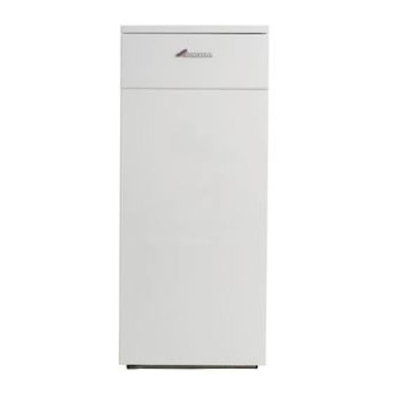
Summary of Contents for Worcester GREENSTAR UTILITY
- Page 10 Note: All dimensions are in metres unless stated otherwise. The maximum pipe run figures are based on using copper pipe with an inside diameter of 2mm less than the Ø. A top feed oil tank fitted with a de-aerator using an internal non-return valve should have any non- return valve/s fitted in the base of the tank to the suction line removed to assist purging air from the...
- Page 14 An air brick or other form of continuous air supply may have to be built into the installation in order to ensure an adequate supply of air. The minimum free area of each vent is shown opposite and depends whether the air is taken from another room or from outside the building.
- Page 15 There must be sufficient clearance around the appliance to allow proper circulation of ventilation air. The clearances required for installation and servicing will normally be adequate for ventilation.
- Page 16 See 'Contact Information' on the inside front cover Not applicable for flue guard information. N/A Not allowed CF Conventional flue RS(H) Room Sealed Horizontal flue RS(V) Room Sealed Vertical flue 1 An opening means an openable element, such as an openable window, or a permanent opening such as a permanently open air vent.
- Page 17 NOTE: The flue can be increased in size from the boiler take off point providing the joint is correctly sealed. Never reduce the flue diameter from the boiler take off point. Manufacturers of conventional flue systems suitable for this appliance are listed under 'Contact Information' on the inside front cover.
- Page 18 Effective length when engaged into sockets within the flue run is 950mm.
- Page 20 NOTE: For servicing purposes, keep the condensate and pressure relief discharge pipes away from components and pipework connections. NOTE: all horizontal flue sections must rise away from the boiler by 52mm per metre to ensure that condensate flows back into the boiler for safe discharge via the condensate waste pipe.
- Page 21 Note: to enable the panels to stand upright, reposition and secure the control box (G) to the side panels.
- Page 24 Note: that surplus water may be present due to factory testing.
- Page 25 The pump is factory set for single pipe operation with the flexible oil pipe fitted.
- Page 27 Route the power cable to the connection point avoiding any potentially hot surfaces with sufficient cable to move the control box into the service position. Open the control box into the service position to check the cable length and routing.
- Page 29 A frost thermostat can also be connected to the remote junction box if required.
- Page 32 Air will be automatically vented when the boiler is started up. The internal filter is accessed by removing the oil pump cover on the Danfoss BFP 11 L3 and Suntec AS47C.
- Page 33 If the burner fails to establish a normal firing pattern or flame failure occurs the flame monitoring photocell mounted in the burner body will alert the burner control box to shut the burner down and provide a safe lockout state indicated by the illumination of the lockout indicator (E).
- Page 34 The burner should be ON with the circulating pump. The burner and circulating pump should be off.
- Page 35 The inhibitor or combined inhibitor/anti-freeze must not cause damage to the materials within the boiler (mild steel, stainless steel, copper and brass) and any other materials/components within the system. NOTE: The concentration level of inhibitor in the system should be checked every 12 months or sooner if system content is lost.
- Page 36 Note: Release drain point (K) to drain the secondary heat exchanger.
- Page 37 To assist efficient boiler operation, the following should be carried out at least once a year. Operate the appliance and system and note any faults which may need to be corrected during the service. See the following instructions for detail of some of the service requirements listed below:...
- Page 44 Worcester, Bosch Group is a trading name of BBT Thermotechnology UK Ltd.
- Page 51 * If this clearance is less than 75mm the flue 'knock- out' panel sections must be removed to improve air circulation and cooling.
- Page 52 *Internal air to and from a space/room inside the building. **External air to and from directly outside the building.
- Page 53 (behind front top panel) (on burner control box, under top panel) (behind front panel) (behind front panel)
- Page 54 If the appliance is left unused and exposed to freezing conditions; shut off all the mains supplies, isolate the boiler and drain the system and boiler. The burner will run until the water reaches the set temperature on the heating control. Once the water temperature has been reached the burner turns off.
- Page 60 PROBLEM CAUSE REMEDY...
- Page 62 Worcester, Bosch Group is a trading name of BBT Thermotechnology UK Ltd.
-
Page 63: For Your Own Record
For your own record:... - Page 64 Worcester, Bosch Group is a trading name of BBT Thermotechnology UK Ltd.


Need help?
Do you have a question about the GREENSTAR UTILITY and is the answer not in the manual?
Questions and answers