
Summary of Contents for Blueview BV5000
- Page 1 BV5000 User Handbook Part Number: 202882-01 Revision: A Updated: April 2010 ©BlueView Technologies, Inc. All rights reserved. All product names are trademarks of their respective companies. www.blueview.com...
- Page 2 BlueView Technologies has made every effort to ensure the accuracy and completeness of this document; however, because ongoing development efforts are made to continually improve the capabilities of our products, we cannot guarantee the accuracy of the contents of this document. We disclaim liability for errors, omissions, or future changes herein.
-
Page 3: Table Of Contents
Connect Components ................12 Installing the Pan and Tilt Drivers ............. 13 Setup PC IP Address ................16 Connect to the BV5000................17 Installation of the Pan & Tilt Unit .............. 18 Chapter 4 ProScan Software Basics ........... 20 Typical ProScan Screenshot..............20 Image Display.................. - Page 4 Sonar + Pan & Tilt Connection Issues ............37 Pan & Tilt Connection Issues ..............37 Sonar Head Connection Issues ..............40 Image and Scan Problems ............... 43 BlueView Customer Support ..............45 Chapter 7 System Specifications..........46 Appendix A Typical Installation Configurations .....
-
Page 5: Chapter 1 Introduction
2D scanning sonar. This manual covers setup, installation, operation, and technical specifications of BlueView’s 3D mechanical scanning sonar system. When ordered, the BV5000 ships with either a 1.35 or 2.25 MHz sonar head, which are both covered in this manual. For specific details on individual sonar head specifications, see the specifications tables listed in the specification section of this manual. -
Page 6: System Overview
System Overview Through mechanical rotation of the sonar head, the BV5000 is capable of producing 3D point clouds from a stationary location. Some of the more common delivery methods (tripods and ROVs) are shown in the figures below. Notice the volumetric scan zones around the sonar. -
Page 7: Typical 3D Point Cloud Collection Overview
This section provides a quick overview of a typical collection process. Deploy the System Position the BV5000 into the desired scan location. For tripod type systems, verify that sonar is upright by viewing proper movement of the bottom imagery as the sonar is tilted up and down using the pan and tilt controls. -
Page 8: Chapter 2 Software Installation
“setup.exe” in the CD’s root directory. When ProScan starts, if a personal firewall is enabled, a warning message may pop up saying that ProScan is attempting to connect to the network. BlueView recommends selecting the option that will always allow ProScan to access the network (which it needs to do to communicate with sonar). -
Page 9: Leica Cyclone
Leica Cyclone Note: The Cyclone software package is sold separately from the base BV5000 package. Contact BlueView sales for more information on obtaining trial and permanent licenses for the Cyclone software package. Cyclone by Leica Geosystems is a point cloud manipulation software package... - Page 10 6. If the available licenses do not appear in the dialog, the individual licenses may need to be activated in the “License Manager” from the Help dropdown in the Navigator window. © BlueView Technologies Corp BlueView BV5000 User Handbook...
-
Page 11: Chapter 3 System Assembly And Testing
NOTE: Use the stickers, side indicators, and connector placement on the rear end cap of the sonar to determine the up-down orientation of the sonar. If the sonar is inverted be sure to select the “inverted” option in ProScan’s settings. © BlueView Technologies Corp BlueView BV5000 User Handbook... -
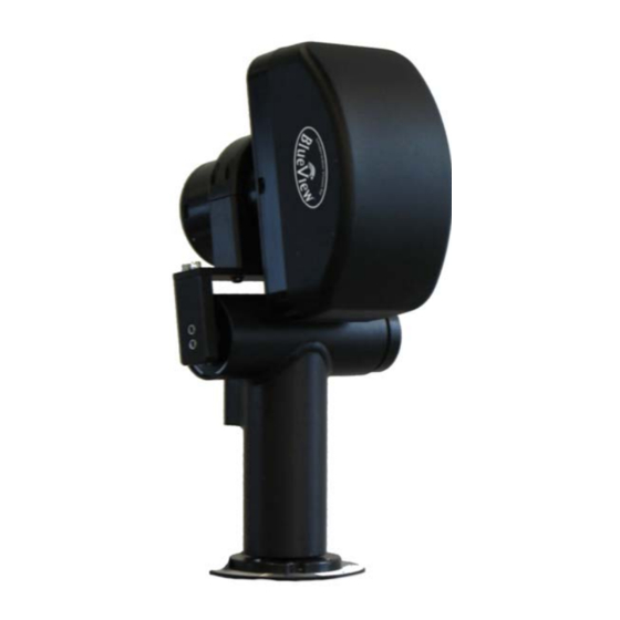
Page 12: Connect Components
Connect Components The BV5000 Package comes complete with everything needed to bench-test and tank test your system. 1. Connect the sonar and Pan & Tilt unit to the control box using the SPT (Sonar / Pan & Tilt) test cable. Connect the Ethernet cable to the control box, then to an available network connection port on the PC. -
Page 13: Installing The Pan And Tilt Drivers
The “Found New Hardware Wizard” will guide you through the installation process. 2. First, the USB Serial Converter driver will install. When prompted to use Windows Update to search for the driver select “No, not this time” and click “Next.” © BlueView Technologies Corp BlueView BV5000 User Handbook... - Page 14 “Search removable media (floppy, CD-ROM…)”. Then click on the “Next” button. 5. When the driver is successfully installed the following window will pop up. Click “Finish” to complete the installation of the first driver. © BlueView Technologies Corp BlueView BV5000 User Handbook...
- Page 15 Expand “Ports (COM and LPT)” and “Universal serial bus controllers”. A new “USB Serial Port” should appear in the “Ports” section and a “USB Serial Converter” should appear in the “Universal serial bus controllers” section. © BlueView Technologies Corp BlueView BV5000 User Handbook...
-
Page 16: Setup Pc Ip Address
Click the Networking tab. Under This connection uses the following items, click Internet Protocol Version 4 (TCP/IPv4), then click Properties. As described in the previous section, set the IP address to 192.168.1.3, and the subnet mask to 255.255.255.0. © BlueView Technologies Corp BlueView BV5000 User Handbook... -
Page 17: Connect To The Bv5000
Connect to the BV5000 After ProScan is installed and the PC configured, it’s time to connect to the system. Open the ProScan Software and click on the connect button, as shown below. Note: that if the sonar has just received power, it will take ~30 sec to boot and be ready for a connection. -
Page 18: Installation Of The Pan & Tilt Unit
2. Mount the base plate with the Socket Head Cap Screw on the OPPOSITE side of the connector when the Pan and Tilt is in the “Home” position. Use the Button Head Cap Screws at the other three locations. Socket Head Cap Screw Connector © BlueView Technologies Corp BlueView BV5000 User Handbook... - Page 19 +180 degrees in the Pan axis. The head of the sliding bolt should come in contact with the head of the Socket Head Cap Screw and slide in the slot. © BlueView Technologies Corp BlueView BV5000 User Handbook...
-
Page 20: Chapter 4 Proscan Software Basics
Chapter 4 ProScan Software Basics BlueView’s ProScan software is the main user interface for setting up and running a 3D scan operation. While ProScan can output 3D point cloud files in several formats, it does not work directly with 3D data sets. For viewing and manipulation of 3D data, see the following chapters regarding working with point clouds. -
Page 21: Image Display
File/Settings/Sonar Controls window. If no data in a given angle bin meets the threshold requirement, no blue is shown and no point is assigned in the point cloud for that angle. Copper Intensity Map Blue Range Data © BlueView Technologies Corp BlueView BV5000 User Handbook... - Page 22 Clockwise from upper left: Illustration of the multibeam collection, display of the line data in the copper color map, display of the blue threshold data points, display of the point cloud. © BlueView Technologies Corp BlueView BV5000 User Handbook...
-
Page 23: Toolbar
This allows the user to select a sonar file (.son) to open. Both playback and network output begin automatically. Network Transmit This function is not used with the BV5000 setup New File This function is not used with the BV5000 setup... -
Page 24: Range Controls
Range and Bearing The current range (meters) and bearing (degrees) of the cursor is displayed in the lower right corner of the ProScan window. © BlueView Technologies Corp BlueView BV5000 User Handbook... -
Page 25: Playback Controls
Function Icon Description Pause Pause playback at the current ping Play Resume playback Previous Ping Go to the previous ping Next Ping Go to the next ping © BlueView Technologies Corp BlueView BV5000 User Handbook... -
Page 26: Settings/Sonar Control
Settings/Sonar Control The only tabs of the Settings window you need to adjust when using the BV5000 are the Sonar Controls tab and the Scan Settings tab. The Settings window is accessible by clicking File Settings. The Scan Settings tab is discussed later in this manual. -
Page 27: Manual Image Calibration
If the diagonal line has a break in it, as shown in the left-hand figure below, bring up the Image Calibration dialog box, and move the slider until a single, unbroken line is displayed. Click OK to save the calibration value. © BlueView Technologies Corp BlueView BV5000 User Handbook... -
Page 28: Pan And Tilt Controls
Rotational scans are performed by clicking the Start Scan button on the Pan/Tilt control panel or by clicking File Start Scan. Both Single Scans and Spherical Scans can be performed from the Scan Setup window. © BlueView Technologies Corp BlueView BV5000 User Handbook... -
Page 29: Screen Information
Sound Speed This message displays the sound speed currently being used for image processing. This value is adjustable in the File/Settings/Sonar Controls window. © BlueView Technologies Corp BlueView BV5000 User Handbook... -
Page 30: Scan Setup
Spherical scans are created by taking several overlapping scans at different tilt angles. The Total Pan Angle and Center Scan option are applicable to spherical scans as well. © BlueView Technologies Corp BlueView BV5000 User Handbook... - Page 31 180, greater than 180), then the start and stop angles will be adjusted so that the total scan angle is still obtained. That is, if this option is checked when the current © BlueView Technologies Corp BlueView BV5000 User Handbook...
- Page 32 Scan Setup dialog box. This file name overrides the default name. Position and Orientation Input If the orientation and position of the BV5000 unit are known, that data can be entered in the Scan Setup dialog box. The exported point could files are adjusted such that the Z axis normal to the earth’s surface and the X axis is oriented north.
-
Page 33: Chapter 5 Recording And Reprocessing Data
Spherical Scan after they are merged as described later. If not checked, the individual files will be deleted after merging is complete. © BlueView Technologies Corp BlueView BV5000 User Handbook... -
Page 34: Scan Intensity Files (.Son)
Z values lower (deeper) than the sonar have negative values. If a depth value is provided as described in the Geo-referencing section below, then Z values deeper than the water surface have negative values, effectively moving the origin to the surface. © BlueView Technologies Corp BlueView BV5000 User Handbook... -
Page 35: Sonar Settings File (.Txt)
Reprocessing Saved Data As previously noted, one of the unique aspects of the BV5000 system is the ability to store raw scan data and reprocess this data at a later time. Some of the... - Page 36 Playback” button to start the reprocessing procedure. Once complete, ProScan creates new versions of the xyz and msh files. The raw .son file is left untouched. If MeshLab is installed, the new point cloud will be displayed as well. © BlueView Technologies Corp BlueView BV5000 User Handbook...
-
Page 37: Chapter 6 System Troubleshooting
System Troubleshooting This section is designed to help you quickly identify and solve issues dealing with the inability to connect the BlueView 3D scanning system from a PC. While the basic connections between the system and computer are straight forward, things can get very confusing once integrated into a delivery system. - Page 38 USB-to-RS485 converter is not functioning properly. If you were not able to connect to the pan and tilt, go on to the next section “Reinstall Drivers” © BlueView Technologies Corp BlueView BV5000 User Handbook...
- Page 39 The best way to verify proper voltage is by measuring the voltage at the sonar connector using a multimeter. Refer to the hardware manual using the detailed connector/pin information in Appendix A of the is manual © BlueView Technologies Corp BlueView BV5000 User Handbook...
-
Page 40: Sonar Head Connection Issues
If it doesn’t, click File -> Settings -> Sonar Connection to display the Sonar Connection Options. The sonar’s default network address is shown below. The Head Number for BlueView’s MicroBathymetry (MB series) sonar will be zero. The head number for non-MB sonar will be zero or one. - Page 41 Refer to the hardware manual for your specific sonar for detailed connector/pin information If you were not able to connect to the sonar, go on to the next section “Check Sonar” © BlueView Technologies Corp BlueView BV5000 User Handbook...
- Page 42 Use the following instructions to setup and test your sonar. Refer to section “Connect Components” in this manual for setup instructions. © BlueView Technologies Corp BlueView BV5000 User Handbook...
-
Page 43: Image And Scan Problems
Notepad. © BlueView Technologies Corp BlueView BV5000 User Handbook... - Page 44 A jagged step along vertical structures on overlapping scans would be visible in this case. To resolve the problem, readjust the sonar in its mount. © BlueView Technologies Corp BlueView BV5000 User Handbook...
-
Page 45: Blueview Customer Support
It is advised that you get your system integrator involved at this point. BlueView Technologies Customer Support www.blueview.com 206-545-7260 8am to 5pm PST Mon through Fri © BlueView Technologies Corp BlueView BV5000 User Handbook... -
Page 46: Chapter 7 System Specifications
None, 1 Stop Bit, No Flow None, 1 Stop Bit, No Flow Control Control File Output Types Data Output Formats .son, .off and .xyz files .son, .off and .xyz files Data Output Units meters meters © BlueView Technologies Corp BlueView BV5000 User Handbook... -
Page 47: Appendix A Typical Installation Configurations
Appendix A Typical Installation Configurations Typical Tripod and Fixed Configurations © BlueView Technologies Corp BlueView BV5000 User Handbook... -
Page 48: Typical Rov Configuration
Ethernet Orange Ethernet Rx- Ethernet Tx+ Ethernet Green/white Sonar Ethernet Tx- Ethernet Green Note: Try a straight Ethernet connection first. Then try a crossed connection (swap 1&3 , 2&6) Pan & Tilt © BlueView Technologies Corp BlueView BV5000 User Handbook... -
Page 49: Appendix B System And Cable Diagrams
8 Pin Connector to Sonar and Pan & Tilt Unit (Souriau UTG612-8PN) Function Ethernet RX+ (to sonar) Ethernet RX- (to sonar) Ethernet TX+ (to sonar) +24V DC 24 DC Common Ethernet TX- (to sonar) Data A (to P&T) Data B (to P&T) © BlueView Technologies Corp BlueView BV5000 User Handbook... -
Page 50: Pan And Tilt Outline Drawing
Pan and Tilt Outline Drawing Units: Inches © BlueView Technologies Corp BlueView BV5000 User Handbook... -
Page 51: Mb2250-45 Outline Drawing
MB2250-45 Outline Drawing Units: Inches © BlueView Technologies Corp BlueView BV5000 User Handbook... -
Page 52: Mb1350-45 Outline Drawing
MB1350-45 Outline Drawing Units: Inches © BlueView Technologies Corp BlueView BV5000 User Handbook...
Need help?
Do you have a question about the BV5000 and is the answer not in the manual?
Questions and answers