Samsung AQV09VBA Service Manual
Hide thumbs
Also See for AQV09VBA:
- Service manual (100 pages) ,
- User manual (30 pages) ,
- Service manual (67 pages)
Table of Contents
Advertisement
Quick Links
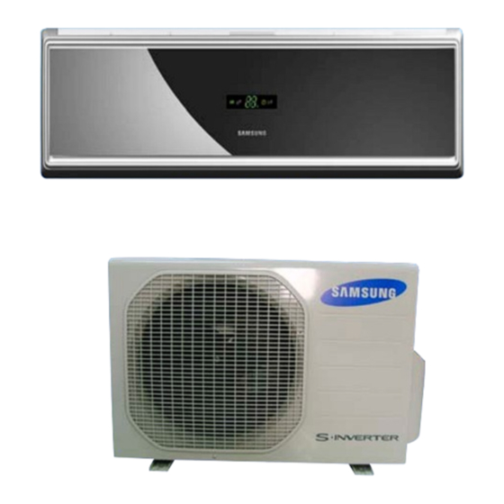
AIR CONDITIONER
AQV09VBCN, AQV12VBCN
AQV09VBCX, AQV12VBCX
Refer to the service manual in the GSPN(see the rear cover) for the more information.
SPLIT-TYPE AIR CONDITIONER
Basic : AQV09VBA
AQV12VBA
Model : AQV09VBC
AQV12VBC
Model Code : AQV09VBCN
AQV12VBCN
THE FEATURE OF PRODUCT
High Energy Efficiency BLDC
Air Conditioner
Luxury Half Mirror Design
Mode
:
Mode can help you sleep quickly and
soundly and wake up refreshed.
Mode
: The Micro Plasma Ion mode creates strong purified
zone in your room.
Silence Mode
: When you use the "Silence Mode", you can
experience extremely quiet operation of your
air conditioner.
AQV09VBCX
AQV12VBCX
Advertisement
Table of Contents

Subscribe to Our Youtube Channel
Related Manuals for Samsung AQV09VBA


Summary of Contents for Samsung AQV09VBA
-
Page 1: Air Conditioner
SPLIT-TYPE AIR CONDITIONER Basic : AQV09VBA AQV12VBA Model : AQV09VBC AQV12VBC Model Code : AQV09VBCN AQV09VBCX AQV12VBCN AQV12VBCX AIR CONDITIONER THE FEATURE OF PRODUCT High Energy Efficiency BLDC Air Conditioner Luxury Half Mirror Design Mode Mode can help you sleep quickly and soundly and wake up refreshed. -
Page 2: Table Of Contents
5-3 Ass’y Control In ..........................5-4 Ass’y Control Out ..........................16. Electrical Parts List ........................17. Wiring Diagram ..........................7-1 Indoor Unit ............................7-2 Outdoor Unit ............................ 18. Schematic Diagram ........................8-1 Indoor Unit ............................8-2 Outdoor Unit ............................ Samsung Electronics... - Page 3 14-2 Low Refrigerant Pressure Distribution 14-2 ..................14-3 Pressure & Capacity mark 14-3 ......................14-4 Q & A for Non-trouble 14-4 ........................14-5 Cleaning/Filter Change 14-7 ......................... 14-6 Installation 14-9 ............................14-7 Installation Diagram of Indoor Unit and Outdoor Unit 14-10 ............Samsung Electronics...
-
Page 4: Precautions
Do not place a cloth or other materials over it. Remove the batteries if you don’t use the remote control for a long time. (If applicable) Use the remote control within 7 meters from the indoor unit. (If applicable) Samsung Electronics... -
Page 5: Disposing Of The Unit
Young children or infirm persons should be always supervised when they use the air conditioner. Max current is measured according to IEC standard for safety. Current is measured according to ISO standard for energy efficiency. Samsung Electronics... -
Page 6: Product Specifications
Mode can help you sleep quickly and soundly and wake up refreshed. Mode The Micro Plasma Ion mode creates strong purified zone in your room. Silence Mode When you use the “Silence Mode”, you can experience extremely quiet operation of your air conditioner. Samsung Electronics... -
Page 7: Product Specifications
Outdoor Unit : DB7°C WB 6°C indoor 16°C ~ 32°C 16°C ~ 32°C cooling Outdoor -10°C ~ 43°C -10°C ~ 43°C Operation conditon range indoor -15°C ~ 30°C -15°C ~ 30°C heating Outdoor -15°C ~ 24°C -15°C ~ 24°C Samsung Electronics... -
Page 8: The Comparative Specifications Of Product
Noise Outdoor Unit 51dB 53dB Silver Nano Evaporator Silver Nano Evaporator Filter Anti-Allergy Filter Anti-Allergy Filter Air Purifying System Deodorizing Fiter Deodorizing Fiter Micro Plasma Ion MPI Mode MPI Mode Indoor Display Digital I Display Digital I Display Samsung Electronics... -
Page 9: Accessory And Option Specifications
Item Descriptions Code-No. Q'TY Remark Ass'y Plate Hanger DB97-02851B Remote Control DB93-04700P Batteries for Remote Control DB47-90024A Indoor Unit User’s Manual DB98-28491A Installation Manual DB98-28492A DB93-01549F 3-wire Power Cable (Europe) Drain Plug DB67-20011A Outdoor Unit Rubber Leg DB73-00182A Samsung Electronics... - Page 10 Product Specifications Accessories(cont.) Item Descriptions Code-No. Q'TY Remark 4-wire Assembly Cable DB39-01092B Assembly Pipe, ø6.35mm DB96-10453B Assembly Pipe, ø9.52mm DB96-10453F Accessory PE T3 Foam Tube Insulation DB72-50165A Vinyl Tape, Width 50mm DB72-00459A Drain Plug DB67-20011A Rubber Leg DB73-00182A Samsung Electronics...
- Page 11 Operating Instructions and Installation Accessories(cont.) Item Descriptions Code-No. Q'TY Remark Pipe Clamps A DB39-20224A Pipe Clamps B DB39-20224B Cement Nail Accessory M4x16 Tapping Screws 6002-000215 Drain Hose, length 2m DB62-00487A Putty 100g DB98-10568A Samsung Electronics...
-
Page 12: Alignment And Adjustments
• Because the Test Mode operate the cool mode by force not related to the set temperature / indoor temperature, check whether each subordinate is operated normally or not after completing installation and must turn off the power of the air conditioner. Samsung Electronics... -
Page 13: Indoor Display Error And Check Method
Indoor Fan Motor Abnormal Operation FAN Error Holding for 15 sec. at less than 450rpm 1min. Time out Communication MPI Error All Lamps Blink EEPROM Error All Lamps Blink Option Error Option Not Set up, Option Data Error Samsung Electronics... -
Page 14: Outdoor Led Error Display And Check Method
Fan error OTP error Compressor rotation error DC-Link voltage sensor error I_Trip error / PFC Over current GAS Leak error AC Line Zero Cross Signal out Power ON reset(1sec) Capacity miss match LED ON, LED OFF, LED BLINK Samsung Electronics... -
Page 15: Setting Option Setup Method
Setting is not required if you must Every time you push the button, the display panel reads a value which has a default. . . . repeatedly. Samsung Electronics... - Page 16 If all lamps of indoor unit are flickering, Plug out, plug in power plug again and press ON/OFF key to retry. If the unit is not working properly or all lamps are continuously flickering after setting the option code, see if the correct option code is set up for its model. Samsung Electronics...
-
Page 17: Option Items
Operating Instructions and Installation Alignment and Adjustments OPTION ITEMS REMOCON SEG1 SEG2 SEG3 SEG4 SEG5 SEG6 SEG7 SEG8 SEG9 SEG10 SEG11 SEG12 MODEL AQV09VBCN AQV12VBCN Samsung Electronics... -
Page 18: Disassembly And Reassembly
4. Disassembly and Reassembly Necessary Tools Item Remark +SCREW DRIVER MONKEY SPANNER Samsung Electronics... -
Page 19: Indoor Unit
2) Please open the front grille. 3) Please detach link grilles from main frame. 4) To detach front grille from main frame, please catches finger stop 5) Please loosen clamping screw and detach the terminal cover. 6) Please take out filter to downward. Samsung Electronics... - Page 20 2EA at the front of the panel front. 9) Loosen the screw of the ASSY DISPLAY. 10) Please separate Linked connector from the assy display. 11) Unlock 2 hooks between panel front and try drain to seperate panel front. Samsung Electronics...
- Page 21 12) Unlock 2 hooks between panel front and back body. TRAY DRAIN 1) Please detach stepping motor wire. 2) Please pull tray drain and separate from back body. evap 1) Loosen the ground wire screw. 2) Detach the temperature sensor. 3) Detach the holder pipe. Samsung Electronics...
-
Page 22: Outdoor Unit
5) Loosen 1EA screw, right of holder motor. 6) Detach the heat exchanger from indoor unit. MAIN PCB 1) Loosen 4EA screws of holder. 2) Detach Link wires of indoor, outdoor unit and fan motor. 3) Detach assy control from indoor unit. Samsung Electronics... - Page 23 Disassembly and Reassembly Parts Procedure Remark Fan Motor 1) Loosen 2EA screws of holder motor and & Detach the holder. Cross Fan 2) Loosen a screw and detach the cross fan. 3) Detach the holder bearing and motor. Samsung Electronics...
- Page 24 Cabinet Front lower to detach the Cabinet Front. (Use +Screw Driver.) 3) Detach the Cabinet Front like the picture on the right side. 4) Loosen 1 screw(CCW) fixed to assemble Plate Control Out with Cabinet-Side RH. (Use +Screw Driver.) Samsung Electronics...
- Page 25 5) Loosen 2 fixing screws(CCW) on the rear side of Cabinet-Side RH. (Use +Screw Driver.) 6) Loosen 3 screws(CCW) fixed to assemble Bracket Valve with Cabinet-Side RH. (Use +Screw Driver.) 7) Loosen 2 fixing screws(CCW) of Cabinet Side LF. (Use +Screw Driver.) Samsung Electronics...
- Page 26 1) Detach the Motor Wire from the PCB of Ass'y Control Out. 2) Detach several connectors from the PCB of Ass'y Control Out. 3) Detach 2 Connect Wires from Reactor. 4) Loosen 1 screw(CCW) fixed to assemble Ass'y Control Out with Partition. (Use +Screw Driver.) Samsung Electronics...
- Page 27 2) Detach the Terminal Cover and detach the Connect Comp Wire from Compressor. 3) Disassemble the Felt Comp Sound. 4) Loosen the 3 bolts(CCW) at the bottom of Compressor like the picture on the right side. (Use Monkey Spanner.) 4-10 Samsung Electronics...
- Page 28 MEMO Samsung Electronics 4-11...
-
Page 29: Exploded Views And Parts List
�� � �� �� � � � ��� � �� � ��� � ��� ��� ��� ��� ��� ��� ��� ��� ��� ��� ���� ���� ��� ���� ��� ���� ���� ���� ��� ��� ��� ���� ���� ���� ��� Samsung Electronics... - Page 30 Class E DB94-01152B ASSY BODY BACK ASS’Y 13-1 DB61-03028A BODY BACK HIPS 13-2 DB93-04230A ASSY COMPACT MPI ASS’Y 13-3 DB63-01583A COVER MPI HIPS DB61-01638B HOLDER PIPE HIPS DB67-00499C CAP SCREW HIPS DB70-00534A PLATE HANGER SGCC-M DB93-04700P ASSY REMOCON ARH-1346 Samsung Electronics...
-
Page 31: Outdoor Unit
�� �� �� �� �� �� �� �� �� �� �� �� � ���� �� ���� ���� � � ���� ���� � ���� ���� �� ���� ���� ���� ���� ���� �� � �� �� � � � � Samsung Electronics... - Page 32 ASS'Y CONTROL OUT ASS'Y DB93-05534F ASS'Y CONTROL OUT ASS'Y DB64-02028A SCREEN COND BAR P.E.H 100% DB32-00176D THERMISTOR OUT/DIS ASS’Y DB32-00121B THERMISTOR COND ASS’Y DB93-04489A CONNECT WIRE COMP ASS’Y DB63-01934A FELT COMP SIDE OUT ASS’Y DB63-02034A FELT COMP UPPER OUT ASS’Y Samsung Electronics...
-
Page 33: Ass'y Control In
DB95-01113A SENSOR 4P(103AT) DB91-00434A ASSY POWER CORE H05VV-F 3*1.0, Core DB93-04622A CONNECT WIRE DISPLAY DB93-04430A ASSY MODULE PCB MODULE DB93-04484A CONNECT WIRE STEP MOTOR, GRILL DB93-04367A CONNECT WIRE POWER DB93-04695A CONNECT WIRE MPI ASSY 6001-000725 SCREW-MACHINE TH M4*L16 Samsung Electronics... - Page 34 MEMO Samsung Electronics...
-
Page 35: Ass'y Control Out
5-4 Ass'y Control Out AQV09VBCX : DB93-05534E AQV12VBCX : DB93-05534F Samsung Electronics... - Page 36 SCREW-TAPPING PH+,M3,20 DB95-01140B TERMINAL BLOCK TERMINAL BLOCK-ASSY DB61-00250A HOLDER-WIRE CLAMP HOLDER-WIRE CLAMP 6002-000234 SCREW TH +,M4,L10 DB81-00547B INSULATOR-KFR MICA 6009-001001 SCREW TH+,M4,L8 DB65-10088D CABLE-TIE NYLON66 2301-001377 C-FILM,LEAD-OTHER 1.2uF,450V 6003-000336 SCREW TH,+,-,M4,L10,ZPC,SM20C,-,- 6002-000560 SCREW-TAPPING PH+,M4,2S,L10 6002-000630 SCREW PH +,2S,M3,L8 Samsung Electronics...
-
Page 37: Electrical Parts List
R-CHIP 1Kohm,5%,1/10W,TP,1608 R211 2007-000078 R-CHIP 1Kohm,5%,1/10W,TP,1608 R401 2007-000078 R-CHIP 1Kohm,5%,1/10W,TP,1608 R402 2007-000078 R-CHIP 1Kohm,5%,1/10W,TP,1608 R404 2007-000078 R-CHIP 1Kohm,5%,1/10W,TP,1608 R409 2007-000078 R-CHIP 1Kohm,5%,1/10W,TP,1608 R503 2007-000078 R-CHIP 1Kohm,5%,1/10W,TP,1608 R602 2007-000078 R-CHIP 1Kohm,5%,1/10W,TP,1608 R604 2007-000078 R-CHIP 1Kohm,5%,1/10W,TP,1608 R610 2007-000078 R-CHIP 1Kohm,5%,1/10W,TP,1608 Samsung Electronics... - Page 38 C-CER,CHIP 100nF,+80-20%,25V,Y5V,1608 C504 2203-000189 C-CER,CHIP 100nF,+80-20%,25V,Y5V,1608 C505 2203-000189 C-CER,CHIP 100nF,+80-20%,25V,Y5V,1608 C506 2203-000189 C-CER,CHIP 100nF,+80-20%,25V,Y5V,1608 C507 2203-000189 C-CER,CHIP 100nF,+80-20%,25V,Y5V,1608 C508 2203-000189 C-CER,CHIP 100nF,+80-20%,25V,Y5V,1608 C509 2203-000189 C-CER,CHIP 100nF,+80-20%,25V,Y5V,1608 C510 2203-000189 C-CER,CHIP 100nF,+80-20%,25V,Y5V,1608 C102 2203-000192 C-CER,CHIP 100nF,+80-20%,50V,Y5V,2012 C201 2203-000192 C-CER,CHIP 100nF,+80-20%,50V,Y5V,2012 Samsung Electronics...
- Page 39 VIVACE-PJT 9K/12K,CEM-3,2,1.0,T DB41-00526A PCB MAIN 1.6mm,160*140mm,-,2,-,- F701 DB61-00924A HOLDER-FUSE -,FH-51B,-,-,-,-,SSEC IC04 DB91-00376A ASSY-MICOM INV-Vivace1,MB90F823, 80P, ROM 128K bytes DB93-04814A ASSY CONNECTOR WIRE FORTE1-PJT,UL1015 20AWG CN63 3711-000999 HEADER-BOARD TO CABLE BOX,5P,2.5mm,STRAIGHT,WHT CN21 DB93-04256A ASSY PCB SUB ASSY PCB COMM AC Samsung Electronics...
- Page 40 47Kohm,5%,3W,AA,TP,6x16mm R702 2003-000855 R-METAL OXIDE(S) 47Kohm,5%,3W,AA,TP,6x16mm R703 2003-002007 R-METAL OXIDE(S) 4.7Kohm,5%,2W,AF,TP,3.9x10mm R704 2003-002007 R-METAL OXIDE(S) 4.7Kohm,5%,2W,AF,TP,3.9x10mm R706 2007-000282 R-CHIP 100Kohm,5%,1/8W,TP,2012 R707 2007-000468 R-CHIP 1Kohm,5%,1/8W,TP,2012 ZD71 0403-000537 DIODE-ZENER 1N4749A,5%,1000mW,DO-41,TP DB41-00527A PCB SUB FORTE,CEM-3,2,1.0,T1.6,50x33mm,-,9,-,COMM AC DB93-04350B ASS’Y CONNECTOR WIRE-PCB AQV12FA,12K_In Samsung Electronics...
- Page 41 R-METAL OXIDE(S) 47Kohm,5%,3W,AA,TP,6x16mm R418 2006-001013 R-CEMENT 0.02ohm,5%,7W,CA,BK,35x9.5x9.5mm R308 2007-000070 R-CHIP 0ohm,5%,1/10W,TP,1608 R419 2007-000074 R-CHIP 100ohm,5%,1/10W,TP,1608 R420 2007-000074 R-CHIP 100ohm,5%,1/10W,TP,1608 R421 2007-000074 R-CHIP 100ohm,5%,1/10W,TP,1608 R422 2007-000074 R-CHIP 100ohm,5%,1/10W,TP,1608 R423 2007-000074 R-CHIP 100ohm,5%,1/10W,TP,1608 R424 2007-000074 R-CHIP 100ohm,5%,1/10W,TP,1608 R425 2007-000074 R-CHIP 100ohm,5%,1/10W,TP,1608 Samsung Electronics...
- Page 42 R-CHIP 10Kohm,5%,1/8W,TP,2012 R116 2007-000385 R-CHIP 14.3Kohm,1%,1/4W,TP,3216 R539 2007-000493 R-CHIP 2.2Kohm,5%,1/8W,TP,2012 R540 2007-000493 R-CHIP 2.2Kohm,5%,1/8W,TP,2012 R541 2007-000493 R-CHIP 2.2Kohm,5%,1/8W,TP,2012 R453 2007-000516 R-CHIP 2.7Kohm,1%,1/10W,TP,1608 R807 2007-000553 R-CHIP 20ohm,5%,1/4W,TP,3216 R407 2007-000781 R-CHIP 33ohm,5%,1/8W,TP,2012 R408 2007-000781 R-CHIP 33ohm,5%,1/8W,TP,2012 R409 2007-000781 R-CHIP 33ohm,5%,1/8W,TP,2012 Samsung Electronics...
- Page 43 C-CERAMIC,DISC 2.2NF,10%,2KV,Y5P,TP,13X5MM,10 C901 2201-000322 C-CERAMIC,DISC 2.2NF,10%,2KV,Y5P,TP,13X5MM,10 C108 2203-000189 C-CER,CHIP 100nF,+80-20%,25V,Y5V,1608 C112 2203-000189 C-CER,CHIP 100nF,+80-20%,25V,Y5V,1608 C116 2203-000189 C-CER,CHIP 100nF,+80-20%,25V,Y5V,1608 C121 2203-000189 C-CER,CHIP 100nF,+80-20%,25V,Y5V,1608 C202 2203-000189 C-CER,CHIP 100nF,+80-20%,25V,Y5V,1608 C408 2203-000189 C-CER,CHIP 100nF,+80-20%,25V,Y5V,1608 C412 2203-000189 C-CER,CHIP 100nF,+80-20%,25V,Y5V,1608 C413 2203-000189 C-CER,CHIP 100nF,+80-20%,25V,Y5V,1608 Samsung Electronics...
- Page 44 4.7nF,10%,50V,X7R,1608 C906 2203-001562 C-CER,CHIP 10nF,+80-20%,50V,Y5V,2012 C907 2203-001562 C-CER,CHIP 10nF,+80-20%,50V,Y5V,2012 C451 2203-002002 C-CER,CHIP 33pF,5%,50V,NPO,BK,1608,- C402 2203-002041 C-CER,CHIP 0.47nF,10%,50V,X7R,1608 C404 2203-002041 C-CER,CHIP 0.47nF,10%,50V,X7R,1608 C406 2203-002041 C-CER,CHIP 0.47nF,10%,50V,X7R,1608 C407 2203-002041 C-CER,CHIP 0.47nF,10%,50V,X7R,1608 C113 2203-005819 C-CER,CHIP 1000nF,+80-20%,16V,Y5V,-,1608 C900 2203-006104 C-CER,CHIP 1000nF,10%,50V,X7R,3225 Samsung Electronics 6-10...
- Page 45 PCB MAIN FORTE,CEM-3,2,1.0,1.6t,160*140,-,1,-,- IC01 DB91-00381A ASSY-MICOM 2007 INV Comp Driver,MB90F823, 80P, ROM 128K bytes DB93-04336A ASSY CONNECTOR WIRE AQV12JAKCV,12K ASSY CONNECTOR DB93-04348B AQV12JAKCV,Out_12k WIRE-REACTOR ASSY CONNECTOR DB93-04348C AQV12FA,Out_12k WIRE-COMM AC ASSY CONNECTOR DB93-04349A AQV12JAKCV,12K_Out WIRE-4WAY DB95-00599A ASSY-IPM KFR-35GW/GPI,INVERTER 4-28 Samsung Electronics...
- Page 46 -,-,-,-,-,-,-,-,-,-,-,-,-,-,-,-,-,-,-,-,-,-,-,-,-,-,-,-,-,-,-,-,-,-,-,-,-,-,-,-, LED3 DB98-16602A ASSY-LED YEL -,-,-,-,-,-,-,-,-,-,-,-,-,-,-,-,-,-,-,-,-,-,-,-,-,-,-,-,-,-,-,-,-,-,-,-,-,-,-,-, PT02 DB98-20602A ASSY-PULSE TRANS KFR-35GW/GPI,INVERTER R106 DB98-20665A ASSY-RESISTOR KFR-35(25)GW/GPI,1.8k F 1608 IC81 DB98-20678A ASSY-PHOTOCOUPLER KFR-35(25)GW/GPI,TLP351 IC11 DB98-20679A ASSY-FPS KFR-35(25)GW/GPI,FSDH321 C101 DB98-21655A ASSY-CAP KFR-35(25)GW,KMH400VS470 C102 DB98-21655A ASSY-CAP KFR-35(25)GW,KMH400VS470 C103 DB98-21655A ASSY-CAP KFR-35(25)GW,KMH400VS470 Samsung Electronics 4-29...
- Page 47 1405-000154 VARISTOR 460Vdc,2500A,17.5x7.5mm,TP VA09 1405-000154 VARISTOR 460Vdc,2500A,17.5x7.5mm,TP 6042-001009 EYELET ID1.8,OD2.2,L3,-,BRASS DB39-00514F CBF LEAD WIRE-EARTH -,KFR-35(25)GW/GPI,-,200,-,-,-,GRN/YEL,-,-,- DB39-00961T CBF LEAD WIRE -,SH12BWH,-,120,10A,230V/50Hz,-,BRW,-,-,INVERTER DB39-00961U CBF LEAD WIRE -,SH12BWH,-,120,10A,230V/50Hz,-,BLU,-,-,INVERTER DB39-00998C CBF LEAD WIRE-POWER -,KFR-35(25)GW,2P,140,-,220V,-,BRN/SKYBLU,-,-, AC POWER WIRE DB41-00532A PCB SUB FORTE,FR-1,1,1.0,1.6T,160x140mm,-,3,-,- 6-11 Samsung Electronics...
-
Page 48: Wiring Diagram
7. Wiring Diagram 7-1 Indoor Unit This Document can not be used without Samsung’s authorization. Samsung Electronics... -
Page 49: Outdoor Unit
7-2 Outdoor Unit This Document can not be used without Samsung’s authorization. Samsung Electronics... - Page 50 MEMO Samsung Electronics...
-
Page 51: Schematic Diagram
8. Schematic Diagram 8-1 Indoor Unit This Document can not be used without Samsung’s authorization. Samsung Electronics... -
Page 52: Outdoor Unit
8-2 Outdoor Unit This Document can not be used without Samsung’s authorization. Samsung Electronics... -
Page 53: Circuit Descriptions
9-1-1 Indoor Unit SMPS PART BUZZER PART INDOOR FAN CONTROL SUB PCB CONNECTOR ZERO CROSSING PART DISPLAY PART INDOOR TEMPERATURE SENSOR STEP MOTOR & ION MPI PART HUMID PART This Document can not be used without Samsung’s authorization. Samsung Electronics... - Page 54 Circuit Descriptions Circuit Descriptions 9-1-2 Outdoor Unit TEMPERATURE SENSOR & EEV BLDC FAN COMMUNICATION SMPS INVERTER This Document can not be used without Samsung’s authorization. Samsung Electronics...
-
Page 55: Refrigerating Cycle Diagram
9-2 Refrigerating Cycle Diagram Indoor Unit Outdoor Unit 2 way valve Expansion valve Liquid side Capillary tube Heat Exchanger (Evaporator) Heat Exchanger (Condenser) Cross Fan Gas side 4 way valve 3 way valve Cooling Compressor Heating Gas Leak Check Point Samsung Electronics... -
Page 56: Pcb Diagram
10. PCB Diagram 10-1 Indoor PCB The red number connecter is not used. Power Temperature Sensor Motor RPM Feedback Auto Grill Remocon Module HVPS(High voltage Generator) Humidity Sensor BLADE-H Step Motor Anions Display Indoor Fan Motor Samsung Electronics 10-1... -
Page 57: Outdoor Pcb
10-2 Outdoor PCB The red number connecter is not used. Power N COND/OLP Temperature Sensor Power L DIS/OUT Temperature Sensor BLDC FAN EEV Connector AC FAN Comp. Connector Wire Communication AC Reactor Connector Wire 10-2 Samsung Electronics... -
Page 58: Operating Instructions
The design and shape are subject to change according to the model. Air Inlet Room Temperature sensor Power(On/Off) button Air filter Airflow blade (under the panel) (outlet) MPI(Micro Plasma Ion) mode indicator Timer/Good Morning Auto cleaning indicator mode indicator Set temperature & Operation indicator room temperature Samsung Electronics 11-1... - Page 59 Operating Instructions 11-1-2 Outdoor Unit Air Inlet(Rear) Air Outlet Connection Valve 11-2 Samsung Electronics...
-
Page 60: Wireless Remote Control-Buttons And Display
Digital On/Off button Turbo button Auto Cleaning button Energy saving button Silence button good'sleep button On Timer button Timer Set/Cancel button Off Timer button MPI(Micro Plasma Ion) mode adjustment button Time adjustment button MPI(Micro Plasma Ion) On/Off button Samsung Electronics 11-3... -
Page 61: Main Function
Auto Low Medium High Heat Mode Press the button on the remote control until Heat is displayed. Press the button to select the fan speed until the required setting is displayed. Auto Low Medium High 11-4 Samsung Electronics... - Page 62 MPI Mode The air conditioner starts up in MPI-Auto mode automatically. The MPI mode also runs when the air conditioner is turned on. By pressing the button again, the MPI mode is canceled. Samsung Electronics 11-5...
-
Page 63: Troubleshooting
The compressor operates in a reverse cycle to remove Indoor fan and outdoor fan stop operation intermittently exterior ice in a HEAT mode, and indoor fan and outdoor in a HEAT mode. fan do not operate intermittently for within 20% of the total heater operation 12-1 Samsung Electronics... -
Page 64: Fault Diagnosis By Symptom
Replace fuse FUSE(F701) : T3.15[A]/250[V] Check the output of SMPS on the control board. Input power: AC230±15%[V] PCB should be replaced IC02 Input: DC12[V] IC02 output: DC5[V] Check the setting temperature Samsung Electronics 12-2... -
Page 65: The Outdoor Unit Power Supply Error
Is there no error at the insertion of PCB? Exchange the PCB. Exchange the PCB. Are the BLDC FAN Wire Is the +,- of C102 short? 1 and 3 short? Exchange the PCB. Exchange the BLDC FAN. Normal Operation Exit 12-3 Samsung Electronics... - Page 66 Voltage at pin #30~#34 of micom (IC04) Micom (IC04) is faulty. change?(Squarewave) Voltage at Driver IC05/06 (ULN2003A) is faulty. pin #2 ~ #5 of CN61(motor connector) change?(Squarewave) Up/Down louver motor is faulty. Samsung Electronics 12-4...
- Page 67 Pull out the power cord and during the operation?(Square-Wave) execute the following step after 30 seconds. Disassemble the BLDC FAN Wire. Is the short between Exchange the PCB. the BLDC FAN Wires? Exchange the BLDC FAN MOTOR. Exchange the PCB. 12-5 Samsung Electronics...
- Page 68 Pull out the power cord and exchange the PCB from the case after 30 seconds. Is the assembly of Micom and Exchange the PCB. peripheral circuit part good? Check again after assembly of PCB. Samsung Electronics 12-6...
- Page 69 4 way valve coil. Dose the voltage of AC 220V Exchange apply to the connector of 4 way the outdoor PCB. valve coil during the operation? Go to the next page 4 way valve main body error 12-7 Samsung Electronics...
- Page 70 Connect the connector. correctly? Check the resistance value Outdoor fan error of outdoor fan. Dose the voltage of DC300V apply to the connector of outdoor Check the motor wire. fan during the operation of outdoor unit? Outdoor PCB error Samsung Electronics 12-8...
-
Page 71: Outdoor Temperature Sensor Error
Exchange the sensor. (Refer to the R/T TABLE) Is the resistance value of sensor connection pull_up 18.2K? Exchange the PCB. Exchange the PCB. Normal operation Exit 400.0 350.0 300.0 250.0 200.0 150.0 100.0 50.0 12-9 Samsung Electronics... - Page 72 Exchange the sensor. (Refer to the R/T TABLE) Is the resistance value of sensor connection pull_up 24K? Exchange the PCB. Exchange the PCB. Normal operation Exit 600.0 500.0 400.0 300.0 200.0 100.0 Samsung Electronics 12-10...
-
Page 73: Coil Temperature Sensor Error
Exchange the sensor. (Refer to the R/T TABLE) Is the resistance value of sensor connection pull_up 18.2K? Exchange the PCB. Exchange the PCB. Normal operation Exit 400.0 350.0 300.0 250.0 200.0 150.0 100.0 50.0 12-11 Samsung Electronics... -
Page 74: Fan Error
4) Is the resistance value of sensor connection pull_up correct? 2. Troubleshooting procedure Remove the Fan lock. Isn't the Fan locked? Is the connector connected correctly? Connect the connector. Is the color of Fan wire matched correctly? Exchange the Fan. Exchange the PCB. Normal operation Exit Samsung Electronics 12-12... - Page 75 1, 2 correct after power supply? Is the capacitor(C101, C102, C103) Connect the connector. for DC-Link assembled in accordance the specification? Are R113, R114, R115 470kohm? Exchange the PCB. Is R116 14.3kohm? Exchange the Fan. Exchange the PCB. Normal operation Exit 12-13 Samsung Electronics...
- Page 76 Is the position of temperature sensor Correct the sensor position or and the sensing value normal? exchange the sensor. Is the connection cable for Correct the cable connection. the compressor and power terminal normal? Exchange the PCB. Samsung Electronics 12-14...
-
Page 77: Communication Error
Correct the wrong wiring. and communication cable error? Is the connection of Correct the connection of communication cable normal? communication cable. Is it the outdoor Exchange the indoor/outdoor unit PCB. 2 Micom(Inverter + Main) model? Exchange the outdoor unit PCB. 12-15 Samsung Electronics... -
Page 78: Compressor Start Error
Exchange the compressor. compressor (uv, vw, wu) normal? Is the compressor body and Exchange the compressor. interphase resistance insulated? Is the connection cable for the Correct the cable connection. compressor and power terminal normal? Exchange the PCB. Samsung Electronics 12-16... -
Page 79: Compressor Lock Error
Exchange the compressor. compressor (uv, vw, wu) normal? Is the compressor body and Exchange the compressor. interphase resistance insulated? Is the connection cable for the Correct the cable connection. compressor and power terminal normal? Exchange the PCB. 12-17 Samsung Electronics... - Page 80 Is the resistance for the Exchange the PCB. detection of DC Link voltage normal? Is the resistance value of Exchange the PCB. DC Link discharge normal? Is the reactor insulation damaged? Exchange the PCB. Exchange the reactor. Samsung Electronics 12-18...
- Page 81 12-2-18 The others 1. AC Line Zero Cross Signal OUT – Check the assembly condition of peripheral part of IC21, ZD21, ZD20 and D200 on the PCB. 2. Capacity miss match – Check again the indoor unit option code. 12-19 Samsung Electronics...
-
Page 82: Pcb Inspection Method
2) The fan motor of the indoor unit doesn’t run. • Fan Motor Connector(CN72) is faulty 3) The power voltage between terminal #3 and #5 • ASS’Y Main PCB is faulty of the connector(CN72) is 0V. • Connection is faulty Samsung Electronics 12-20... -
Page 83: Outdoor Detailed Inspection Procedure
1) Is CN01 1, 3 over 250V? • Outdoor PCB Error 2) Is CN01 3, 5 within 1V~5V? • BLDC Motor Error 3) Is the voltage of CN01 6 changed? 4) Is the resistance of BLDC Motor 1, 3 opened after power off? 12-21 Samsung Electronics... -
Page 84: Main Part Inspection Method
∞, 0Ω . . . Open or Short Stepping Motor Measure the resistance between the red wire and each terminal wire with a tester. Normal About 300Ω at the normal temperature (20˚C ~ 30˚C) Abnormal ∞, 0Ω . . . Open or Short Samsung Electronics 12-22... -
Page 85: Block Diagram
: BLADE CONTROL SELECT(UP/DOWN) MELODY CONTROL PART SLEEP OPERATION DC5V VOLTAGE REGULATOR ANION SELECT SPEAKER AUTO CLEAN SELECT OPTION ENERGY SAVING SELECT DC12V SMPS POWER BLOCK SOUND ON/OFF SELECT DIGITAL ON/OFF DC5V DC12V AC230V AC INPUT DC25V 13-1 Samsung Electronics... - Page 86 Block Diagram INDOOR FAN CONTROL BUZZER CONTROL SMPS AC COMMUNICATION SUB-PCB Samsung Electronics 13-2...
-
Page 87: Outdoor Unit
• 4 WAY CONTROL SIGNAL COMPRESSOR • PFC CONTROL SIGNAL • COMPRESSOR CONTROL(6P, BLDC) • LED CONTROL SIGNAL • INDOOR COMMUNICATION SIGNAL • 4 WAY VALVE SMPS • EEV INDOOR UNIT PFC CIRCUIT DC5V AC INPUT DC12V DC15V AC300V AC230V DC25V 13-3 Samsung Electronics... - Page 88 Block Diagram DIODE OUTDOOR FAN IGBT DC_LINK CAP SMPS Samsung Electronics 13-4...
-
Page 89: Reference Sheet
" digit for classification between indoor and outdoor. Indoor "N" & Outdoor "X". : Use the “ ” digit for KD models. "CKD" "1" & "SKD" "2". Except the RAC Export Models for China. 14-1 Samsung Electronics... -
Page 90: Low Refrigerant Pressure Distribution
Indoor Temp. Variation : 20°C ~ 32°C Outdoor Temp. Variation : -5°C ~ 45°C • 09 Indoor Temperature 32℃ 29℃ 27℃ 24℃ 21℃ Outdoor Temperature [℃] • 12 Indoor Temperature 32℃ 29℃ 27℃ 24℃ 21℃ Outdoor Temperature [℃] Samsung Electronics 14-2... -
Page 91: Pressure & Capacity Mark
0.10197 0.73756 4.1868 14.286 0.0056146 0.42693 3.088 1.163 0.27778 3.9683 0.0015596 0.11859 0.85778 3.9302x10 -4 0.29307 0.06999 0.252 0.029885 0.21616 745.7 178.11 641.19 2,544.4 76.04 9.8067 2.3423 8.4322 33.462 0.013151 7.233 1.3558 0.32383 1.1658 4.6262 0.0018182 0.13826 14-3 Samsung Electronics... -
Page 92: Q & A For Non-Trouble
It occurs when the drain pump is plugged out or it is out of order. Check the power of the drain pump and the position of the drain hose, and when the pump is faulty, contact the drain pump manufacturer. Samsung Electronics do not manufacture drain pumps. - Page 93 Also, the remote controller may not work under intensive light from a 3-wave length lamp or a neon sign due to the EMI. In this case, take the remote controller closer to the receiver. 14-5 Samsung Electronics...
- Page 94 There is a cost table. But, our service engineer needs to visit to total up the cost correctly. When you move in, make sure to contact Samsung Electronics Service Center or Authorized Service Agent in advance to streamline the process.
-
Page 95: Cleaning/Filter Change
Reassemble the air filter and the front panel. Hook Note : • If you have not used the air conditioner for a long period of time, set the fan going for three to four hours to dry the inside of the air conditioner thoroughly. 14-7 Samsung Electronics... -
Page 96: Replacing Deodorizing Filter
Front panel You can purchase deodorizing filter at the customer care center. The filter function is not affected even if deodorizing filter and anti-allergy filter are inverted. Hook Samsung Electronics 14-8... -
Page 97: Installation
Electric and earth work shall meet the "Electric Facility Technology Standard" and the "Internal Wire Regulation" of the Electric Business Laws. Inspection & Trial Run Upon completion of the tests, you shall make a trial run while you explain the main functions of the air conditioner to finish the installation. 14-9 Samsung Electronics... -
Page 98: Installation Diagram Of Indoor Unit And Outdoor Unit
183kgf•cm with a torque wrench. (gas) (liquid) 7) Check for gas leakage. - At this time, especially check for gas leakage from the 3 way valve’s stem nuts, and from the service port cap. Samsung Electronics 14-10... -
Page 99: Pump Down" Procedure
• Make sure you do not bend the connection pipes in the middle and store together with the cables. • Move the indoor and outdoor units to a new location. • Remove the mounting plate for the indoor unit and move it to a new location. 14-11 Samsung Electronics... - Page 100 Mideast & Africa http://mea.samsungportal.com © Samsung Electronics Co., Ltd. Dec. 2007. This Service Manual is a property of Samsung Electronics Co., Ltd. Printed in China. Any unauthorized use of Manual can be punished under applicable International and/or domestic law.
Need help?
Do you have a question about the AQV09VBA and is the answer not in the manual?
Questions and answers