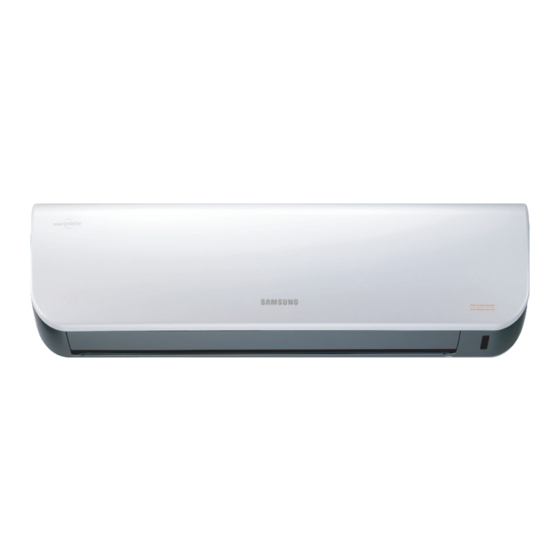
Samsung AQV09A Series Service Manual

Samsung AQV09A Series Service Manual

Indoor/outdoor unit
Hide thumbs Also See for AQV09A Series:
Table of Contents

Advertisement

AIR CONDITIONER
AQV09AAN, AQV12AAN
AQV09AAX, AQV12AAX
Refer to the service manual in the GSPN(see the rear cover) for the more information.
SPLIT-TYPE AIR CONDITIONER
INDOOR UNIT
Basic : AQV09VBA
AQV12VBA
Model : AQV09AA Series
AQV12AA Series
Model Code : AQV09AAN
AQV12AAN
CONTENTS
1. Precautions
2. Product Specifications
3. Disassembly and Reassembly
4. Troubleshooting
5. Exploded Views and Parts List
6. PCB Diagram and Parts List
7. Wiring Diagram
8. Schematic Diagram
9. Reference Sheet
OUTDOOR UNIT
AQV09AAX
AQV12AAX

Advertisement

Table of Contents
loading

Summary of Contents for Samsung AQV09A Series

  • Page 1 SPLIT-TYPE AIR CONDITIONER INDOOR UNIT OUTDOOR UNIT Basic : AQV09VBA AQV12VBA Model : AQV09AA Series AQV12AA Series Model Code : AQV09AAN AQV09AAX AQV12AAN AQV12AAX AIR CONDITIONER CONTENTS 1. Precautions 2. Product Specifications 3. Disassembly and Reassembly 4. Troubleshooting AQV09AAN, AQV12AAN 5.
  • Page 2: Table Of Contents

    4-3-13 No Power (completely dead)-Initial diagnosis (Not displayed) 4-18 ........4-3-14 The Outdoor unit power supply error (Not displayed) 4-19 ..........4-3-15 In case of heating at the cooling mode or cooling at the heating mode (Not displayed) 4-20 ... Samsung Electronics...
  • Page 3 ........................8-1.PCB Circuit Description ........................8-1-1.Indoor Unit ..............................8-1-2.Display ................................8-2 Outdoor Unit ............................ 8-2-1.EMI ..................................19. Reference Sheet ..........................9-1 Refrigerating Cycle Diagram ......................9-2 Index for Model Name ........................9-3 Distribution chart of the Pressure ....................Samsung Electronics...
  • Page 4: Precautions

     Check the distance between the product and the other electronic appliances such as TV, Video, and audio. It should be over 2m. - If not, it causes a bad picture quality or a noise.  Repairing the products by consumer should be strictly prohibited. - There is a danger of electric shock or fire due to incorrect disassembly. Samsung Electronics...
  • Page 5: Precautions For The Safety

    - There is a danger of electric shock.  In case the product will not be in use for a long time, the battery of remote control should be kept separately. - Leakage of inside fluid can cause break down of remote control. Samsung Electronics...
  • Page 6: Product Specifications

    Mode can help you sleep quickly and soundly and wake up refreshed. Mode  The Micro Plasma Ion mode creates strong purified zone in your room.  Silence Mode When you use the “Silence Mode”, you can experience extremely quiet operation of your air conditioner. Samsung Electronics...
  • Page 7: Modified Items Compared With Basic Model

    New model Indoor Indoor Design changed Grille inlet Indoor - LOGO design changed - Grille shape changed Using the new concept mechanism of the Indoor moving grille Indoor ASSY WINDOW DISPLAY Outdoor Cabinet part Outdoor Using double-sealed compressor felt Samsung Electronics...
  • Page 8: New Components To Be Applied

    2-1-3 New components to be applied Part New contents and characteristic Image MPI LAMP (New concept) DNA filter (New concept) - To intensify the Fresh air fuction Indoor Grille door (New concept) - preventing the infiltration of dust Cross flow fan (New application) Samsung Electronics...
  • Page 9: Characteristic Of Display

    2-1-4. Characteristic of display - BASIC:Good Morning - NEW:good’ sleep - BASIC:No Energy Saving Lamp - NEW:Display the Energy Saving function -BASIC:Display the MPI function by Character -NEW:Display the MPI function by LAMP’s brightness Samsung Electronics...
  • Page 10: The Comparative Specifications Of Product

    2-2 The Comparative Specifications of Product Development Model Comparative Model Item AQV09A series AQV12A series AQV09VBA AQV12VBA Indoor Unit Design Outdoor Unit Inverter Logo Cooling 0.99/2.50/3.20 0.99/3.50/4.00 0.99/2.50/3.50 0.99/3.50/4.20 Capacity (Low/Std/Max) Heating 0.99/3.40/4.50 0.99/4.00/5.20 0.85/3.50/5.00 0.85/4.00/5.50 Cooling 20/45/61 20/69/81 20/46/70...
  • Page 11: Accessory And Option Specifications

    2-3 Accessory and Option Specifications 2-3-1 Accessories Item Descriptions Code-No. Q'TY Remark Plate-hanger DB70-00819A Remote Control DB93-04700P Indoor Batteries for Remote Control DB47-90024A Unit User’s Manual DB98-28606A Installation Manual DB98-28611A Drain Plug DB67-20011A Outdoor Unit Rubber Leg DB73-20134A Samsung Electronics...
  • Page 12 Product Specifications Accessories(cont.) Item Descriptions Code-No. Q'TY Remark 4-wire Assembly Cable DB39-01092B Assembly Pipe, ø6.35mm DB96-10453B Assembly Pipe, ø9.52mm DB96-10453F Accessory PE T3 Foam Tube Insulation DB72-50165A Vinyl Tape, Width 50mm DB72-00459A Drain Plug DB67-20011A Rubber Leg DB73-20134A Samsung Electronics...
  • Page 13 M4x16 Tapping Screws 6002-000215 Drain Hose, length 2m DB62-00487A Putty 100g DB98-10568A 2-3-2 Filter Image Part name Code no Remark Pre-filter DB63-01826A wash in water DNA filter DB63-02010A Clean with vaccum cleaner or soft brush Deodorizing filter DB63-00616A Samsung Electronics...
  • Page 14: Troubleshooting

     Setting is not required if you must Every time you push the button, the display panel reads   a value which has a default.  . . .        repeatedly. Samsung Electronics...
  • Page 15 If all lamps of indoor unit are flickering, Plug out, plug in power plug again and press ON/OFF key to retry. If the unit is not working properly or all lamps are continuously flickering after setting the option code, see if the correct option code is set up for its model. Samsung Electronics...
  • Page 16 Operating Instructions and Installation OPTION ITEMS REMOCON SEG1 SEG2 SEG3 SEG4 SEG5 SEG6 SEG7 SEG8 SEG9 SEG10 SEG11 SEG12 MODEL AQV09AWAN AQV12AWAN Samsung Electronics...
  • Page 17: Display Error And Check Method

    Discharge temp minute, Continue page    sensor error set OFF After 1 Discharge over - Check the assembling statue of sensor parts    minute, Continue page temperature on the outdoor PCB CN54 PIN#3,#4 set OFF Samsung Electronics...
  • Page 18  GAS Leak error - Check the pipe leak minute, Continue page set OFF - Check the refrigerant of compressor After 1 capacity miss    - Reset remote-control option code minute, Continue page match set OFF Samsung Electronics...
  • Page 19: Fault Diagnosis By Symptom

    Correct the wrong wiring. and communication cable error? Is the connection of Correct the connection of communication cable normal? communication cable. Is it the outdoor Exchange the indoor/outdoor unit PCB. 2 Micom(Inverter + Main) model? Exchange the outdoor unit PCB. Samsung Electronics...
  • Page 20: Indoor Temperature Sensor ErrorWhen Is Diplayed

    35°C-6.94kΩ 40°C-5.83kΩ Connect the sensor to CN43, supply power, and measure the voltage of #1 and #2 of the CN43 connector. Below 0.5V? Poor ASS’Y PCB Replace Poor ASS’Y PCB Replace Over 4.9V? MICOM Error or Connector(CN43) check Samsung Electronics...
  • Page 21: Indoor Heat Exchanger Temperature Sensor ErrorWhen Is Diplayed

    35°C-6.94kΩ 40°C-5.83kΩ Connect the sensor to CN43, supply power, and measure the voltage of #1 and #2 of the CN43 connector. Below 0.5V? Poor ASS’Y PCB Replace Over 4.9V? Poor ASS’Y PCB Replace MICOM Error or Connector(CN43) check Samsung Electronics...
  • Page 22: Indoor Fan Motor Speed Detecting ErrorWhen Is Diplayed

    Test rod location Normal Voltage PCB CN72 Condition About AC pin #3 and #5 Fan operate 180V Replace Motor Motor Fan-Capacitor is out of order Fan-Capacitor Fan motor Fan motor is out of order. should be replaced. Samsung Electronics...
  • Page 23: Outdoor Temperature Sensor ErrorWhen Is Diplayed

    Exchange the sensor. (Refer to the R/T TABLE) Is the resistance value of sensor connection pull_up 5.1K? Exchange the PCB. Exchange the PCB. Normal operation Exit 400.0 350.0 300.0 250.0 200.0 150.0 100.0 50.0 4-10 Samsung Electronics...
  • Page 24: Coil Temperature Sensor ErrorWhen Is Diplayed

    Exchange the sensor. (Refer to the R/T TABLE) Is the resistance value of sensor connection pull_up 5.1K? Exchange the PCB. Exchange the PCB. Normal operation Exit 400.0 350.0 300.0 250.0 200.0 150.0 100.0 50.0 Samsung Electronics 4-11...
  • Page 25: Discharge Temperature Sensor ErrorWhen Is Diplayed

    Exchange the sensor. (Refer to the R/T TABLE) Is the resistance value of sensor connection pull_up 24K? Exchange the PCB. Exchange the PCB. Normal operation Exit 600.0 500.0 400.0 300.0 200.0 100.0 4-12 Samsung Electronics...
  • Page 26: The Outdoor Unit Fan ErrorWhen Is Diplayed

    Pull out the power cord and during the operation?(Square-Wave) execute the following step after 30 seconds. Disassemble the BLDC FAN Wire. Is the short between Exchange the PCB. the BLDC FAN Wires? Exchange the BLDC FAN MOTOR. Exchange the PCB. Samsung Electronics 4-13...
  • Page 27: Compressor Start ErrorWhen Is Diplayed

    Exchange the compressor. compressor (uv, vw, wu) normal? Is the compressor body and Exchange the compressor. interphase resistance insulated? Is the connection cable for the Correct the cable connection. compressor and power terminal normal? Exchange the PCB. 4-14 Samsung Electronics...
  • Page 28: Over Current) ErrorWhen Is Diplayed

    Is the position of temperature sensor Correct the sensor position or and the sensing value normal? exchange the sensor. Is the connection cable for Correct the cable connection. the compressor and power terminal normal? Exchange the PCB. Samsung Electronics 4-15...
  • Page 29: Total Current Sensor ErrorWhen Is Diplayed

    Pull out the power cord and exchange the PCB from the case after 30 seconds. Is the assembly of Micom and Exchange the PCB. peripheral circuit part good? Check again after assembly of PCB. 4-16 Samsung Electronics...
  • Page 30: Is Diplayed

    1, 2 correct after power supply? Is the capacitor(C101, C102, C103) Connect the connector. for DC-Link assembled in accordance the specification? Are R113, R114, R115 470kohm? Exchange the PCB. Is R116 14.3kohm? Exchange the Fan. Exchange the PCB. Normal operation Exit Samsung Electronics 4-17...
  • Page 31: No Power (Completely Dead)-Initial Diagnosis (Not Displayed)

    Replace fuse FUSE(F701) : T3.15[A]/250[V] Check the output of SMPS on the control board. Input power: AC230±15%[V] PCB should be replaced IC02 Input: DC12[V] IC02 output: DC5[V]  Check the setting temperature 4-18 Samsung Electronics...
  • Page 32: The Outdoor Unit Power Supply Error (Not Displayed)

    Is there no error at the insertion of PCB? Exchange the PCB. Exchange the PCB. Are the BLDC FAN Wire Is the +,- of C102 short? 1 and 3 short? Exchange the PCB. Exchange the BLDC FAN. Normal Operation Exit Samsung Electronics 4-19...
  • Page 33: In Case Of Heating At The Cooling Mode Or Cooling At The Heating Mode (Not Displayed)

    4 way valve coil. Dose the voltage of AC 220V Exchange apply to the connector of 4 way the outdoor PCB. valve coil during the operation? Go to the next page 4 way valve main body error 4-20 Samsung Electronics...
  • Page 34 Connect the connector. correctly? Check the resistance value Outdoor fan error of outdoor fan. Dose the voltage of DC300V apply to the connector of outdoor Check the motor wire. fan during the operation of outdoor unit? Outdoor PCB error Samsung Electronics 4-21...
  • Page 35: When The Up/Down Louver Motor Does Not Operate. (Initial Diagnosis) (Not Displayed)

    Voltage at pin #30~#34 of micom (IC04) Micom (IC04) is faulty. change?(Squarewave) Voltage at pin #2 ~ #5 of CN61(motor connector) Driver IC05/06 (ULN2003A) is faulty. change?(Squarewave) Up/Down louver motor is faulty. 4-22 Samsung Electronics...
  • Page 36: When The Remote Control Is Not Receiving

    4-3-18 The others 1. AC Line Zero Cross Signal OUT – Check the assembly condition of peripheral part of IC21, ZD21, ZD20 and D200 on the PCB. 2. Capacity miss match – Check again the indoor unit option code. Samsung Electronics 4-23...
  • Page 37: Pcb Inspection Method

    2) The fan motor of the indoor unit doesn’t run. • Fan Motor Connector(CN72) is faulty 3) The power voltage between terminal #3 and #5 • ASS’Y Main PCB is faulty of the connector(CN72) is 0V. • Connection is faulty 4-24 Samsung Electronics...
  • Page 38: Outdoor Detailed Inspection Procedure

    1) Is CN01 1, 3 over 250V? • Outdoor PCB Error 2) Is CN01 3, 5 within 1V~5V? • BLDC Motor Error 3) Is the voltage of CN01 6 changed? 4) Is the resistance of BLDC Motor 1, 3 opened after power off? Samsung Electronics 4-25...
  • Page 39: Main Part Inspection Method

    ∞, 0Ω . . . Open or Short Stepping Motor Measure the resistance between the red wire and each terminal wire with a tester. Normal About 300Ω at the normal temperature (20˚C ~ 30˚C) Abnormal ∞, 0Ω . . . Open or Short 4-26 Samsung Electronics...
  • Page 40 MEMO Samsung Electronics 4-27...
  • Page 41: Exploded Views And Parts List

    5. Exploded Views and Parts List 5-1 Indoor Unit 3-4-1 Samsung Electronics...
  • Page 42 MOTOR STEP DC12V, 600gf.cm DB62-05155A SEAL-INSUL TRAY FR EPS(30) DB69-00839A CUSHION-TRAY RH EPS(30) DB96-08235A ASSY EVAP-TOTAL ASSY DB61-03333A HOLDER-EVAP HIPS 0.3A,50/60Hz,35W,220/ DB31-00474A MOTOR FAN 240V,1350rpm DB94-00455A ASSY BEARING-RUBBER ASSY DB94-01556A ASSY-CROSS FAN ASSY DB61-03296A HOLDER-PIPE HIPS DB70-00819A PLATE-HANGER SGCC-M Samsung Electronics...
  • Page 43: Outdoor Unit

    5-2 Outdoor Unit 29-1 30-2 30-1 17-2 17-1 Samsung Electronics...
  • Page 44 FELT+PVC DB63-01933A FELT-COMP UPPER FELT+PVC DB63-01710A FELT-COMP UPPER FELT+PVC DB96-08389A ASSY-VALVE 4WAY ASSY 29-1 DB33-00002C SOLENOID-ASSY ASSY DB96-08390A ASSY-VALVE EEV ASSY 30-1 DB62-03916A VALVE-EXPANSION BODY FUJIKOKI, 1.4 30-2 DB62-03964A VALVE EXPAN-COIL FUJIKOKI, 1.4 DB93-05534B ASSY CONTROL OUT ASSY Samsung Electronics...
  • Page 45: Pcb Diagram And Parts List

    (-) output_1 output_1 #2:MPI driving signal #3:Motor driving signal #3:Motor driving signal output (+) output_2 output_2 #3:DV12V #4:Motor driving signal #4:Motor driving signal #4:MPI feedback signal output_3 output_3 input #5:Motor driving signal #5:Motor driving signal output_4 output_4 Samsung Electronics...
  • Page 46: Indoor Module Pcb

    6-1-3. Indoor DISPLAY PCB:DB93-05779A ① ② ① MPI DISPLAY CONNECTION ② DISPLAY CONNECTION #1:MPI Lamp driving signal #1:STB signal #2:Null #2:CLK signal #3:GND #3:LED driving signal #4:LED driving signal #5:DC5V #6:Null #7:Remocon signal input #8:DC12V #9:MPI Lamp driving signal Samsung Electronics...
  • Page 47: Outdoor Main Pcb

    COND Temperature #1:EEV driving signal 미사용 Sensor #2:EEV driving signal #1:Outdoor temperature #3:EEV driving signal sensing #4:EEV driving signal #2:GND #5:EEV driving signal #3:Discharge tempera- #6:DC12V ture sensing #4:GND #5:Cond. temperature sensing #6:GND ⑨Reactor Connector Wire ⑩Compressor Wire Samsung Electronics...
  • Page 48: Outdoor Emi Pcb

    6-1-5. Outdoor EMI PCB:DB93-04264A ⑤ ③ ② ④ ① ①, ④ Power N Wire ②, ⑤Power L Wire ③Earth Wire Samsung Electronics...
  • Page 49 3711-000999 CONNECTOR-HEADER BOX,5P,1R,2.5mm,STRAIGHT,SN CN63 3711-004484 CONNECTOR-HEADER BOX,5P,1R,2mm,STRAIGHT,SN CN6601 3711-000941 HEADER-BOARD TO CABLE BOX,4P,1R,2.5mm,STRAIGHT,SN CN72 3711-000262 CONNECTOR-HEADER 1WALL,3P,1R,7.92MM,STRAIGHT,SN,W CN91(1-9) 3711-004712 CONNECTOR-HEADER BOX,9P,1R,2MM,STRAIGHT,SN,NTR 175022-1(AMP),ST780400(KET),TP,170 DB39-01270C WIRE - #1015 18 AWG mm,BLK 1200nF,+10- CR71 2301-001251 C-FILM,LEAD-PPF 5%,450V,BK,38x18x30mm,3 D4201 0402-000137 DIODE-RECTIFIER 1N4007,1KV,1A,DO-41,TP Samsung Electronics...
  • Page 50 R-CHIP 4.7Kohm,5%,1/10W,TP,1608 R402 2007-000084 R-CHIP 4.7Kohm,5%,1/10W,TP,1608 R301 2007-000090 R-CHIP 10Kohm,5%,1/10W,TP,1608 R302 2007-000090 R-CHIP 10Kohm,5%,1/10W,TP,1608 R406 2007-000090 R-CHIP 10Kohm,5%,1/10W,TP,1608 R501 2007-000090 R-CHIP 10Kohm,5%,1/10W,TP,1608 R6105 2007-000090 R-CHIP 10Kohm,5%,1/10W,TP,1608 R6602 2007-000090 R-CHIP 10Kohm,5%,1/10W,TP,1608 R303 2007-000116 R-CHIP 120ohm,5%,1/10W,TP,1608 R305 2007-000116 R-CHIP 120ohm,5%,1/10W,TP,1608 Samsung Electronics...
  • Page 51 280V, 680V,4500A,17.5x6.5mm,TP,INR14D68 VA71 1405-000160 VARISTOR 1KORSY X0101 2802-001179 RESONATOR-CERAMIC 4MHZ,0.5%,BK,8X3X5.5MM XC71 2301-001220 C-FILM,LEAD-PPF 100nF,10%,275V,BK,18x6x12,15 XC72 2301-001220 C-FILM,LEAD-PPF 100nF,10%,275V,BK,18x6x12,15 ZD4201 0403-000252 DIODE-BRIDGE DF06S,600V,1A,SMD-4,TP BZX84-C11,10.4-11.6V,350mW,SOT- ZD4202 0403-001285 DIODE-ZENER 23,TP ZD4203 0403-000258 DIODE-ZENER BZX84C5V6,5.6,225mW,SOT-23,TP SUB PBA DB93-04256B INDOOR SUB PBA AC_COM Samsung Electronics...
  • Page 52: Electrical Parts List

    Specification Q’ty SA/SNA 0401-000005 DIODE-SWITCHING 1N4148,75V,150mA,DO-35,TP RM01 0609-001204 Module Remocon HORIZONTAL,6.5mm,TR 2001-000793 R-CARBON 47OHM,5%,1/8W,AA,TP,1.8X3.2MM 2202-000173 C-CERAMIC,MLC-AXIAL 1nF,10%,50V,Y5P,-,1.9x3.5mm,- 2202-000780 C-CERAMIC,MLC-AXIAL 100nF,+80-20%,50V,Y5V,-,3.5x19mm,- 2401-003107 C-AL 47uF,20%,16V,GP,TP,5x7,5 SW01 3404-001220 SWITCH-TACT 12V,50mA,160gf,6.1x6.1x5.0mm,SPST CN01 3711-004067 HEADER-BOARD TO CABLE BOX,4P,1R,2mm,ANGLE,SN,NTR DB41-00555A PCB-MODULE VIVACH ,FR-1,-,Revision 1,1.6T,25*40,-,-,-,SSEC Samsung Electronics...
  • Page 53 2007-000076 R-CHIP 330ohm,5%,1/10W,TP,1608 R508 2007-000076 R-CHIP 330ohm,5%,1/10W,TP,1608 R553 2007-000076 R-CHIP 330ohm,5%,1/10W,TP,1608 R303 2007-000077 R-CHIP 470ohm,5%,1/10W,TP,1608 R304 2007-000077 R-CHIP 470ohm,5%,1/10W,TP,1608 R323 2007-000077 R-CHIP 470ohm,5%,1/10W,TP,1608 R342 2007-000077 R-CHIP 470ohm,5%,1/10W,TP,1608 R302 2007-000119 R-CHIP 560ohm,5%,1/10W,TP,1608 R207,R208 2007-000080 R-CHIP 2Kohm,5%,1/10W,TP,1608 2007-000080 R-CHIP 2Kohm,5%,1/10W,TP,1608 Samsung Electronics...
  • Page 54 90.9Kohm,1%,1/4W,TP,3216 R202 2007-002667 R-CHIP 90.9Kohm,1%,1/4W,TP,3216 R203 2007-002667 R-CHIP 90.9Kohm,1%,1/4W,TP,3216 R204 2007-002667 R-CHIP 90.9Kohm,1%,1/4W,TP,3216 R110 2007-008023 R-CHIP 100Kohm,5%,1W,TP,6432 R111 2007-008023 R-CHIP 100Kohm,5%,1W,TP,6432 R112 2007-008023 R-CHIP 100Kohm,5%,1W,TP,6432 C106 2201-000322 C-CERAMIC,DISC 2.2NF,10%,2KV,Y5P,TP,13X5MM,10 C107 2201-000322 C-CERAMIC,DISC 2.2NF,10%,2KV,Y5P,TP,13X5MM,10 C304 2201-000322 C-CERAMIC,DISC 2.2NF,10%,2KV,Y5P,TP,13X5MM,10 Samsung Electronics 6-10...
  • Page 55 100nF,10%,50V,X7R,TP,1608,- C518 2203-005249 C-CER,CHIP 100nF,10%,50V,X7R,TP,1608,- C519 2203-005249 C-CER,CHIP 100nF,10%,50V,X7R,TP,1608,- C553 2203-005249 C-CER,CHIP 100nF,10%,50V,X7R,TP,1608,- C554 2203-005249 C-CER,CHIP 100nF,10%,50V,X7R,TP,1608,- C560 2203-005249 C-CER,CHIP 100nF,10%,50V,X7R,TP,1608,- C561 2203-005249 C-CER,CHIP 100nF,10%,50V,X7R,TP,1608,- C563 2203-005249 C-CER,CHIP 100nF,10%,50V,X7R,TP,1608,- C565 2203-005249 C-CER,CHIP 100nF,10%,50V,X7R,TP,1608,- C568 2203-005249 C-CER,CHIP 100nF,10%,50V,X7R,TP,1608,- 6-11 Samsung Electronics...
  • Page 56 ASC712,5HP INVERTER,-,-40~150 SENSOR DB95-00599A ASSY-IPM KFR-35GW/GPI,INVERTER BD01 DB98-16586A ASSY-DIODE GS1B2560 D101 DB98-16591A ASSY-DIODE RECTIFIER FEP30JP PT02 DB98-20602A ASSY-PULSE TRANS KFR-35GW/GPI,INVERTER R106 DB98-20665A ASSY-RESISTOR KFR-35(25)GW/GPI,1.8k F 1608 IC81 DB98-20678A ASSY-PHOTOCOUPLER KFR-35(25)GW/GPI,TLP351 IC11 DB98-20679A ASSY-FPS KFR-35(25)GW/GPI,FSDH321 C101 DB98-21655A ASSY-CAP KFR-35(25)GW,KMH400VS470 Samsung Electronics 6-12...
  • Page 57 DB91-00501A EEPROM DATA IC501 1103-001038 IC-EEPROM 93LC66,4KBIT,256X16BIT,SOP,8P,5X4MM,-,2 DB91-00500A EEPROM DATA IC501 1103-001038 IC-EEPROM 93LC66,4KBIT,256X16BIT,SOP,8P,5X4MM,-,2 EARTH DB39-00514F CONNECT WIRE 4WAY DB93-04349A CONNECT WIRE COMM-N DB93-04348C CONNECT WIRE COMP DB93-04336A CONNECT WIRE REACTOR DB93-04348B CONNECT WIRE 160*140 DB41-00626A PCB FR-4 6-13 Samsung Electronics...
  • Page 58 560V,4500A VA09 1405-000154 VARISTOR 560V,4500A C001 2201-000540 C-CERAMIC,DISC 4.7nF,250V C002 2201-000540 C-CERAMIC,DISC 4.7nF,250V C010 2201-000540 C-CERAMIC,DISC 4.7nF,250V C011 2201-000540 C-CERAMIC,DISC 4.7nF,250V C003 2301-001285 C-FILM,LEAD-PPF 680nF,275V C004 2301-001325 C-FILM,LEAD-PPF 330nF,275V EYELEY 6042-001009 EYELET 4.0*3.0*2.3mm,FT00,FT01 EYELEY 6042-001012 EYELET 5.0*3.0*4.3mm,TB_L,TB_N;AC_L,AC_N Samsung Electronics 6-14...
  • Page 59: Wiring Diagram

    Grill Motor Part Communication Part Blade swing Motor Part Communication Part Remote control & Switch signal Receiving Part BLDC Motor Part EMI PCB Part Out/Discharge/Cond Sensor Part ������� 4Way V/V Part ������ Reactor Part Copressor Part EEV Part Samsung Electronics Samsung Electronics...
  • Page 60: Schematic Diagram

    8-1-1.Indoor Unit SMPS PART INDOOR FAN CONTROL ZERO CROSSING PART INDOOR TEMPERATURE SENSOR MPI PART BUZZER PART SUB PCB CONNECTOR DISPLAY PART STEP MOTOR PART AUTO ROOF SHUTTER PART PROGRAM DOWNLOAD PART KEY/REMOCON SIGNAL PART COMMUNICATION PART Samsung Electronics Samsung Electronics...
  • Page 61: 8-1-2.Display

    8-1-2.Display Samsung Electronics Samsung Electronics...
  • Page 62 8-2.Outdoor Unit SMPS PART BLDC FAN CONTROL ZERO CROSSING PART TEMPERATURE SENSOR COMMUNICATION PART INVERTER PART Samsung Electronics Samsung Electronics...
  • Page 63: 8-2-1.Emi

    8-2-1.EMI Samsung Electronics Samsung Electronics...
  • Page 64: Reference Sheet

    9-1 Refrigerating Cycle Diagram Indoor Unit Outdoor Unit 2 way valve Expansion valve Liquid side Heat Exchanger (Evaporator) Heat Exchanger (Condenser) Cross Fan Gas side 4 way valve 3 way valve Cooling Compressor Heating Gas Leak Check Point Samsung Electronics...
  • Page 65: Index For Model Name

    ③ : Use the " ③ " digit for classification between indoor and outdoor. Indoor  "N" & Outdoor  "X". ④ : Use the “ ④ ” digit for KD models. "CKD"  "1" & "SKD"  "2". Samsung Electronics...
  • Page 66: Distribution Chart Of The Pressure

    2 7 ℃ 2 4 ℃ 2 1 ℃ Outdoor temperature [ ℃ ] AQV12A*A Indo o r Temperature 3 2 ℃ 2 9 ℃ 2 7 ℃ 2 4 ℃ 2 1 ℃ Outdoor temperature [ ℃ ] Samsung Electronics...
  • Page 67: Samsung Electronics

    Asia http://asia.samsungportal.com Mideast & Africa http://mea.samsungportal.com This Service Manual is a property of Samsung Electronics Co., Ltd. © Samsung Electronics Co., Ltd. Oct. 2007. Any unauthorized use of Manual can be punished under applicable Code No. DB98-28739A(1) International and/or domestic law.

Table of Contents