Table of Contents
Advertisement
INSTRUCTIONS
BX41
SYSTEM MICROSCOPE
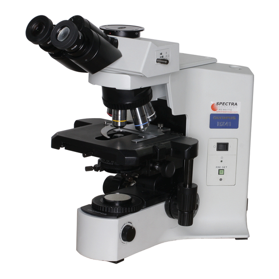
This instruction manual is for the Olympus System Microscope Model BX41. To ensure the safety,
obtain optimum performance and to familiarize yourself fully with the use of this microscope, we
recommend that you study this manual thoroughly before operating the microscope. Retain this
instruction manual in an easily accessible place near the work desk for future reference.
A X 9 8 5 3
Advertisement
Table of Contents

Related Manuals for Olympus BX41


Summary of Contents for Olympus BX41
- Page 1 BX41 SYSTEM MICROSCOPE This instruction manual is for the Olympus System Microscope Model BX41. To ensure the safety, obtain optimum performance and to familiarize yourself fully with the use of this microscope, we recommend that you study this manual thoroughly before operating the microscope. Retain this instruction manual in an easily accessible place near the work desk for future reference.
-
Page 2: Table Of Contents
BX41 CONTENTS Correct assembly and adjustments are critical for the microscope to exhibit its full performance. If you are going to assemble the microscope yourself, please read section 7, “ASSEMBLY” (pages 26 to 28) carefully. IMPORTANT — Be sure to read this section for safe use of the equipment. —... - Page 3 UIS eyepieces, objectives and condensers for the BX2 series. (Some of the modules designed for the BX series are also usable. For details, please consult Olympus or the catalogue.) Less than optimum perfor- mance may result if inappropriate accessories are used.
- Page 4 4. The BX41 can be used with up to two intermediate attachments (e.g. a U- CA magnification changer, U-EPA2 eyepoint adjuster, etc.). For restrictions when using two intermediate attachments, make sure to read the in- struction manual provided with the respective intermediate attachments.
-
Page 5: Maintenance And Storage
Maintenance and Storage 1. Clean all glass components by wiping gently with gauze. To remove fingerprints or oil smudges, wipe with gauze slightly moistened with a mixture of ether (70%) and alcohol (30%). Since solvents such as ether and alcohol are highly flammable, they must be handled carefully. Be sure to keep these chemicals away from open flames or potential sources of electrical sparks ––... -
Page 6: Product View And Parts
BX41 NOMENCLATURE } If you have not yet assembled the microscope, read section 7, “ASSEMBLY” (pages 26 to 28). Interpupillary distance adjustment scale (Page 13) Allen screwdriver (accommodation position) Condenser height adjustment knob (Page 16) Diopter adjustment ring Main switch (Page 1) -
Page 7: Transmitted Light Brightfield Observation Procedure
TRANSMITTED LIGHT BRIGHTFIELD OBSERVATION PROCEDURE (Controls Used) (Page) @Main switch Set the main switch to “ I ” (ON) and adjust the brightness. ²Brightness adjustment knob (P. 7) Select the light path (trinocular tube). ³Light path selector knob (P. 14) |Slide holder (P. - Page 8 BX41 ‡ ³ (Trinocular observation tube only) Š … ‰ Œ ƒ ‹ † ™ š † ² } Copy the observation procedure pages on separate sheets and post it near your microscope.
-
Page 9: Using The Controls
USING THE CONTROLS 3-1 Base Voltage Indication (Fig. 4) 1. Turn the brightness adjustment knob @ clockwise to increase the volt- age and make illumination brighter. 2. The numerals ² below the knob indicate the approximate voltage. ² Fig. 4 Using the Light Intensity Preset Switch (Fig. - Page 10 BX41 Using the Filter Cassette (Figs. 7 - 10) Loading Filters into Filter Cassette }The filter cassette accommodates filters with a diameter of 45 mm and thickness of 2.7 mm or less. }The filter cassette has two filter levels on the right side and one on the left side.
-
Page 11: Focusing Block
3-2 Focusing Block Replacing the Fine Adjustment Knob (Fig. 11) # The fine adjustment knob has been attached on the right side at the factory. }The fine adjustment knob is designed detachable to prevent interference with hand during manipulation of the X-and Y-axis knobs. Usually attach the knob on the opposite side to the X- and Y-axis knobs. -
Page 12: Stage
BX41 3-3 Stage Placing the Specimen ² # The dimensions of the slide glass should be 26 x 76 mm with thick- ness of 0.9 to 1.4 mm, and the cover glass should have thickness of 0.17 mm. # When observing very large specimens, remove the slide holder and place the specimen directly on the stage. - Page 13 Adjusting the X- and Y-Axis Knob Tension (Fig. 17) 1. Hold the X-axis knob @ and slide up the Y-axis knob ² up to expose the adjustment knobs. ² 2. Turning the X-axis adjustment knob ³ or Y-axis adjustment knob | clock- wise (in the direction of the arrow) increases the tension and counter- clockwise decreases it.
-
Page 14: Rotating The Stage
BX41 Rotating the Stage (Fig. 18) 1. Slightly loosen the stage clamping screw @. 2. The stage can be rotated both clockwise and counterclockwise by the stage clamping screw. # A click may be heard and felt during rotation. However, this is due to the construction of the substage and does not indicate a malfunc- tion. -
Page 15: Observation Tube
3-4 Observation Tube Adjusting the Interpupillar Distance (Fig. 21) While looking through the eyepieces, adjust for binocular vision until the left and right fields of view coincide completely. The index dot · indicates the interpupillary distance. }Note your interpupillary distance so that it can be quickly duplicated. Fig. -
Page 16: Using Eyepiece Micrometer Disks
BX41 Using Eyepiece Micrometer Disks (Fig. 25) Eyepiece micrometer disks can be inserted into WH10X-H (or WH10X) eyepieces. Use 24 mm diam. x 1.5 mm micrometer disks. Following Fig. 25, unscrew the micrometer mounting frame ² from the ² eyepiece and place a micrometer disk @ into the mounting frame. The engraving on the micrometer disk should face downward into the mi- crometer mounting frame. -
Page 17: Adjusting The Tilt
Adjusting the Tilt (with the U-TBI3) (Fig. 27) }Adjust the height and tilt of the observation tube to obtain the most com- fortable viewing position. Holding the binocular section with both hands, raise or lower it to the desired position. # Never attempt to force the binocular section past the upper or lower stop position. -
Page 18: Condenser
BX41 3-5 Condenser Centering the Condenser (Figs. 29 & 30) 1. Turn the condenser height adjustment knob @ to raise the condenser to its upper limit. 2. Focus on the specimen using the 10X objective. # When using the U-SC3 swing-out condenser, move the top lens into ³... - Page 19 Aperture Iris Diaphragm (Figs. 31 & 32) Aperture iris 70-80% diaphragm image · The aperture iris diaphragm determines the numerical aperture of the 30-20% illumination system. Matching the numerical aperture of the illumination system with that of the objective provides better image resolution and contrast, and also increases the depth of focus.
-
Page 20: Immersion Objectives
BX41 3-6 Immersion Objectives # Be sure to use the provided Olympus Immersion oil. Using Immersion Objectives (Fig. 33) 1. Focus on the specimen with objectives in the order of lower-power to higher-power ones. 2. Before engaging the immersion objective, place a drop of provided immersion oil onto the specimen at the area to be observed. -
Page 21: Troubleshooting Guide
Under certain conditions, performance of the unit may be adversely affected by factors other than defects. If problems occur, please review the following list and take remedial action as needed. If you cannot solve the problem after checking the entire list, please contact your local Olympus representative for assistance. Problem... - Page 22 BX41 Problem Cause Remedy Page Recommended immersion oil is not Use the provided immersion oil. used. Dirt/dust on specimen. Clean it. Dirt/dust on condenser Inappropriate object side or cover glass Replace with glass of recommended thickness. thickness. f ) One side of image is blurred.
- Page 23 Problem Cause Remedy Page d) Coarse adjustment will not go all Pre-focusing lever is locked at a too low Unlock pre-focusing lever. the way up. height. e) Coarse adjustment will not go all Condenser holder is too low. Raise condenser holder. the way down.
-
Page 24: Specifications
BX41 SPECIFICATIONS Item Specification 1. Optical system UIS (Universal Infinity System) optical system Built-in transmitted Koehler illumination 2. Illumination 6V 30W halogen bulb (pre-centered) 6V30WHAL (PHILIPS 5761) (Average life time: Approximately 100 hr. when used as directed) Light intensity voltage range: 2V or less to 5.9 V DC (continuous) Light intensity preset button (voltage adjustment range: 2V or less to 5.9 V DC) - Page 25 Item Specification 7. Condenser Type U-AC2 U-SC3 U-AAC Abbe Swing-out Achromat/ Aplanat N.A. 1.10 0.9 - 0.1 1.40 Aperture iris dia- With numerical aperture scale phragm Objective range 4X (for FN 22 widefield), 1.25X (for FN 22 10X - 100X (for FN 26.5 10X - 100X widefield), super widefield)
-
Page 26: Optical Characteristics
The figure on the right shows the performance data engraved on the objectives. Numerical aperture NOTE Refer to the latest catalogue or consult your local Olympus representative for the updated information on the eyepieces Mechanical tube length Cover glass thickness and objectives that can be combined with this microscope. - Page 27 Eyepiece Optical Cover Reso- character WH10X (FN22) WH15X (FN14) glass Magni- W.D. lution N.A. Remark thick- fication (mm) Depth Depth (µm) Total Field Total Field ness of focus of focus mag. of view mag. of view Objective (µm) (µm) MPlan Apo No Cover 100XO 1.40...
-
Page 28: Assembly
The module numbers shown in the following diagram are merely the typical examples. For the modules with which the module numbers are not given, please consult your Olympus representative or the catalogues. # When assembling the microscope, make sure that all parts are free of dust and dirt, and avoid scratching any parts or touching glass surfaces. -
Page 29: Installing Bulb And Lamp Socket
7-2 Detailed Assembly Procedures Installing the Bulb and Lamp Socket (Figs. 35 & 36) Use only the designated bulb 6V30WHAL (PHILIPS 5761). 1. Holding the bulb @ with gloves or a piece of gauze, insert the bulb pins ² straight and fully into the pin holes ³ on the lamp socket. # To prevent reduced bulb life or cracking, do not touch the bulb with ²... - Page 30 ” (OFF) before con- ³ necting the power cord. Always use the power cord provided by Olympus. IF no power cord is provided with the microscope, please select the proper power cord by referring to section “PROPER SELECTION OF THE POWER ²...
-
Page 31: Proper Selection Of The Power Supply Cord
If no power supply cord is provided, please select the proper power supply cord for the equipment by referring to “ Specifications ” and “ Certified Cord ” below: CAUTION: In case you use a non-approved power supply cord for Olympus products, Olympus can no longer warrant the electrical safety of the equipment. - Page 32 BX41 Table 2 HAR Flexible Cord APPROVAL ORGANIZATIONS AND CORDAGE HARMONIZATION MARKING METHODS Alternative Marking Utilizing Printed or Embossed Harmoniza- Black-Red-Yellow Thread (Length tion Marking (May be located on Approval Organization of color section in mm) jacket or insulation of internal wir-...
- Page 33 MEMO...
- Page 34 2-43-2,Hatagaya, Shibuya-ku, Tokyo, Japan Postfach 10 49 08, 20034, Hamburg, Germany 2 Corporate Center Drive, Melville, NY 11747-3157, U.S.A. 491B River Valley Road, #12-01/04 Valley Point Office Tower, Singapore 248373 2-8 Honduras Street, London EC1Y OTX, United Kingdom. 104 Ferntree Gully Road, Oakleigh, Victoria, 3166, Australia This publication is printed on recycled paper.
Need help?
Do you have a question about the BX41 and is the answer not in the manual?
Questions and answers