Table of Contents
Advertisement
Quick Links
Advertisement
Table of Contents

Related Manuals for Antec Dark fleet DF-10


Summary of Contents for Antec Dark fleet DF-10
- Page 1 D F - 1 0 DVANCED AMING ORCE LEET S E R A N U A L...
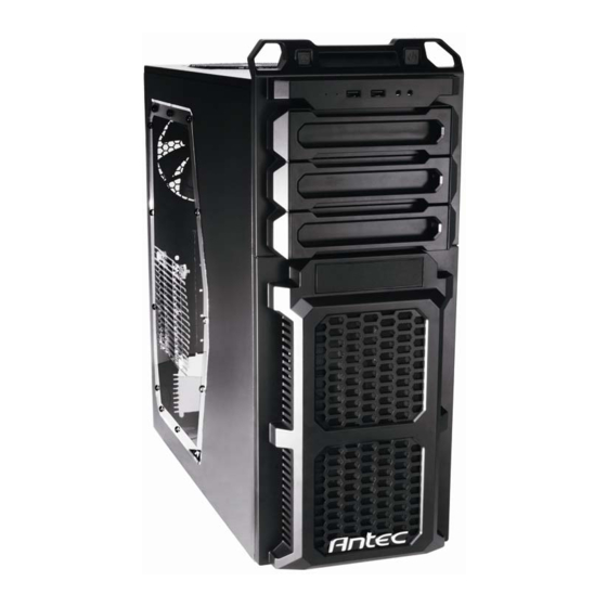
- Page 2 With a bevy of in-demand features and a rugged exterior, all at a supremely attractive price, the Dark Fleet DF-10 is more than just a low price - it’s the value case that gives you more for your money.
-
Page 3: Table Of Contents
ABLE OF ONTENTS 1: I ECTION NTRODUCTION Getting to know your case ..................5 Case specifications ....................... 6 Before you begin ......................7 2: H ECTION ARDWARE INSTALLATION Setting up ........................9 Motherboard installation .................... 11 Standard ATX power supply installation ..............13 Cable management ...................... -
Page 4: Section 1 Introduction
ECTION NTRODUCTION ... -
Page 5: Getting To Know Your Case
ETTING TO KNOW YOUR CASE Drive Bays Hardware Mounts 1 5.25" drive bays 6 Motherboard standoffs (pre‐installed) 2 3.5" drive bays 7 Power supply mounts 3 2.5" internal SSD bay 8 Front I/O ports Cooling 4 140 mm top TwoCool™ fan 5 120 mm rear TwoCool™ fan ... -
Page 6: Case Specifications
ASE PECIFICATIONS Mid-tower Matte black OLOR 19.2″ (H) x 7.8″ (W) x 19.6″ (D) IMENSIONS 488 mm (H) x 198 mm (W) x 497 mm (D) 15.1 lbs / 6.9 kg EIGHT 1 x top 140 mm TwoCool™ fan OOLING 1 x rear 120 mm TwoCool™... -
Page 7: Before You Begin
OU EGIN In order to ensure that your building experience with the Dark Fleet DF-10 will be a positive one, please take note of the following: While working inside your Dark Fleet DF-10, keep your case on a flat, stable surface. Make sure your build area is clean, well-lit, and free of dust. -
Page 8: Section 2 Hardware Installation
ECTION ARDWARE NSTALLATION... -
Page 9: Setting Up
ETTING Put the case upright on a flat, stable surface so that the rear panel (power supply and expansion slots) is facing you. To remove the left and right side panels, remove these thumbscrews:... - Page 10 Now rest your case with the left side up. Here’s what we’ll be working with first: A – Power supply mounts B – 5.25” drive bay area C – 3.5” drive bay area D – Front panel wiring E – I/O panel Note: Do not use your fingernails to pry or lift the panels.
-
Page 11: Motherboard Installation
OTHERBOARD NSTALLATION Before proceeding: Check the manual for your CPU cooler to find out if there are steps you must do before installing the motherboard Make sure you have the correct I/O panel for your motherboard. If the panel provided with the case isn’t suitable, please contact your motherboard manufacturer for the correct I/O panel. - Page 12 Now remove your motherboard by lifting it up. Lift your motherboard out to install the standoffs. Install standoffs as needed and put the motherboard back in. Screw in your motherboard to the standoffs with the provided Phillips-head screws. Caution: Make sure to remove any unused motherboard standoffs. They may come into contact with the back of the motherboard and may electrify your case exterior if left connected.
-
Page 13: Standard Atx Power Supply Installation
Note: The DF-10 comes with a CPU cutout on the motherboard tray, which will allow you to change your CPU heatsink without removing the motherboard. TANDARD OWER UPPLY NSTALLATION The DF-10 can accommodate a standard-size ATX power supply. With the case upright, place the power supply on the bottom of the case. -
Page 14: Cable Management
Use these screws to secure your power supply to the case. Note: Power supplies with fans on the bottom of the power supply will need to be mounted so that the fan is facing the top of the case. The DF-10 provides mounting holes for power supplies with standard mounting layouts to be installed right side up or upside down. -
Page 15: Internal 3.5" Device Installation
3.5” NTERNAL EVICE NSTALLATION The portion of the bezel covering the internal 3.5” drive bays can be removed. With the left side of the case facing you, push on the tabs near the front behind the bezel away from you to release the bezel (see picture). -
Page 16: External 3.5" Device Installation
3.5” XTERNAL EVICE NSTALLATION There is one external 3.5” drive bay under the 5.25” drive bays. Remove this drive bay cover. Carefully remove the 3.5” drive bay cover from the bezel. Load the drives from the front, lining them up to the front of the drive cage. -
Page 17: Internal 2.5" Device Installation
Slide your 5.25” device into the bay from the front of the case. 5.25” device installation Secure the drive into position in the drive bay using the provided screws on each side of the drive. Mount any other 5.25” devices accordingly. Connect the appropriate power and data cables to your device(s). -
Page 18: Section 3 Front I/Oports
I/O ECTION RONT ORTS... -
Page 19: Usb 2.0
Connect the front I/O panel USB cable to the USB header pin on your motherboard. Check your motherboard user’s manual to ensure that it matches the table below: Signal Names Signal Names USB Power 1 USB Power 2 Negative Signal 1 Negative Signal 2 Positive Signal 1 Positive Signal 2... -
Page 20: Power Switch / Reset Switch / Hard Disk Drive Led Connectors
OWER WITCH ESET WITCH ARD ISK RIVE ONNECTORS Connected to your front panel are LED and switch leads for power, reset, and HDD LED activity. Attach these to the corresponding connectors on your motherboard. Consult your motherboard manual for specific pin header locations. -
Page 21: Section 4: Cooling System
ECTION OOLING YSTEM... -
Page 22: Included Fans
NCLUDED FANS Standard fans on the DF-10: A – 1 x 120 mm rear TwoCool™ blue LED fan B – 1 x 140 mm top TwoCool™ fan Rear fan control panel... -
Page 23: Top 140 Mm Twocool™ Fan
High if you choose to connect the fan(s) to a fan control device or to the Fan-Only connector found on some Antec power supplies. A fan control device regulates the fan speed by varying the voltage, which may start as low as 4.5V to 5V. Connecting a TwoCool™... -
Page 24: Optional Fans
There is also space to mount two fans in the bezel in front of the 3.5” internal drive bays for hard drive cooling. We recommend using Antec 120 mm TriCool™ fans and setting the speed to Low. These fans brings cool air into the case. - Page 25 US & Canada 1-800-22ANTEC customersupport@antec.com Europe +31 (0) 10 462-2060 europe.techsupport@antec.com www.antec.com © Copyright 2010 Antec, Inc. All rights reserved. All trademarks are the property of their respective owners. Reproduction in whole or in part without written permission is prohibited.
Need help?
Do you have a question about the Dark fleet DF-10 and is the answer not in the manual?
Questions and answers