Table of Contents
Advertisement
Advertisement
Table of Contents

Related Manuals for Antec 902


Summary of Contents for Antec 902
- Page 1 Nine Hundred Two User’s Manual...
-
Page 2: Table Of Contents
Table of Contents Introduction 1.1 Case Specifications………………...……………...…………...… 2 1.2 Diagram……………………………………………...…...……...… 2 Hardware Installation Guide 2.1 Setting Up……….…...……... 3 2.2 Power Supply Installation.…………………...….…...…. 3 2.3 Motherboard Installation………………………………...…...…. 3 2.4 Flexi-Drive Bay System…………………..…... 4 2.5 Internal 3.5” Device Installation…………………….…...…... 4 2.6 External 3.5” Device Installation………………...……...…. 5 2.7 External 5.25”... - Page 3 NeoPower or Signature Series power supplies for the latest ATX specification compliance, broad compatibility, and power-saving capability. Although care has been taken to prevent sharp edges in your Antec case, we strongly recommend taking the appropriate time and care when working with it. Avoid hurried or careless motions.
-
Page 4: Case Specifications
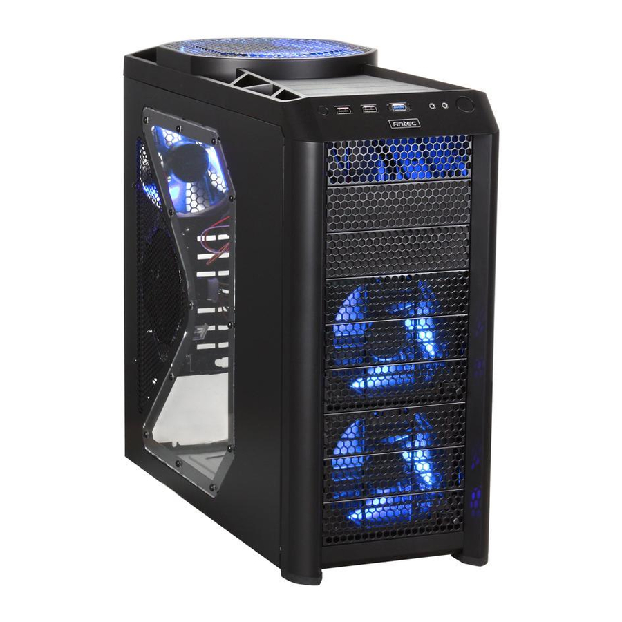
1.1 Case Specifications Case TypeColor Color Dimensions Weight Cooling Drive Bays Expansion Slots Motherboard Size Front I/O Panel 1.2 Diagram 120mm rear TriCool™ exhaust fan 200mm top TriCool™ exhaust fan 2 front 120mm TriCool™ intake fans 1 middle 120mm fan bracket Washable air filters Motherboard mount: Mini-ITX, microATX or Standard ATX Power supply mount... -
Page 5: Hardware Installation Guide
Hardware Installation Guide 2.1 Setting Up Place the case upright on a flat, stable surface so that the rear panel (power supply and expansion slots) is facing you. Remove the panel thumbscrews from the side panel and open it by sliding it towards you.Note: Place the panel thumbscrews carefully aside as they are NOT interchangeable with the HDD cage thumbscrews. -
Page 6: Flexi-Drive Bay System
2.4 Flexi-Drive Bay System The Nine Hundred Two comes with nine 5.25” external drive bays at the front of the case. There are two HDD cages pre-installed inside the bottom six 5.25” bays. Each HDD cage occupies three consecutive 5.25” drive bays and can house three hard disk drives. For maximum flexibility you can mount the HDD cage anywhere within the external drive bays (i.e., you are not limited to the bottom six bays). -
Page 7: External 3.5" Device Installation
Connect the appropriate connector(s) from the power supply to the device(s). Leave some slack in the connections so that you can easily access the fan filters for cleaning. There is a 120mm fan pre-installed onto each cage. Connect the 4-pin connector to the power supply. -
Page 8: Cable Management Compartment
2.8 Cable Management Compartment There is a cable management compartment between the motherboard and right side panel. You can tuck or route excess cables in this compartment. Remove both side panels. Choose the cables you would like to pass through the holes behind the motherboard tray and pull them out of the power supply chamber towards the right side of the case. -
Page 9: Esata Port
You will find a SATA connector on a cable attached to the front ports. This internal SATA connector is designed to connect to a standard SATA connector on your motherboard. This will allow high-speed external hard disk enclosures such as the Antec MX-1 to run at the same speeds as internally installed hard disks. -
Page 10: Rewiring Motherboard Header Connections
3.5 Rewiring Motherboard Header Connection There may come a time when you need to reconfigure the pin-out of a motherboard header connector. Examples could be for your USB header, audio input header, or some other front panel connector such as the Power Button connector. Before performing any work, please refer to your motherboard manual or your motherboard manufacturer’s website to be sure of the pin-out needed for your connector. -
Page 11: Front/Rear Tricool™ Led Fans
High if you choose to connect the fan(s) to a fan control device or to the Fan-Only connector found on some Antec power supplies. A fan control device regulates the fan speed by varying the voltage, which may start as low as 4.5V to 5V. -
Page 12: Optional Fans
There are two optional 120mm fan mounts—the side fan (on the left side panel) and the middle fan (at the rear end of the HDD cage). We recommend using Antec 120mm TriCool™ fans and setting the speed to Low. These two fans should be installed so that the air is blowing into the case. - Page 13 US & Canada 1-800-22ANTEC customersupport@antec.com Europe +31 (0) 10 462-2060 europe.techsupport@antec.com www.antec.com © Copyright 2009 Antec, Inc. All rights reserved. All trademarks are the property of their respective owners. Reproduction in whole or in part without written permission is prohibited.
Need help?
Do you have a question about the 902 and is the answer not in the manual?
Questions and answers