Table of Contents
Advertisement
Advertisement
Table of Contents

Subscribe to Our Youtube Channel
Related Manuals for JBL GTS100


Summary of Contents for JBL GTS100
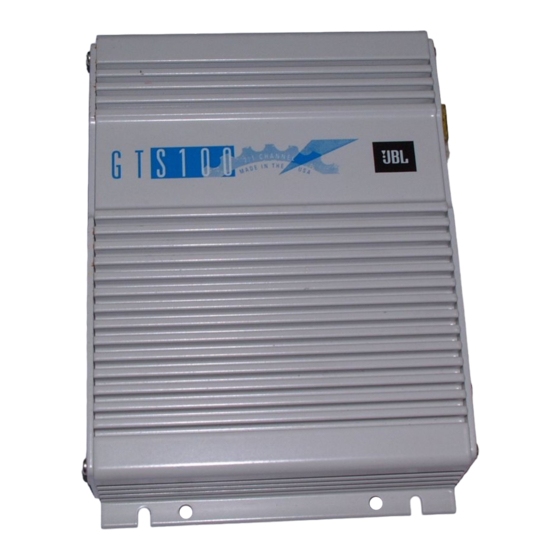
- Page 1 GTS100 2/1 CHANNEL AUTOMOTIVE POWER AMPLIFIER OWNER’S MANUAL...
-
Page 2: Table Of Contents
Table Of Contents Introduction ...3 Features...4 About Installation ...4 Quick Start ...5 System Design Using the GTS100 ...6 Typical Applications ...7 Installation Precautions...9 Physical Installation ...9 Controls and Connectors ...10 Mounting Instructions...12 Wiring...12 Power Supply Connections...14 Audio Input Connections...15 Speaker Connections ...17 Operation ...20... -
Page 3: Introduction
In addition to conventional preamp-level inputs, this model features JBL’s Universal Interface design, which facili- tates simple connection to factory radios with the low distortion that is usu- ally only associated with preamp level connection. -
Page 4: Features
JBL dealer. If the GTS100 is installed by a qualified JBL dealer, we will double the length of your warranty to two years from date of purchase . -
Page 5: Quick Start
Quick Start Recommended for experienced professional installers only! 1. Disconnect the negative cable from the battery. Note: If the vehicle’s radio features a code type security system, make certain you know the code before disconnecting the battery! 2. Mount the amplifier to the desired location using four screws. -
Page 6: System Design Using The Gts100
System Design Using the GTS100 Speakers When used in the non-bridged mode, the GTS100 can easily drive 2 ohm speaker loads. When only one speaker is connected to each channel, virtually any common speaker may be used. When two speakers are connected in... -
Page 7: Typical Applications
The following diagrams show the most common basic system configurations using the GTS100. More elaborate systems are formed by using a combination of these “building blocks.” For additional ideas, refer to the “Add On and Upgrade Section” near the end of this manual. - Page 8 Amp Crossover Input Mode Line Switch Switch High Stereo L + R Stereo Subwoofers may be used by configuring GTS100-B as shown in Application #1 or by using dual GTS100s as shown in Application #2 Line For Dual-Amplifier Switch Full-Range or Subwoofer Use...
-
Page 9: Installation Precautions
Physical Installation There are several factors to consider when selecting a mounting location for the GTS100. • It must be solidly mounted in a place where it will not be subjected to excessive shock and vibration. • Under no circumstances should the amplifier be mounted where it will be exposed to moisture or extreme heat. -
Page 10: Controls And Connectors
• The GTS100 must be mounted in a place where air can circulate around the fins on the chassis. Good air circulation around the amplifier will make it operate at lower tempera- tures and reduce the chance of the thermal protection circuits being trig- gered. - Page 11 LINE Line Level RCA Inputs Line Selector Gain Control Input Mode Speaker Input Connector Crossover Mode Selector 6. Crossover Mode Selector – This switch controls the built in crossover. Set the switch to “Off” for full band operation. Set this switch to “Low” to activate the 80Hz low pass filter on the amplifier (for subwoofer use).
-
Page 12: Mounting Instructions
Tighten the screws evenly until the unit is solidly mounted. Wiring Proper wiring of the GTS100 and the associated components is extremely important for proper performance and long term reliability. Using the proper type of wire is very important. If a spe- cific type of wire should be used for a certain application, it will be noted. -
Page 13: Typical System Configuration
Typical System Configuration Cassette/CD Tuner (Head Unit) Antenna Input Power Cassette/Receiver Antenna Power Supply Wires Power Antenna Relay Ignition Switch – Vehicle Battery Chassis Ground Cassette/CD Tuner Speaker Level Output Connection (Use only when line level ouput is not available) CD Input Cassette/CD Preamp Output S 1 0 0... -
Page 14: Power Supply Connections
Please do not call JBL for this, we stock only the pre-made harness as supplied with the amplifier. +12V Battery Wire (Yellow) •... -
Page 15: Audio Input Connections
The remote power control system turns the GTS100 off when not in use to pre- vent discharging of the vehicle’s bat- tery. When +12 volts is applied to the remote wire the amplifier is turned on. - Page 16 In the “L+R” position, the signal from both channels is summed internally. When using a sin- gle GTS100 for mono mode fed with a stereo signal it is best to use the “L+R” mode. When using a GTS100 for each...
-
Page 17: Speaker Connections
GTS100. You may simultaneously con- nect a CD player equipped with preamp volume control to the preamp-level inputs of the GTS100. The Universal Interface circuitry of the GTS100 will isolate the inputs from each other while mixing both signals. Therefore switch-... - Page 18 Please do not call JBL for this part; we stock only the harness assemblies as supplied with the amplifier. To get proper bass response and stereo imaging, all the speakers in the system must be “in phase.” The inputs terminals of the speakers will be marked in some way to identify positive and negative polarity.
- Page 19 Simultaneous Stereo-Mono Connection Diagrams A. Satellite/Subwoofer Component Values for 4 Ohm Loudspeakers* High Pass Satellite Crossover Frequency: 100Hz C: 300 F Capacitor 100V, Non-Polorized Subwoofer Low Pass Crossover Frequency: 100Hz 6.2mH Air Core Inductor LINE *You may scale the 100Hz values listed to a different desired frequency by using the following formulas: High-Pass: Low-Pass: B.
-
Page 20: Operation
If this setting does not provide adequate volume lev- els, gradually increase (turn clockwise) the gain control of the GTS100 until the system plays as loud as necessary or when the first signs of distortion are heard. -
Page 21: Solving Noise Problems
Fuse Replacement – If the fuse on the GTS100 must be replaced, DO NOT use a fuse rated for higher current lev- els. The fuse size for the GTS100 is 20 amps. Exceeding the standard fuse size or bypassing the fuse holder will void the warranty and may cause serious damage. - Page 22 If so, consult the manufacturer of the source unit, or your JBL dealer, for help in elim- inating this noise. If there is no noise in this signal, it can be eliminated as the source of the noise in your system.
- Page 23 Commercial antenna ground-loop isolators are also available. Switching Noise – The GTS100 has a highly developed switching power sup- ply which generates some RF interfer-...
-
Page 24: Maintenance
Maintenance The GTS100 does not require any regu- lar maintenance. Periodically checking the main power supply and grounding points and terminal connections is advisable. - Page 25 (see System 2). System 2A Add a Subwoofer (Active) Use the GTS100 to drive 1 or 2 subwoofers with the head unit powering the main speakers. This is an excellent way to upgrade a good stock system.
- Page 26 System 3 Add a Second GTS100 Get more power and system control by adding a second GTS100 to power the main speakers and subwoofers individually. Use the built-in crossover to high-pass the front speakers and low-pass the subwoofers. Next Step: Add power to the Rear Full- Range Speakers.
-
Page 27: In Case Of Difficulty
• Remote-on wire between the head unit and the GTS100 is disconnected or defective; check for +12 volts between the GTS100 remote on wire and the ground wire with the head unit on. • Head unit connected to speaker-level input is not BTL high-power type and no remote wire is connected;... - Page 28 Alternator whine through the audio system with the engine running. Bass output from speakers too low. If you want to talk to us about any problems, call JBL Customer Service at 1-800-336-4JBL Between 9AM and 5PM Eastern time. • Incorrect gain adjustment; verify that the GTS100 gain controls are not turned completely down.
-
Page 29: Specifications
Specifications Continuous Power Output (20Hz – 20kHz, 14.4V Battery Voltage) Signal to Noise Ratio Frequency Response Damping Factor Slew Factor Line Level Input Sensitivity (for rated power) Line Level Input Impedance Speaker Level Input Impedance Speaker Level Input Sensitivity Preamp Output Sensitivity Minimum Speaker Impedance Single Ended, Non-Bridged Bridged... - Page 30 JBL Consumer Products, Inc. 80 Crossways Park West Woodbury, NY 11797 8500 Balboa Blvd. Northridge, CA 91329 800 336 4JBL A Harman International Company Part No. JBLGTS100OM...
Need help?
Do you have a question about the GTS100 and is the answer not in the manual?
Questions and answers