
Subscribe to Our Youtube Channel
Related Manuals for StorCase Technology Data Express Ultra320 DE200


Summary of Contents for StorCase Technology Data Express Ultra320 DE200
- Page 1 ® StorCase Technology ® Data Express Ultra320 DE200 Removable SCSI Wide Ultra320 Drive Enclosure User's Guide...
- Page 2 Removable SCSI Wide Ultra320 Drive Enclosure User's Guide Part No. P89-0000-0311 A01 August 2006 StorCase Technology, Inc. 17600 Newhope Street Fountain Valley, CA 92708-9885 Phone (714) 438-1850 Fax (714) 438-1847 Ultra320 DE200 User's Guide - Rev. A01 StorCase Technology, Inc.
-
Page 3: Limited Warranty
LIMITED WARRANTY STORCASE TECHNOLOGY, Incorporated (“StorCase”) warrants that its products will be free from defects in material and workmanship, subject to the conditions and limitations set forth below. StorCase will, at its option, either repair or replace any part of its product that proves defective by reason of improper workmanship or materials. - Page 4 StorCase product, even if StorCase has been advised of the possibility of such damages. Copyright © 2006 StorCase Technology. All rights reserved. All registered trademarks are the property of StorCase Technology. All other logos and trademarks are properties of their respective companies. Ultra320 DE200 User's Guide - Rev. A01...
-
Page 5: Declaration Of Conformity
17600 Newhope Street Corporate Office Address: Fountain Valley, CA 92708 17600 Newhope Street Manufacturing Address: Fountain Valley, CA 92708 Data Express Ultra320 DE200 Product Name: S20A177, S20A178 Model Number: Conforms to the following standards: ITE Emission - EN 55022: 1998... -
Page 6: Table Of Contents
Appendix C - Attaching the ON/OFF Key to Non-Solenoid Units ......19 Appendix D - Optional Accessories ................20 Carrying Case ....................20 Drive Cover ......................21 Drive Plug ......................22 Reader's Comments ....................... 23 Ultra320 DE200 User's Guide - Rev. A01 StorCase Technology, Inc. - Page 7 Please check the StorCase web site at http://www.storcase.com or contact your StorCase representative for the latest revision of this document. StorCase Technology, Inc. Ultra320 DE200 User's Guide - Rev. A01...
-
Page 8: Ntroduction
INTRODUCTION Packaging Information ® The StorCase Technology Data Express system is shipped in a container designed to provide protection and prevent damage during shipment. The Data Express unit was carefully in- spected before and during the packing procedure at the factory. Bent or broken connectors, or evidence of other damage to the Data Express should be reported to the shipper immediately. -
Page 9: Package Contents
0430k Alignment Tool 5. Insert Sheet Drive Lock Keys 6. #6-32 Phillips Machine Hd. Receiving Frame Mounting Screws Drive Carrier 7. #6-32 Phillips F.H. Mounting Screws Figure 1: Package Contents StorCase Technology, Inc. Ultra320 DE200 User's Guide - Rev. A01... -
Page 10: General Description
Ultra320 DE200 receiving frames are indicated by their BLUE LED, while the Ultra320 DE200 carriers are indicated by the Ultra320 logo. ® The StorCase Technology Data Express Ultra320 DE200 is composed of a receiving frame which supports SCSI Ultra320 interfaces and fits within a 5.25" half-height peripheral slot (Figure 2). -
Page 11: Receiving Frame Front Panel
All Steel Receiving Frame Device Spin Down/Up Timer Switch BLUE Unit ID Number Indicator Receiving Frame BLUE Activity Front Indicator 0231C Key Lock/Drive Power Switch Figure 3: Receiving Frame Front Panel StorCase Technology, Inc. Ultra320 DE200 User's Guide - Rev. A01... -
Page 12: Receiving Frame Rear Panel
Factory-Installed Jumpers: There are three (3) jumpers factory-installed on W1. These jumpers are located on Pins 9 & 10, 19 & 20, and Pins 21 & 22. NOTE: Do not remove these jumpers! Ultra320 DE200 User's Guide - Rev. A01 StorCase Technology, Inc. -
Page 13: Figure 5: Receiving Frame (Rear View)
(Factory-Installed on Pins 7 & 8 and Pins 9 & 10 J4 Jumper Do Not Remove!) (Factory-Installed Do Not Remove!) Factory-Installed Jumpers (Do Not Remove!) Figure 5: Receiving Frame (Rear View) StorCase Technology, Inc. Ultra320 DE200 User's Guide - Rev. A01... -
Page 14: Installation
ID Select Jumpers: Locate the ID select jumper positions on the drive, and remove any jumper plugs in this area (the drive carrier board will plug into this section of the drive). Ultra320 DE200 User's Guide - Rev. A01 StorCase Technology, Inc. -
Page 15: Figure 6: Drive Installation Assembly
Fasten the drive into place with four (4) #6-32 Phillips Flat Hd. screws (Figure 6). Drive (Not Included) Drive Carrier Board Drive Carrier 0151g #6-32 x 1/4 Phillips Flat Head Screw (4 each) Figure 6: Drive Installation Assembly StorCase Technology, Inc. Ultra320 DE200 User's Guide - Rev. A01... -
Page 16: Installing The Receiving Frame
SCSI ID Ground Reserved Reserved SYNC Drive Synchronous Signal Ground RMST Remote Start (see Table 2) Ground DYST Delay Start (see Table 2) Ground Reserved Reserved Reserved Reserved Reserved Reserved Ultra320 DE200 User's Guide - Rev. A01 StorCase Technology, Inc. -
Page 17: Figure 7: Receiving Frame Motherboard Option Pins
Use the mounting holes which best suit the com- puter or expansion chassis configuration. 0496a Figure 8: Receiving Frame Mounting Holes StorCase Technology, Inc. Ultra320 DE200 User's Guide - Rev. A01... -
Page 18: Table 2: Option Pins 13-16 Drive Motor Control
Adjust the front of the receiving frame so the carrier slides freely in and out on the receiving frame guides. The position of adjoining peripheral units may require ad- justment. Ultra320 DE200 User's Guide - Rev. A01 StorCase Technology, Inc. -
Page 19: Selecting The Unit Id Number
Unlock the DE200 drive carrier and remove it from the receiving frame. A "u" will be displayed initially when the unit is unlocked but will return to a number when the carrier is removed from the receiving frame. StorCase Technology, Inc. Ultra320 DE200 User's Guide - Rev. A01... -
Page 20: Figure 9: Unit Id Select Switch Location
Refer to the drive and/or computer manufacturer's documentation for formatting information. Unit ID Number Display ID Select Rotating Switch 0179i Figure 9: Unit ID Select Switch Location Ultra320 DE200 User's Guide - Rev. A01 StorCase Technology, Inc. -
Page 21: Adjusting The Spin Down/Up Timer
D = 75 SECONDS 6 = 40 SECONDS E = 80 SECONDS 7 = 45 SECONDS F = 85 SECONDS Front of 0143 Receiving Frame Figure 10: Device Spin Down/Up Timer Switch StorCase Technology, Inc. Ultra320 DE200 User's Guide - Rev. A01... -
Page 22: Appendices
Appendix A - Specifications/Dimensions APPENDICES Ultra320 DE200 User's Guide - Rev. A01 StorCase Technology, Inc. -
Page 23: Appendix A - Specifications/Dimensions
7.38" (187.5mm) 8.18" (207.8mm) Weight 1.2lb (0.55kg) 1.3lb (0.59kg) (1)) With carrier removed. Chassis Reliability/Maintainability MTBF 500,000 Hours MTTR 5 Minutes Preventive Maintenance None Electrical Specifications Input 34mA +12V 660µA StorCase Technology, Inc. Ultra320 DE200 User's Guide - Rev. A01... -
Page 24: Figure A-1: Ultra320 De200 Physical Dimensions
Appendix A - Specifications/Dimensions Isolator Board DE200 8.19 (208.0mm) Board 373c Figure A-1: Ultra320 DE200 Physical Dimensions (Dimensions are for reference only) Ultra320 DE200 User's Guide - Rev. A01 StorCase Technology, Inc. -
Page 25: Appendix B - Factory-Installed Options
The solenoid option provides an extra step in drive protection by preventing the removal and movement of the drive until the drive motor has fully stopped. Figure B-1: Solenoid Mechanism StorCase Technology, Inc. Ultra320 DE200 User's Guide - Rev. A01... -
Page 26: Appendix C - Attaching The On/Off Key To Non-Solenoid Units
4. Rotate the key 180 degrees clockwise. 5. Reinstall the pawl into the access hole with the alignment tool. The key is now attached to the key lock mecha- nism. Figure C-1: Attaching the ON/OFF Key Ultra320 DE200 User's Guide - Rev. A01 StorCase Technology, Inc. -
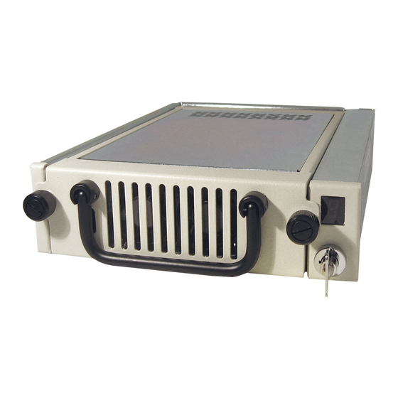
Page 27: Appendix D - Optional Accessories
7” long x 9” wide x 4” high, make it easy to carry and to store. The foam lining is contoured to fit a single Data Express carrier. Contact your StorCase dealer for further details and ordering information. StorCase Technology, Inc. Ultra320 DE200 User's Guide - Rev. A01... -
Page 28: Drive Cover
DE200, except the full drive cover protects the drive as well as the cables. It is easily installed with two (2) #6-32 Phillips Flat Hd. screws as shown in the illustration above. Ultra320 DE200 User's Guide - Rev. A01 StorCase Technology, Inc. -
Page 29: Drive Plug
The purpose of the plug is to provide an attractive and functional method of directing proper air flow to the other installed devices in the system or external enclosure. StorCase Technology, Inc. Ultra320 DE200 User's Guide - Rev. A01... -
Page 30: Reader's Comments
Are there any changes you would like us to make, either with the hardware itself, or with the installation instructions? Everyone at StorCase Technology is working toward the goal of providing you with the highest quality, most cost effective, products available on the market, and we need your comments to guide our efforts. - Page 31 B U S I N E S S R E P LY M A I L FIRST CLASS MAIL PERMIT NO. 10686 SANTA ANA, CA POSTAGE WILL BE PAID BY ADDRESSEE TECHNOLOGY CORPORATION 17600 NEWHOPE STREET FOUNTAIN VALLEY CA 92708-9885 StorCase Technology, Inc. Ultra320 DE200 User's Guide - Rev. A01...
Need help?
Do you have a question about the Data Express Ultra320 DE200 and is the answer not in the manual?
Questions and answers