
Related Manuals for StorCase Technology DataExpress DE75i-A100


Summary of Contents for StorCase Technology DataExpress DE75i-A100
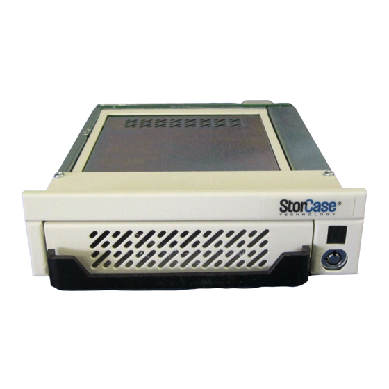
- Page 1 StorCase Technology ® Data Express ® DE75i-A100 Removable Ultra ATA133 Low-Profile Drive Enclosure User's Guide...
- Page 2 StorCase Technology ® Data Express ® DE75i-A100 Removable Ultra ATA133 Low-Profile Drive Enclosure User's Guide Part No. D89-0000-0110 D02 October 2005...
- Page 3 LIMITED WARRANTY...
-
Page 5: Declaration Of Conformity
Declaration of Conformity... - Page 6 Table of Contents...
- Page 7 List of Figures List of Tables...
- Page 8 INTRODUCTION Packaging Information ® Serial Numbers Receiving Frame: Drive Carrier:...
-
Page 9: Package Contents
Package Contents 0601b... -
Page 10: General Description
General Description ®... - Page 11 Receiving Frame Front Panel...
-
Page 12: Receiving Frame Rear Panel
Receiving Frame Rear Panel DC Power I/O Connector Connector Master/Slave Configuration Jumper (Do Not Remove!) 0603a = Pin 1 Cathode Anode JP4 Option Remote Activity... -
Page 13: Installation
INSTALLATION Installing the Drive into the Carrier Preparation Master/Slave Drive Selection Method 1... - Page 14 Method 2 I/O Connector (J2) = Pin 1...
- Page 15 ATA66/100 Drive Jumper Installed Pin 3 Pin 2 Seagate ATA66/100 Drive Pin 3 Pin 2 Western Digital ATA66 Drive Pin 3 Pin 2 Pin 3 Pin 2 Western Digital ATA100 Drive Maxtor ATA66 Drive Pin 3 Pin 2 Pin 3 Pin 2 Maxtor ATA100 Drive...
- Page 16 Single (1) Western Digital ATA100 Drive: = Jumper Installed Dual (2) Western Digital ATA100 Drives: Master Slave Other Drives: Master Slave (or Single) 112b...
- Page 17 Installation Protective Drive Cover (Provided) Drive (Not Included) Power Cable I/O Cable Fabricated Cable (Used for Master/Slave Drive Connection, not included. See “Installation” section for further Drive Carrier Drive Cover Screws (2 plcs) Drive Mounting # 6-32 x 3/16 Screws (4ea) Flat HD Phillips # 6-32 x 3/16 Flat HD...
-
Page 18: Installing The Receiving Frame
Installing the Receiving Frame... - Page 20 Selecting the Unit ID Number...
-
Page 21: Unit Id Select Switch Settings
Unit ID Select Switch Settings Unit ID Select Position Drive Master Slave Master Slave Selection Unit ID Number Blank Blank Blank Blank Blank Blank Display 824b... - Page 22 AT/IDE Interface Connector JP1 - Indicates an active-low signal. Signal direction is with respect to the host. "I" indicates To the host "O" indicates From the host The PDIAG and DASP signals are used for communication between master and slave.
- Page 23 This Page Left Blank Intentionally.
- Page 24 APPENDICES...
-
Page 25: Appendix A - Specifications/Dimensions
Appendix A - Specifications/Dimensions... -
Page 27: Appendix B - Attaching The On/Off Key
Appendix B - Attaching the ON/OFF Key... -
Page 28: Appendix C - Optional Accessories
Appendix C - Optional Accessories Carrying Case 320FW_13... - Page 29 This Page Left Blank Intentionally.
-
Page 30: Reader's Comments
Reader's Comments... - Page 31 FOLD ALONG THIS LINE AND STAPLE SHUT NO POSTAGE NECESSARY IF MAILED IN THE UNITED STATES B U S I N E S S R E P LY M A I L FIRST CLASS MAIL PERMIT NO. 10686 SANTA ANA, CA POSTAGE WILL BE PAID BY ADDRESSEE TECHNOLOGY CORPORATION 17600 NEWHOPE STREET...
Need help?
Do you have a question about the DataExpress DE75i-A100 and is the answer not in the manual?
Questions and answers