LG-Nortel ARIA SOHO Installation Manual
Hardware description and installation manual
Hide thumbs
Also See for ARIA SOHO:
- Feature description and operation manual (271 pages) ,
- Hardware description and installation manual (67 pages) ,
- Quick start manual (38 pages)
Table of Contents
Advertisement
Advertisement
Table of Contents

Related Manuals for LG-Nortel ARIA SOHO

Summary of Contents for LG-Nortel ARIA SOHO
- Page 1 ARIA SOHO Hardware Description and Installation Manual...
-
Page 2: Regulatory Information
The local telephone company may make changes in its communications facilities or procedures. If these changes could reasonably be expected to affect the use of the ARIA SOHO or compatibility with the network, the telephone company is required to give advanced written notice to the user, allowing the user to take appropriate steps to maintain telephone service. - Page 3 ARIA SOHO Hardware Description and Installation Manual Issue 1 Mar, 2007 Revision History ISSUE DATE CONTENTS OF CHANGES REMARK ISSUE 1.0 2007.03 Initial Release...
-
Page 4: Table Of Contents
ARIA SOHO Hardware Description and Installation Manual Issue 1 Mar, 2007 Table of Contents 1 INTRODUCTION ....................1 1.1 Important Safety Instructions ..................1 1.1.1 Safety Requirements ........................ 1 1.2 Precaution ........................2 1.2.1 Caution ........................... 2 1.2.2 Disposal of Old Appliance......................2 1.3 Manual Usage ........................ - Page 5 5.2.1 Wall Mount Wiring........................42 5.2.2 Rack Mount Wiring........................43 6 STARTING THE ARIA SOHO ................44 6.1 Before Starting the ARIA SOHO System ..............44 6.2 Basic Programming ......................45 6.2.1 DKT Programming ........................45 6.2.2 Entering the Programming Mode.................... 46 6.2.3 Pre-Programming........................
-
Page 6: Introduction
ARIA SOHO Hardware Description and Installation Manual Issue 1 INTRODUCTION Mar, 2007 1.1 Important Safety Instructions 1.1.1 Safety Requirements When using your telephone equipment, basic safety precautions should always be followed to reduce the risk of fire, electric shock and other personal injury, including the following: Please read and understand all instructions. -
Page 7: Precaution
Never attempt to insert wires, pins, etc. into the system. If the system does not operate properly, the equipment should be repaired by an authorized LG-Nortel service center. Do not use benzene, paint thinner, or an abrasive powder to clean the KSU. Wipe it with a soft cloth only. -
Page 8: Manual Usage
Provides general information on the ARIA SOHO System, including the system specifications and capacity. Section 3. KSU Installation Describes detailed instructions for planning the installation site and procedures to install the ARIA SOHO System. Section 4. Board Installation Describes detailed instructions for installing components of the ARIA SOHO Board. -
Page 9: The List Of Abbreviations
ARIA SOHO Hardware Description and Installation Manual Issue 1 INTRODUCTION Mar, 2007 1.4 The list of abbreviations AAFU: Auto Attendant Function Unit AC: Alternating Current ACD: Automatic Call Distributor ADPCM: Adaptive Differential Pulse Code Modulation AWG: American Wire Gauge CHB308: 3 CO lines and 8 hybrid interface board... -
Page 10: System Overview
- Basic CID (CO & SLT) Function - Basic USB port - 8 Poly internal MOH (13 Music sources) 2.1.1 System Connection Diagram The following Figure shows the components that make up the ARIA SOHO System: FIGURE 2.1.1 SYSTEM CONNECTION DIAGRAM... -
Page 11: System Components
ARIA SOHO Hardware Description and Installation Manual Issue 1 SYSTEM OVERVIEW Mar, 2007 2.2 System Components BASIC KSU ITEM OPTION BOARD DESCRIPTION Key Service Unit Power Supply Unit Main Board Unit (3CO, 8DKT/1DKT and 7SLT) Main Board CO and Extension Boards... -
Page 12: Specifications
ARIA SOHO Hardware Description and Installation Manual Issue 1 SYSTEM OVERVIEW Mar, 2007 2.3 Specifications 2.3.1 General Specifications ITEM DESCRIPTION SPECIFICATION ARM7 TDMI core(32bit, 50MHz) Custom Mixed-Signal ASIC Device Switching Device 7years Memory Back-up Duration AC Voltage Input 230 +/- 10% Volt AC @47-63Hz... -
Page 13: System Capacity
ARIA SOHO Hardware Description and Installation Manual Issue 1 SYSTEM OVERVIEW Mar, 2007 2.3.2 System Capacity DESCRIPTION CAPACITY/BOARD TOTAL Time Slots 3/MBU, 3/CHB308, 3/CSB316 Max. 6 CO Line Ports 8/MBU, 8/CHB308, 16/CSB316 Max. 24 Max Direct Station (DKT, SLT, DSS) Connections 2/DPU2 Max. -
Page 14: Ksu Installation
Anti-static precautions should be taken during installation. 3.1.2 Installation precautions The ARIA SOHO System is designed for wall mounting or a free –standing rack. Avoid installing in the following places: In direct sunlight and hot, cold, or humid places. Temperature range = 0 to 40 Places where shocks or vibrations are frequent or strong. -
Page 15: Ksu Installation
ARIA SOHO Hardware Description and Installation Manual Issue 1 KSU INSTALLATION Mar, 2007 3.2 KSU Installation 3.2.1 Unpacking Open the box and verify that the items shown in Figure 3.2.1 are included: Key service unit Mounting template Quick Start Guide... -
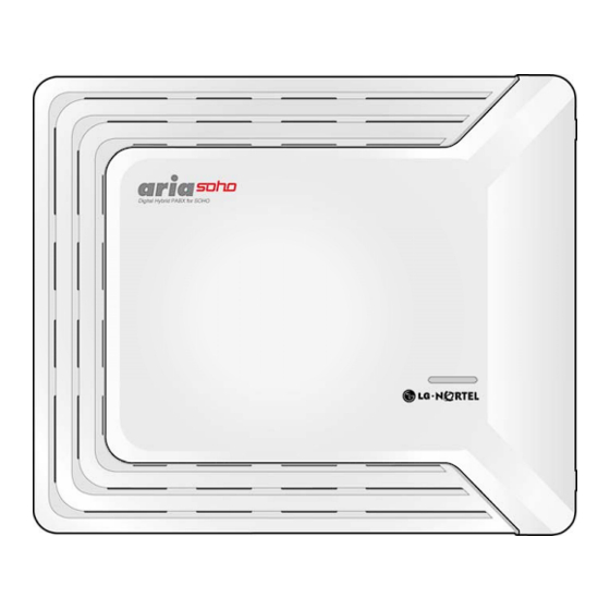
Page 16: Ksu Exterior And Dimension
ARIA SOHO Hardware Description and Installation Manual Issue 1 KSU INSTALLATION Mar, 2007 3.2.2 KSU Exterior and Dimension Figure 3.2.2 shows the exterior and dimensions of the KSU. Figure 3.2.2 KSU Exterior and Dimension... -
Page 17: Opening And Closing The
ARIA SOHO Hardware Description and Installation Manual Issue 1 KSU INSTALLATION Mar, 2007 3.2.3 Opening and Closing the Front Cover 3.2.3.1 Opening the Front Cover 1. Open the Cord cover and turn the screws counter-clockwise to loosen as shown in Figure 3.2.3.1. - Page 18 3. Turn the screws clockwise to tighten and close the Cord Cover as in the Figure. FIGURE 3.2.3.2 CLOSING THE FRONT COVER ㅡ NOTE Prior to operation, the front cover of the ARIA SOHO must be closed and the screws tightened.
-
Page 19: Power Supply Unit Installation
ARIA SOHO Hardware Description and Installation Manual Issue 1 KSU INSTALLATION Mar, 2007 3.2.4 Power Supply Unit Installation The Power Supply Unit (PSU) is installed in the KSU by the manufacturer prior to shipping. Before installation, make sure that the KSU is not plugged into an outlet. The PSU is located at the rear-most area of the KSU and is capable of providing four kinds of power sources to the MBU through the 7-pin connector, CN7 (refer to the following Table). -
Page 20: Frame Ground Connection
UL 1015 AWG#18 (1.0mm)). It is recommended that the ground wire is shorter than 1m (3.28ft). We do not provide the ground wire. Proper grounding is very important to protect the ARIA SOHO from external noise and to reduce the risk of electrocution in the event of lightning strike. -
Page 21: External Backup Battery Installation
Mar, 2007 3.2.6 External Backup Battery Installation In case of power failure, the external backup batteries automatically maintain uninterrupted power for the ARIA SOHO System. The external batteries must provide 24V DC; this is generally accomplished by connecting two 12V batteries in a series arrangement as shown: FIGURE 3.2.6 EXTERNAL BACKUP BATTERY INSTALLATION... -
Page 22: Ksu Mounting
ARIA SOHO Hardware Description and Installation Manual Issue 1 KSU INSTALLATION Mar, 2007 3.2.7 KSU Mounting 3.2.7.1 Wall Mounting 1. Install 3 anchor plugs in the wall using the mounting template included for accurate placement (Figure 3.2.7.1A). 2. Attach the mounting template using the 3 screws and anchors included. - Page 23 ARIA SOHO Hardware Description and Installation Manual Issue 1 KSU INSTALLATION Mar, 2007 FIGURE 3.2.7.1B KSU WALL MOUNTING ㅡ NOTE Be careful not to drop the KSU.
- Page 24 1. Affix the bracket with the 4 screws provided (Figure 3.2.7.2A). FIGURE 3.2.7.2A RACK MOUNTING 2. Attach the rack bracket to the bottom of the ARIA SOHO System as shown in Figure 3.2.7.2B, and attach it to the System securely by tightening the screws clockwise.
-
Page 25: Board Installation
ARIA SOHO Hardware Description and Installation Manual Issue 1 BOARD INSTALLATION Mar, 2007 4.1 Installation of the Boards Prior to installing the Boards, the following should be considered: CAUTION Power must be turned OFF. To protect the System from static electricity, do not touch the boards. To discharge static, touch a grounded object, or wear a grounding strap. -
Page 26: Main Board Unit (Mbu)
ARIA SOHO Hardware Description and Installation Manual Issue 1 BOARD INSTALLATION Mar, 2007 4.2 Main Board Unit (MBU) The Main Board Unit (MBU) controls communication between the peripheral interfaces, supervises all resources in the system, controls the gain adjustment of the PCM signal, generates the System tones, and manages System call processing. - Page 27 ARIA SOHO Hardware Description and Installation Manual Issue 1 BOARD INSTALLATION Mar, 2007 FIGURE 4.2B MBU CONNECTION PORTS CONNECTOR, MODULAR JACK AND SWITCH FUNCTIONS SWITCH/CONNECTOR FUNCTIONS REMARK KSU Connection 50Pins CO and Extension Board(CHB308/CSB316/SLIB8) installation 50Pins LANU Installation 32Pins MODU Installation...
-
Page 28: Modular Jack (Mj1 - Mj3) Pin Assignment
ARIA SOHO Hardware Description and Installation Manual Issue 1 BOARD INSTALLATION Mar, 2007 4.2.1 Modular Jack (MJ1 – MJ3) Pin Assignment 4.2.1.1 MBU MJ1 (CO) MBU MJ1–1,2,3 Connector PIN Number Signal Name RJ11 CO-T, CO-R 4.2.1.2 MBU MJ2 (Extension) MBU MJ2-1 (DKT ONLY) -
Page 29: Switch, Led And Connector
ARIA SOHO Hardware Description and Installation Manual Issue 1 BOARD INSTALLATION Mar, 2007 4.2.1.3 MJ3 Pin Assignment (Alarm Detection and Relay Contact) CONNECTOR PIN NUMBER SIGNAL NAME RJ11 ALARM-T ALARM-R Relay-T Relay-R MJ4 PIN ASSIGNMENT (USB) CONNECTOR PIN NUMBER SIGNAL NAME... - Page 30 ARIA SOHO Hardware Description and Installation Manual Issue 1 BOARD INSTALLATION Mar, 2007 4.2.2.2 CN8 Pin Assignment CONNECTOR PIN NUMBER SIGNAL NAME FUNCTION RS-232C Reserved Transmitted Data Received Data Not Used Signal Ground Not Used Not Used Not Used Reserved...
-
Page 31: Installation Of The Co Line & Extension Board
ARIA SOHO Hardware Description and Installation Manual Issue 1 BOARD INSTALLATION Mar, 2007 4.3 Installation of the CO Line & Extension Board NOTE—These Boards(CHB308/CSB316/SLIB8) are not available in AR-CKSU[Compact KSU] CONNECTOR BOARD LINE DESCRIPTION CABLE REMARK TYPE 3 CO Line and 8 Hybrid... - Page 32 ARIA SOHO Hardware Description and Installation Manual Issue 1 BOARD INSTALLATION Mar, 2007 4.3.1.1 Modular Jack (MJ1-MJ2) Pin Assignment CHB308 MJ1 – 1,2,3 CONNECTOR PIN NUMBER SIGNAL NAME RJ11 CO-T, CO-R CHB308 MJ2 – 1,2,3,4,5,6,7,8 (EXTENSION) CONNECTOR PIN NUMBER SIGNAL NAME...
-
Page 33: Csb316 (3 Co And 16 Slt Interface Board) [Not Available In Ar-Cksu]
ARIA SOHO Hardware Description and Installation Manual Issue 1 BOARD INSTALLATION Mar, 2007 4.3.2 CSB316 (3 CO and 16 SLT Interface Board) [not available in AR-CKSU] The CSB316 can be installed on the CHB308/CSB316/SLIB8(CN2) connector of the MBU, and provides 3 CO/PBX Loop Start CO Line interfaces that support Pulse/DTMF signaling. - Page 34 ARIA SOHO Hardware Description and Installation Manual Issue 1 BOARD INSTALLATION Mar, 2007 FIGURE 4.4.2.2 TERMINAL BLOCK TERMINAL SLT CONNECTOR PIN NUMBER SIGNAL NAME RJ11 TIP, RING CONNECTOR FUNCTIONS CONNECTOR FUNCTION REMARKS MBU Connection 50Pins CN2 and CN3 CMU50PR Connection 6 &...
- Page 35 ARIA SOHO Hardware Description and Installation Manual Issue 1 BOARD INSTALLATION Mar, 2007 4.3.2.2 Add-On Board CMU50PR (Call Metering-50Hz and Polarity Detection Unit) The CMU50PR provides 3 Call Metering Detection for 50Hz and provides 3 channels of Polarity Reversal detection for call metering.
-
Page 36: Slib8 (8 Slt Interface Board) [Not Available In Ar-Cksu]
ARIA SOHO Hardware Description and Installation Manual Issue 1 BOARD INSTALLATION Mar, 2007 4.3.3 SLIB8 (8 SLT Interface Board) [not available in AR-CKSU] The SLIB8 can be installed on the CHB308/CSB316/SLIB8(CN2) connector of the MBU, and provides 8 possible SLT interfaces. -
Page 37: Other Board Installations
ARIA SOHO Hardware Description and Installation Manual Issue 1 BOARD INSTALLATION Mar, 2007 4.4 Other Board Installations 4.4.1 Voice Mail Interface Unit (VMIU) The Voice Mail Interface Unit (VMIU) can be installed on the VMIU/AAFU connector (CN5) of the MBU, and provides the capability for System announcements, ACD/UCD announcements, and User Greetings. -
Page 38: Auto Attendant Function Unit (Aafu)
ARIA SOHO Hardware Description and Installation Manual Issue 1 BOARD INSTALLATION Mar, 2007 4.4.2 Auto Attendant Function Unit (AAFU) The Auto Attendant Function Unit (AAFU) can be installed on the VMIU/AAFU connector (CN5) of the MBU, and provides System Announcement and ACD/UCD Announcements. -
Page 39: Lan Interface Unit (Lanu)
ARIA SOHO Hardware Description and Installation Manual Issue 1 BOARD INSTALLATION Mar, 2007 4.4.3 LAN Interface Unit (LANU) LAN Interface Unit (LANU) should be installed on the LANU connector (CN3) of the MBU and provides 1 LAN port of 10 Base-T networking. RJ45 Modular Jack, MJ1 is used to interface with a Wide Area Network (WAN) or PC. Two LEDs are provided to indicate the operational state of the LAN port. -
Page 40: Modem Function Unit (Modu)
ARIA SOHO Hardware Description and Installation Manual Issue 1 BOARD INSTALLATION Mar, 2007 4.4.4 Modem Function Unit (MODU) MODU should be installed on the MODU connectors (CN4) of the MBU, and provides an analog modem connection. It supports Bell, ITU-T, V.34, V.32BIS, V.90 Protocol at a speed rate of 300bps up to 33Kbps, and automatic rate negotiation. -
Page 41: Dpu2 (Two Door Phone Unit)
ARIA SOHO Hardware Description and Installation Manual Issue 1 BOARD INSTALLATION Mar, 2007 4.4.5 DPU2 (Two Door Phone Unit) The Two Door Phone Unit (DPU2) should be installed on the DPU2 connector (CN13) of the MBU, and provides two Door Phone interfaces and two Relay contacts for door opener. -
Page 42: Cmu50Pr (Call Metering-50Hz And Polarity Reversal Detection Unit)
ARIA SOHO Hardware Description and Installation Manual Issue 1 BOARD INSTALLATION Mar, 2007 4.4.6 CMU50PR (Call Metering-50Hz and Polarity Reversal Detection Unit) The Call Metering-50Hz and Polarity Reversal Detection Unit (CMU50PR) provides 3 Call Metering Detection circuits for 50Hz and provides 3 channels of Polarity Reversal Detection for Call Metering or signaling. It can be installed on MBU, CHB308 and CSB316. -
Page 43: Terminal Connection And Wiring Method
Issue 1 TERMINAL CONNECTION AND WIRING METHOD Mar, 2007 5.1 Terminal and Door Phone Models Various types of digital terminals can be used with the ARIA SOHO MBU /CHB308 as listed in the Table and show below: MODEL DESCRIPTION LDP-7208D... -
Page 44: Terminal Cabling Distance
ARIA SOHO Hardware Description and Installation Manual Issue 1 TERMINAL CONNECTION AND WIRING METHOD Mar, 2007 5.1.1 Terminal Cabling Distance FIGURE 5.1.1 TERMINAL CABLING DISTANCE 5.1.2 Basic Terminal and DSS Connection 5.1.2.1 DKT The following illustrates how to connect the DKT to your System: FIGURE 5.1.2.1 DKT CONNECTION... - Page 45 ARIA SOHO Hardware Description and Installation Manual Issue 1 TERMINAL CONNECTION AND WIRING METHOD Mar, 2007 5.1.2.2 SLT The following illustrates how to connect the SLT to your System: FIGURE 5.1.2.2 SLT CONNECTION PIN ASSIGNMENT CONNECTOR PIN NUMBER SIGNAL NAME...
-
Page 46: Connecting Additional Terminals
ARIA SOHO Hardware Description and Installation Manual Issue 1 TERMINAL CONNECTION AND WIRING METHOD Mar, 2007 5.1.3 Connecting Additional Terminals The MBU provides connections for one external music source, one external page port, one relay contact, and an alarm detection input monitor through the PJ1 (RED, External MOH) and PJ2 (BLUE, External Page) audio jack and a MJ3 (RJ11 Modular Jack). -
Page 47: Cable Wiring
ARIA SOHO Hardware Description and Installation Manual Issue 1 TERMINAL CONNECTION AND WIRING METHOD Mar, 2007 5.2 Cable Wiring 5.2.1 Wall Mount Wiring To install wall mount wiring, perform the following Steps: 1. Ensure the BKSU have been installed correctly. -
Page 48: Rack Mount Wiring
ARIA SOHO Hardware Description and Installation Manual Issue 1 TERMINAL CONNECTION AND WIRING METHOD Mar, 2007 5.2.2 Rack Mount Wiring 1. Ensure the BKSU have been installed correctly. 2. Connect cables to the CO/STA port and the MOH/USB/RS-232C ports as shown in Figure 5.2.2. -
Page 49: Starting The Aria Soho
2. Check the DIP switch (SW1) of the MBU to All ON. 3. Plug the AC power cord into the ARIA SOHO System and AC outlet. 4. Program the Nation Code (PGM100) as applicable. 5. Reset the ARIA SOHO System. -
Page 50: Basic Programming
STARTING THE ARIA SOHO Mar, 2007 6.2 Basic Programming The ARIA SOHO System can be programmed to meet an individual customer’s needs. There are two ways to perform Admin Programming: PC Admin – Refer to PC Admin Programming Manual DKT – In this manual, DKT (Station 100) Admin Programming is described. -
Page 51: Entering The Programming Mode
ARIA SOHO Hardware Description and Installation Manual Issue 1 STARTING THE ARIA SOHO Mar, 2007 6.2.2 Entering the Programming Mode To enter programming mode, perform the following Steps: 1. Lift the Handset. 2. 1. Press the [MON] button on the Admin Station; the ICM tone should be heard. -
Page 52: Pre-Programming
1. Press the [TRANS/PGM] button + PGM number (100) then [FLEX1] + 7 [Nation Code for CIS]. 2. Press the [HOLD/SAVE] button to accept the change. 3. Now Rest ARIA SOHO to initialize Database for Nation. 4. Set the 4 pole (SW1) of the MBU OFF when the System operates normally to protect programmed features. - Page 53 ARIA SOHO Hardware Description and Installation Manual Issue 1 STARTING THE ARIA SOHO Mar, 2007 NATION CODE TABLE NATION CODE NATION CODE NATION CODE America Argentina Australia Bahrain Bangladesh Belgium Bolivia Brazil Brunei Burma Cameroon China China (Taiwan) Colombia Costa Rica...
- Page 54 ARIA SOHO Hardware Description and Installation Manual Issue 1 STARTING THE ARIA SOHO Mar, 2007 6.2.3.2 Board Assignment (PGM 101) To use CO line, extension line, and board, first of all if the code of these boards is registered on system at PGM101, you can normally use the board.
-
Page 55: Logical Slot Assignment
ARIA SOHO Hardware Description and Installation Manual Issue 1 STARTING THE ARIA SOHO Mar, 2007 6.2.3.3 Logical Slot Assignment (PGM 103) If assignment of each board is over, it is automatically registered by slot number order. User can reassign slot order of each CO Line or extension line to appropriate to user circumstance. -
Page 56: Flexible Numbering Plan
ARIA SOHO Hardware Description and Installation Manual Issue 1 STARTING THE ARIA SOHO Mar, 2007 6.2.3.5 Flexible Numbering Plan (PGM 105) To set the Flexible Numbering Plan, perform the following Steps: 1. Press the [TRANS/PGM] button + 105. 2. Enter the Station Range (dial the Start and End numbers as described in the Table). -
Page 57: System Ip Setup
ARIA SOHO Hardware Description and Installation Manual Issue 1 STARTING THE ARIA SOHO Mar, 2007 FLEX ITEM DEFAULT VALUE MSG Wait/Call Back Answer Speed Dial Access Cancel DND/CFW/Pre-Selected MSG Features SLT Hold Reserved Reserved SLT Program Mode Select ACD Reroute To program Flexible numbering using PGM 107, perform the following Steps: 1. - Page 58 ARIA SOHO Hardware Description and Installation Manual Issue 1 STARTING THE ARIA SOHO Mar, 2007 Server IP Address 1. Press the [TRANS/PGM] button + 108. 2. Press the [FLEX2] Button. 3. Enter the server IP Address (12 digits). (ex., 192168131154 for IP : 192.168.131.154 ) 4.
-
Page 59: Troubleshooting
ARIA SOHO Hardware Description and Installation Manual Issue 1 TROUBLESHOOTING Mar, 2007 PROBLEM CAUSE/SYMPTOM SOLUTION Exchange the malfunctioning board for Power short circuit some one in good working condition. board(s) Dust each board with a dry cloth. SYSTEM POWER FAILURE Check the PSU fuse.