Sun Microsystems Sun Fire X4140 Service Manual
Hide thumbs
Also See for Sun Fire X4140:
- Diagnostics manual (80 pages) ,
- Safety and compliance manual (22 pages)
Table of Contents
Advertisement
Quick Links
Download this manual
See also:
Diagnostic Manual
Advertisement
Table of Contents

Related Manuals for Sun Microsystems Sun Fire X4140


Summary of Contents for Sun Microsystems Sun Fire X4140
- Page 1 Sun Fire™ X4140 Server Service Manual Part No. 820-2401-14 September 2010, Revision A...
- Page 2 Cette distribution peut inclure des éléments développés par des tiers . Sun, Sun Microsystems, le logo Sun, Java, Solaris et Sun Fire 4140, Sun Fire 4240, and Sun Fire 4440 sont des marques de fabrique ou des marques déposées de Sun Microsystems, Inc., ou ses filiales, aux Etats-Unis et dans d'autres pays.
-
Page 3: Table Of Contents
Infrastructure Boards 1–4 1.2.2 Dimensions 1–5 1.2.3 System Cables 1–5 Sun Fire X4140 Server Front Panel Features 1–8 Sun Fire X4140 Server Rear Panel Features 1–9 Illustrated Parts Breakdown 1–10 Preparing to Service the System 2–1 Safety Information 2–1 Required Tools 2–2 Obtaining the Chassis Serial Number 2–2... - Page 4 Fan Module LED Reference 3–10 3.3.3 Detecting Fan Module Failure 3–11 3.3.4 Removing a Fan Module 3–11 3.3.5 Installing a Fan Module 3–12 Servicing Power Supplies 3–14 3.4.1 Detecting Power Supply Failure 3–14 Sun Fire X4140 Server Service Manual • September 2010...
- Page 5 4.3.1 Removing a PCIe Riser 4–13 4.3.2 Installing a PCIe Riser 4–14 Servicing PCIe Cards 4–15 4.4.1 Sun Fire X4140 Server PCIe Card Guidelines 4–16 4.4.1.1 Riser Cards 4–16 4.4.1.2 Guidelines for SGXPCIESAS-R-INT-Z HBA Card 4–16 4.4.2 Removing PCIe Cards 4–17 4.4.3...
- Page 6 Servicing Infrastructure Boards and Components 5–1 Servicing the DVD/USB Module 5–2 5.1.1 Removing the DVD/USB Module 5–2 5.1.2 Installing the DVD/USB Module 5–3 Servicing the Fan Power Boards 5–4 5.2.1 Removing a Fan Power Board 5–5 Sun Fire X4140 Server Service Manual • September 2010...
- Page 7 5.2.2 Installing a Fan Power Board 5–6 Servicing the Drives Cage 5–7 5.3.1 Removing the Drives Cage 5–7 5.3.2 Installing the Drives Cage 5–9 Servicing the Drives Backplane 5–11 5.4.1 Removing the Drives Backplane 5–11 5.4.2 Installing the Drives Backplane 5–12 Servicing the Front Control Panel Light Pipe Assembly 5–13 5.5.1 Removing the Front Control Panel Light Pipe Assembly 5–14...
- Page 8 BIOS PCI/PnP Menu Screens C–19 C.2.4 BIOS Boot Menu Screens C–20 C.2.5 BIOS Security Menu Screens C–23 C.2.6 BIOS Chipset Menu Screens C–24 C.2.7 BIOS Exit Menu Screens C–29 Index Index–1 viii Sun Fire X4140 Server Service Manual • September 2010...
-
Page 9: Preface
Preface The Sun Fire X4140 Server Service Manual provides detailed procedures for removing and replacing replaceable parts in the Sun Fire X4140 Server. This manual also ™ includes information about the use and maintenance of the server. This document is written for technicians, system administrators, authorized service providers (ASPs), and users who have advanced experience troubleshooting and replacing hardware. -
Page 10: Related Documentation
BIOS Screens contains examples of typical BIOS screens. Related Documentation To view the latest Sun Fire X4140 server documentation online, go to , and then navigate to Sun Fire X4140 server documentation. http://docs.sun.com The following table lists the available documents related to service. -
Page 11: Index
Before You Read This Document To fully use the information in this document, you must have thorough knowledge of the topics discussed in the Sun Fire X4140 Server Product Notes. Sun Online The following table shows where to find Sun documents online. -
Page 12: Safety Symbols
To submit your comments, go to: http://www.sun.com/hwdocs/feedback Please include the title and part number of your document with your feedback: Example: Sun Fire X4140 Server Service Manual, part number 820-2401-14. Sun Fire X4140 Server Service Manual • September 2010... -
Page 13: Product Description
C H A P T E R Sun Fire X4140 Server Overview This chapter provides an overview of the features of the Sun Fire X4140 Server. The following information is included: Section 1.1, “Product Description” on page 1-1 ■ Section 1.2, “Sun Fire X4140 Server Chassis Overview” on page 1-3 ■... - Page 14 3 standard low profile PCIe slots on three riser boards (x8 and x16 electrical/x16 mechanical). Power AC power: 100–120/200–240 V AC, 12/6 A, 50–60 Hz. 1 or 2 hot-swappable 650W power supply units (PSUs) to provide N+N redundancy, with energy efficient design. Sun Fire X4140 Server Service Manual • September 2010...
-
Page 15: Sun Fire X4140 Server Overview
Other software Java™ Enterprise System with a 90-day trial license. Refer to the Sun Fire X4140, X4240, and X4440 Servers Product Notes for additional items. Sun Fire X4140 Server Chassis Overview The Sun Fire X4140 Server is based on an all-new chassis family. -
Page 16: Infrastructure Boards
It is packaged with the DVD drive as a single unit. on page 5-2 PCIe risers In the Sun Fire X4140 Server, each riser supports two PCIe cards. Section 4.3, “Servicing There are three risers per system, each attached to the rear of the PCIe Risers”... -
Page 17: Dimensions
Depth 711.2 mm/28.0 inches Weight Minimum: 13.9 kg/30.6 lbs. Maximum: 18.4 kg/40.6 lbs. 1.2.3 System Cables The Sun Fire X4140 Server internal cables are listed in TABLE 1-4 Sun Fire X4140 Server Cables TABLE 1-4 Cable Connects... Top cover interlock... - Page 18 Cables for Sun Fire X4140 Server With SATA On-board System Controller FIGURE 1-1 Figure Legend SATA Drives Data Cable Motherboard to Power Distribution Board Cable Top Cover Interlock Sun Fire X4140 Server Service Manual • September 2010...
- Page 19 Cables for Sun Fire X4140 Server With SAS FIGURE 1-2 Caution – The Drives Data Cable (X) and (O) connectors must be placed in the order shown. Chapter 1 Sun Fire X4140 Server Overview...
-
Page 20: Sun Fire X4140 Server Front Panel Features
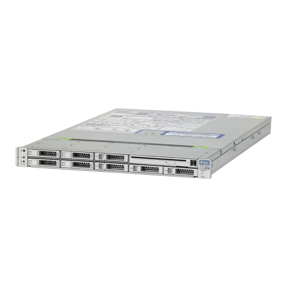
Sun Fire X4140 Server Front Panel Features shows front panel features on the Sun Fire X4140 Server. FIGURE 1-3 Front Panel Features FIGURE 1-3 Figure Legend Locator LED/Locator button (white) Drive map Service Action Required LED (amber) Power Supply Service Required LED (amber) -
Page 21: Sun Fire X4140 Server Rear Panel Features
Sun Fire X4140 Server Rear Panel Features shows rear panel features on the Sun Fire X4140 Server. For more detailed FIGURE 1-4 information about ports and their uses, see the Sun Fire X4150 Server Installation Guide. For a detailed description of PCIe slots, see Section 4.4.1, “Sun Fire X4140 Server PCIe... -
Page 22: Illustrated Parts Breakdown
Sun Fire X4140 Server I/O Components FIGURE 1-5 Figure Legend Top Cover Hard Drives or Solid-State Drives Disk Cage DVD/USB Module Left Control Panel Light Pipe Assembly Right Control Panel Light Pipe Assembly 1-10 Sun Fire X4140 Server Service Manual • September 2010... - Page 23 Power Distribution and Fan Module Components FIGURE 1-6 Figure Legend Paddle Card Power Supplies Power Distribution Board/Bus Bar Assembly Fan Modules Air Baffle Fan Boards Chapter 1 Sun Fire X4140 Server Overview 1-11...
- Page 24 1-12 Sun Fire X4140 Server Service Manual • September 2010...
-
Page 25: Preparing To Service The System
C H A P T E R Preparing to Service the System This chapter describes how to prepare the Sun Fire X4140 Server for servicing. The following topics are covered: Section 2.1, “Safety Information” on page 2-1 ■ Section 2.2, “Required Tools” on page 2-2 ■... -
Page 26: Required Tools
Follow the electrostatic discharge safety practices as described in this chapter. ■ Required Tools The Sun Fire X4140 Server can be serviced with the following tools: Antistatic wrist strap ■ Antistatic mat ■... -
Page 27: To View Chassis Serial Number
▼ To View Chassis Serial Number To view information about a system component, you need the Read Only (o) role enabled. 1. Log in to the ILOM CLI. 2. At the prompt, type: -> cd /SYS /SYS -> cd MB /SYS/MB ->... -
Page 28: Powering Off The Server Using The Service Processor Command Line
Refer to your application documentation for specific information. 4. Shut down all logical domains. 5. Shut down the Solaris operating system. 6. Open an SSH session. 7. Log into the Service Processor. 8. Type: stop /SYS Sun Fire X4140 Server Service Manual • September 2010... -
Page 29: Line
Extending the Server to the Maintenance Position The following components can be serviced with the server in the maintenance position: Hard drives ■ SSDs ■ Fan modules ■ Power supplies ■ DVD/USB module ■ Fan power boards ■ DDR2 DIMMs ■... -
Page 30: Removing A Server From The Rack
Power distribution board ■ Paddle card ■ Disk cage ■ Drives backplane ■ Front panel light-pipe assemblies ■ Caution – If necessary, use two people to dismount and carry the chassis. Sun Fire X4140 Server Service Manual • September 2010... - Page 31 To remove a server from the rack: 1. Disconnect all cables and power cords from the server. 2. Extend the lower floor arm on the cabinet for safety, if present. 3. Extend the server to the maintenance position. Section 2.5, “Extending the Server to the Maintenance Position” on page 2-5.
-
Page 32: Performing Electrostatic Discharge And Antistatic Prevention Measures
Electrostatic discharge (ESD) sensitive devices, such as the motherboards, PCI cards, hard drives, SSDs, and memory cards, require special handling. Caution – You must disconnect both power supplies before servicing any of the components documented in this chapter. Sun Fire X4140 Server Service Manual • September 2010... -
Page 33: Using An Antistatic Wrist Strap
Caution – Circuit boards, hard drives, and SSDs contain electronic components that are extremely sensitive to static electricity. Ordinary amounts of static electricity from clothing or the work environment can destroy the components located on these boards. Do not touch the components without ESD precautions, especially along the connector edges. -
Page 34: Removing The Top Cover
Caution – If the top cover is removed before the server is powered off, the server will immediately go into Standby mode. Removing the Sun Fire X4140 Server Top Cover FIGURE 2-6 2-10 Sun Fire X4140 Server Service Manual • September 2010... - Page 35 Chapter 2 Preparing to Service the System 2-11...
- Page 36 2-12 Sun Fire X4140 Server Service Manual • September 2010...
-
Page 37: Servicing Customer-Replaceable Devices
C H A P T E R Servicing Customer-Replaceable Devices This chapter describes how to replace the hot-swappable and hot-pluggable customer-replaceable units (CRUs) in the Sun Fire X4140 Server. The following topics are covered: Section 3.1, “Devices That Are Hot-Pluggable or Hot-Swappable” on page 3-1 ■... -
Page 38: Hot-Swappable Devices
In the Sun Fire X4140 Server, drives are hot-pluggable. To hot-plug a drive you must take the drive offline (to prevent any applications from accessing it, and to remove the logical software links to it) before you can safely remove it. See Section 3.2,... -
Page 39: Sun Fire X4140 Server Solid-State Drive Guidelines
TABLE 3-1 SSD1 SSD3 DVD drive SSD0 SSD2 The Sun Fire X4140 servers support solid-state drives (SSDs) under the following conditions: Sun Fire X4140 with on-board controller: No SSDs can be installed. ■ Sun Fire X4140 with HBA: One to 4 SSDs can be installed. The remaining slots can be filled with hard drives ■... -
Page 40: Ssd Firmware Requirements
When replacing or installing a SSD to be included in a RAID configuration, in the Sun Fire X4140 system, make sure that the firmware on the newly installed SSD is the same as the firmware that is installed on the other SSDs in the RAID volume. -
Page 41: Drive Status Led Reference
3.2.4 Removing a Hard Drive or SSD Drives can be hot-plugged or cold-plugged. Drives in the Sun Fire X4140 Server might be hot-pluggable, depending on the drive configuration. To hot-plug a drive you must take the drive offline (to prevent any applications from accessing it, and to remove the logical software links to it) before you can safely remove it. - Page 42 5. Grasp the latch [2] and pull the drive out of the drive slot [3]. Caution – The latch is not an ejector. Do not bend it too far to the right. Doing so can damage the latch. Sun Fire X4140 Server Service Manual • September 2010...
-
Page 43: Installing A Hard Drive Or Ssd
3.2.5 Installing a Hard Drive or SSD Installing a drive into the Sun Fire X4140 Server is a two-step process. You must first install a drive into the drive slot, and then configure that drive to the server. Caution – Before inserting a replacement drive, wait 15 seconds, and verify that your monitoring/administration application has detected the missing/failed drive. -
Page 44: Using Drive Fillers
All drive slots in the Sun Fire X4240 Server must have drive fillers in place during operation to maintain airflow. To remove fillers, pull the ejector and pull the filler out of the chassis. ( FIGURE 3-5 Sun Fire X4140 Server Service Manual • September 2010... -
Page 45: Servicing Fan Modules
Drive Filler FIGURE 3-5 Servicing Fan Modules The following topics are covered: Section 3.3.1, “About Sun Fire X4140 Server Fans” on page 3-9 ■ Section 3.3.2, “Fan Module LED Reference” on page 3-10 ■ Section 3.3.3, “Detecting Fan Module Failure” on page 3-11 ■... -
Page 46: Fan Module Led Reference
The fan module is faulty. The front and rear panel Service Required LEDs are also lit if the system detects a fan module fault. Fan Module Status LEDs FIGURE 3-6 3-10 Sun Fire X4140 Server Service Manual • September 2010... -
Page 47: Detecting Fan Module Failure
Section 1.2, “Sun Fire X4140 Server Chassis Overview” on page 1-3 for more information about system status LEDs. 3.3.3 Detecting Fan Module Failure The following LEDs are lit when a fan module fault is detected: Front and rear Service Required LEDs ■... -
Page 48: Installing A Fan Module
1. With the top cover door open, install the replacement fan module into the server FIGURE 3-8 The fan modules are keyed to ensure that they are installed in the correct orientation. 3-12 Sun Fire X4140 Server Service Manual • September 2010... - Page 49 4. Close the top cover door. 5. Verify that the Top Fan LED, Service Required LEDs, and the Locator LED/Locator button are not lit. Section 1.3, “Sun Fire X4140 Server Front Panel Features” on page 1-8 for more information about identifying and interpreting system LEDs.
-
Page 50: Servicing Power Supplies
Servicing Power Supplies Some versions of the Sun Fire X4140 Servers are equipped with redundant hot-swappable power supplies. Redundant power supplies enable you to remove and replace a power supply without shutting the server down, if the other power supply is online and working. -
Page 51: Removing A Power Supply
Power Supply Status LEDs FIGURE 3-9 Figure Legend Legend Symbol Color Lights when OK to Remove Blue A power supply can be removed safely during a hot–swap operation. Service Required Amber The power supply is faulty. The front and rear panel Service Required LEDs are also lit if the system detects a power supply fault. - Page 52 4. Disconnect the power cord from the faulty power supply. 5. Grasp the power supply handle and press the release latch ( FIGURE 3-11 6. Pull the power supply out of the chassis. 3-16 Sun Fire X4140 Server Service Manual • September 2010...
-
Page 53: Installing A Power Supply
Power Supply Release Handle FIGURE 3-11 3.4.4 Installing a Power Supply 1. Align the replacement power supply with the empty power supply chassis bay. 2. Slide the power supply into the bay until it is fully seated ( FIGURE 3-12 Chapter 3 Servicing Customer-Replaceable Devices 3-17... - Page 54 Rear Service Required LED ■ Note – See Section 1.3, “Sun Fire X4140 Server Front Panel Features” on page 1-8 Section 1.4, “Sun Fire X4140 Server Rear Panel Features” on page 1-9 for more information about identifying and interpreting system LEDs.
-
Page 55: Servicing Motherboard Components
C H A P T E R Servicing Motherboard Components This chapter describes how to replace the motherboard and its components in the Sun Fire X4140 Server. Note – Before performing any of the procedures in this chapter, perform the procedures described in... -
Page 56: Servicing Ddr2 Dimms
2-9. 4.1.1 Identifying Faulty DDR2 DIMMs The Sun Fire X4140 Server Service Required LED is lit if the system detects a DDR2 DIMM fault. To use the rear panel Locator button to identify faulty DDR2 DIMMs: 1. Unplug all power cords from the rear panel. -
Page 57: Ddr2 Dimm Guidelines
Note – Refer to the Sun Fire X4140, X4240, and X4440 Servers Diagnostics Guide for more information about DIMM System Event Log (SEL) messages. Remind Button FIGURE 4-1 4.1.2 DDR2 DIMM Guidelines Use the DDR2 DIMM guidelines, and to help you plan the memory FIGURE 4-2 configuration of your server. -
Page 58: Viewing The Memory Configuration
DRAMs; single-rank DIMMs, have 18 DRAMs, while dual-rank DIMMs have 36 DRAMs. Refer to the service label on the cover for DDR2 DIMM placement information. Refer to the Sun Fire X4140, X4240, and X4440 Servers Diagnostics Guide for additional DDR2 DIMM information. DDR2 DIMM Layout FIGURE 4-2 4.1.2.1... -
Page 59: Single Processor Configuration Ddr2 Dimm Placement
/SYS/MB/P0/D0 Targets: SERVICE Properties: type = DIMM fru_name = 2048MB DDR-II 666 fru_manufacturer = Hynix Semiconductor Inc. fru_version = 4141 fru_part_number = HYMP525P72CP4-Y5 fru_serial_number = 00005092 Commands: show -> Note – DDR2 DIMM names in Integrated LOM messages are displayed with the full name, such as /SYS/MB/DIMM_D0 4.1.2.2... -
Page 60: Removing Ddr2 Dimms
4. Push down on the ejector tabs on each side of the DDR2 DIMM until the FB-DIMM is released ( FIGURE 4-3 5. Grasp the top corners of the faulty DDR2 DIMM and remove it from the server. Sun Fire X4140 Server Service Manual • September 2010... -
Page 61: Installing Ddr2 Dimms
Removing DDR2 DIMMs FIGURE 4-3 6. Place the DDR2 DIMM on an antistatic mat. 7. Repeat Step 4 through Step 6 to remove any additional DDR2 DIMMs. 4.1.4 Installing DDR2 DIMMs Caution – Ensure that all power is removed from the server before removing or installing DDR2 DIMMs, or damage to the DDR2 DIMMs might occur. - Page 62 Verify that the AC Present LED is lit. Section 6.4, “Powering On the Server” on page 6-5. 9. Power on the server. Section 6.4, “Powering On the Server” on page 6-5. Sun Fire X4140 Server Service Manual • September 2010...
-
Page 63: Installing Additional Ddr2 Dimms
Installing DDR2 DIMMs FIGURE 4-4 4.1.5 Installing Additional DDR2 DIMMs Before you begin, see Section 4.1.2, “DDR2 DIMM Guidelines” on page 4-3, for information about DDR2 DIMM configuration guidelines. Caution – Ensure that all power is removed from the server before installing DDR2 DIMMs or damage to the DDR2 DIMMs might occur. -
Page 64: Servicing The Air Baffle
Note – CRU: This customer-replaceable unit can be replaced by anyone. Caution – To prevent the system from overheating, ensure that the air baffle is correctly installed before powering on the server. 4-10 Sun Fire X4140 Server Service Manual • September 2010... -
Page 65: Removing The Air Baffle
4.2.1 Removing the Air Baffle 1. Prepare the server for service. a. Power off the server. Section 2.4, “Powering Off the Server” on page 2-4. b. Disconnect the power cord (or cords) from the power supply (or supplies). Section 2.4, “Powering Off the Server” on page 2-4. -
Page 66: Installing The Air Baffle
Verify that the AC Present LED is lit. Section 6.4, “Powering On the Server” on page 6-5. d. Power on the server. Section 6.4, “Powering On the Server” on page 6-5. Installing the Air Baffle FIGURE 4-6 4-12 Sun Fire X4140 Server Service Manual • September 2010... -
Page 67: Servicing Pcie Risers
Servicing PCIe Risers The following topics are covered: Section 4.3.1, “Removing a PCIe Riser” on page 4-13 ■ Section 4.3.2, “Installing a PCIe Riser” on page 4-14 ■ PCIe cards are installed on vertical risers. You must remove the relevant riser to access a PCIe card. -
Page 68: Installing A Pcie Riser
Installing a PCIe Riser Caution – Ensure that all power is removed from the server before removing or installing risers. You must disconnect the power cables before performing this procedure. 4-14 Sun Fire X4140 Server Service Manual • September 2010... -
Page 69: Servicing Pcie Cards
Installing a PCIe Riser FIGURE 4-8 Servicing PCIe Cards The following topics are covered: Section 4.4.1, “Sun Fire X4140 Server PCIe Card Guidelines” on page 4-16 ■ Section 4.4.2, “Removing PCIe Cards” on page 4-17 ■ Section 4.4.3, “Installing PCIe Cards” on page 4-18 ■... -
Page 70: Sun Fire X4140 Server Pcie Card Guidelines
The SGXPCIESAS-R-INT-Z HBA should be installed in slot 0 to avoid system overheating. Make sure that the firmware is at SW 3.1 or later when installing the HBA in Slot 0. 4-16 Sun Fire X4140 Server Service Manual • September 2010... -
Page 71: Removing Pcie Cards
1. Locate the PCIe card that you want to remove, and note its corresponding riser board. Section 1.4, “Sun Fire X4140 Server Rear Panel Features” on page 1-9 for more information about PCIe slots and their locations. 2. If necessary, make a note of where the PCIe cards are installed. -
Page 72: Installing Pcie Cards
2. Locate the proper PCIe slot for the card you are replacing. 3. If necessary, review the PCIe Card Guidelines to plan your installation. Section 4.4.1, “Sun Fire X4140 Server PCIe Card Guidelines” on page 4-16 additional information. 4. Remove the PCIe riser board. -
Page 73: Servicing The Battery
Installing a PCIe Card FIGURE 4-10 Servicing the Battery The following topics are covered: Section 4.5.1, “Removing the Battery” on page 4-20 ■ Section 4.5.2, “Installing the Battery” on page 4-20 ■ The battery maintains system time when the server is powered off and a time server is unavailable. -
Page 74: Removing The Battery
1. Remove PCIe riser 0. Section 4.3.1, “Removing a PCIe Riser” on page 4-13. Section 4.4.1, “Sun Fire X4140 Server PCIe Card Guidelines” on page 4-16. 2. Using a small (No. 1 flat-blade) screwdriver, press the latch and remove the battery from the motherboard. -
Page 75: Servicing The Motherboard Assembly
3. Install PCIe riser 0. Section 4.3.2, “Installing a PCIe Riser” on page 4-14. 4. Use the ILOM command to set the day and time. Type: -> set /SP/clock datetime=MMDDhhmmYYYY (or MMDDhhmmYYYY.ss) Servicing the Motherboard Assembly This section describes the following procedures: Section 4.6.1, “Removing the Motherboard Assembly”... -
Page 76: Removing The Motherboard Assembly
Caution – The drive data cables are delicate. Ensure they are safely out of the way when servicing the motherboard. 7. Remove the processor heat sinks from the motherboard assembly. 4-22 Sun Fire X4140 Server Service Manual • September 2010... - Page 77 8. Remove the 4 screws that secure the motherboard to the bus bar. Use a No. 2 Phillips screwdriver. 9. Loosen the green captive screw on the front of the motherboard, that secures the motherboard tray to the chassis. 10. Remove the plastic air flow bezel from between the fans and the motherboard. 11.
-
Page 78: Installing The Motherboard Assembly
Section 2.7, “Performing Electrostatic Discharge and Antistatic Prevention Measures” on page 2-9. 3. Place the motherboard into the chassis ( FIGURE 4-13 Position the motherboard carefully. Installing the Motherboard Assembly FIGURE 4-13 4-24 Sun Fire X4140 Server Service Manual • September 2010... - Page 79 4. Install the 4 screws that secure the motherboard to the bus bar. Torque screws to 7 inch-pounds (0.8 newton-meters). Use a manual torque driver settable to 7 inch-lbs (0.8 newton-meters) with a No. 2 Phillip screwdriver. 5. Tighten the green captive screw on the front of the motherboard, that secures the motherboard tray to the chassis.
-
Page 80: Servicetool Fru Update Procedures
Caution – The SunService account is for the use of Sun service representatives only. Do not use the SunService account unless you are instructed to do so in a procedure developed by Sun Microsystems. 4-26 Sun Fire X4140 Server Service Manual • September 2010... -
Page 81: Updating Fru Product Information Using Servicetool
Note – If your system is running ILOM 3.x, then you must re-enable your SunService account. Note – Before beginning these procedures, obtain Service/Escalation passwords from the Customer Support Center. 4.7.1 Updating FRU Product Information Using ServiceTool 1. Use SSH to log into the SunService account. The default password is changeme. # ssh <SP IP address>... -
Page 82: Restoring Product Information From The Fruid Prom
4. View the file by issuing the following command to verify the previous step was successful: # cat /dev/shm/product.info 5. Write the product information to the motherboard by issuing this command: # frutool -t mb --write_cmm_product_area < /dev/shm/product.info 4-28 Sun Fire X4140 Server Service Manual • September 2010... - Page 83 6. View the file to ensure that the product data has been updated in the motherboard FRUID PROM: # frutool -r mb | hexdump -C | egrep ’^000004’ 00000400 00 00 00 00 00 00 00 00 00 00 00 00 00 a4 70 72 |....pr| 00000410 6f 64 75 63 74 20 70 61...
-
Page 84: Servicing Processors
Disconnect the power cord (or cords) from the power supply (or supplies). Section 2.4, “Powering Off the Server” on page 2-4. c. Slide the server out of the rack. Section 2.5, “Extending the Server to the Maintenance Position” on page 2-5. 4-30 Sun Fire X4140 Server Service Manual • September 2010... -
Page 85: Installing A Processor Fru
d. Attach an antistatic wrist strap. Section 2.7, “Performing Electrostatic Discharge and Antistatic Prevention Measures” on page 2-9. e. Remove the top cover. Section 2.8, “Removing the Top Cover” on page 2-11. 2. Identify which processor to remove. Processor 0 is closest to the PSU bay. 3. - Page 86 Verify that the AC Present LED is lit. Section 6.4, “Powering On the Server” on page 6-5. d. Power on the server. Section 6.4, “Powering On the Server” on page 6-5. 4-32 Sun Fire X4140 Server Service Manual • September 2010...
-
Page 87: Installing An Xoption Processor
4.8.4 Installing an XOption Processor 1. Prepare the server for service. a. Power off the server. Section 2.4, “Powering Off the Server” on page 2-4. b. Disconnect the power cord (or cords) from the power supply (or supplies). Section 2.4, “Powering Off the Server” on page 2-4. -
Page 88: Resetting Passwords And Clearing Cmos Nvram
ILOM password. To reset a password for the BIOS, access the BIOS Security screen. 1. Boot the server. 2. Press F2 at the Sun splash screen to enter Setup. 4-34 Sun Fire X4140 Server Service Manual • September 2010... -
Page 89: Resetting Cmos Nvram Using A Jumper
3. At the BIOS screen, move to the Security Screen tab. 4. Change the password. 5. Save and Exit the BIOS. The system restarts. 4.9.3 Resetting CMOS NVRAM Using a Jumper To clear the CMOS NVRAM using a jumper: 1. Power off the server. Section 2.4, “Powering Off the Server”... -
Page 90: Recovering From Corrupt Service Processor Software
DOS4GW ■ BMC Binary (the SP Binary file) ■ 2. Insert the bootable flash drive into the USB port. a. Press F8 to get a list of the boot devices. 4-36 Sun Fire X4140 Server Service Manual • September 2010... - Page 91 b. Choose the USB flash boot device. a. Press F2 to enter the BIOS setup screen. b. Choose the USB flash device as the first boot device. c. Save and exit. FIGURE 4-15 3. Once the flash device is booted, run the following command: socflash -p 1 -f <sp-binary-file>...
-
Page 92: Using The Reset And Nmi Switches
4.11 Using the Reset and NMI Switches Caution – Do not use the Reset and NMI Dump switches unless you are instructed to do so by a Field Service engineer. 4-38 Sun Fire X4140 Server Service Manual • September 2010... -
Page 93: Reset Switch
4.11.1 Reset Switch The Reset switch (SW2 on the motherboard) sends a reset order to the processors, resetting the main system, but not the service processor. The button for this switch can be pushed by sticking a paper clip or similar object through the hole provided on the rear of the chassis. - Page 94 4-40 Sun Fire X4140 Server Service Manual • September 2010...
-
Page 95: Servicing Infrastructure Boards And Components
C H A P T E R Servicing Infrastructure Boards and Components This chapter describes how to replace cold-swappable, field-replaceable units (FRUs) in the Sun Fire X4140 Server. The following topics are covered: Section 5.1, “Servicing the DVD/USB Module” on page 5-2 (CRU) ■... -
Page 96: Servicing The Dvd/Usb Module
Section 2.7, “Performing Electrostatic Discharge and Antistatic Prevention Measures” on page 2-9. 4. Remove the Sun Fire X4140 Server HDD7 hard drive. “Server Front Panel” on page 3-3 for drives locations. 5. Release the DVD/USB module from the drives backplane (... -
Page 97: Installing The Dvd/Usb Module
Removing the DVD/USB Module FIGURE 5-1 5.1.2 Installing the DVD/USB Module 1. Slide the DVD/USB module into the front of the chassis until it seats FIGURE 5-2 2. Install the drive you removed during the DVD/USB module removal procedure. Section 3.2.5, “Installing a Hard Drive or SSD” on page 3-7 for information about installing a drive. -
Page 98: Servicing The Fan Power Boards
Servicing the Fan Power Boards You must remove both fan power boards to access the paddle card or to access the drives data cables in the Sun Fire X4140 Server. Note – FRU: This field-replaceable unit should be replaced only by qualified service technicians. -
Page 99: Removing A Fan Power Board
5.2.1 Removing a Fan Power Board 1. Prepare the server for service. a. Power off the server. Section 2.4, “Powering Off the Server” on page 2-4. b. Disconnect the power cord (or cords) from the power supply (or supplies). Section 2.4, “Powering Off the Server” on page 2-4. -
Page 100: Installing A Fan Power Board
2. Secure the board to the chassis with a Phillips screw. 3. Reinstall the fan modules. Section 3.3.5, “Installing a Fan Module” on page 3-12. 4. Return the server to operation. Sun Fire X4140 Server Service Manual • September 2010... -
Page 101: Servicing The Drives Cage
a. Install the top cover. Section 6.1, “Installing the Top Cover” on page 6-2. b. Slide the server into the rack. Section 6.3, “Returning the Server to the Normal Rack Position” on page 6-4. c. Reconnect the power cord (or cords) to the power supply (or supplies). Verify that the AC Present LED is lit. - Page 102 7. Lift the drives cage up and disconnect the drives data cables ( [4]). FIGURE 5-5 Press the connector release button to release the cable. 8. Set the drives cage on an antistatic mat. Sun Fire X4140 Server Service Manual • September 2010...
-
Page 103: Installing The Drives Cage
Removing the Drives Cage FIGURE 5-5 5.3.2 Installing the Drives Cage 1. Connect the drives data cables. Press the connector into its socket until it snaps into place. 2. Position the drives cage in the chassis, over its standoffs ( [1]). - Page 104 5. Install the fan power boards. Section 5.2.2, “Installing a Fan Power Board” on page 5-6. 6. Install the fan modules. Section 3.3.5, “Installing a Fan Module” on page 3-12. 5-10 Sun Fire X4140 Server Service Manual • September 2010...
-
Page 105: Servicing The Drives Backplane
7. Install the top cover. Section 6.1, “Installing the Top Cover” on page 6-2. 8. Install the server into the rack. Section 6.2, “Reinstalling the Server in the Rack” on page 6-3. 9. Install the drives. Note – Ensure you are installing the drives in the correct drive bays. Section 3.2.5, “Installing a Hard Drive or SSD”... -
Page 106: Installing The Drives Backplane
2. Install the two No. 2 Phillips screws that secure the backplane to the drives cage. 3. Install the drives cage. Section 5.3.2, “Installing the Drives Cage” on page 5-9. 5-12 Sun Fire X4140 Server Service Manual • September 2010... -
Page 107: Servicing The Front Control Panel Light Pipe Assembly
Installing the Drives Backplane FIGURE 5-8 Servicing the Front Control Panel Light Pipe Assembly You must remove the drives backplane to service the front control panel light pipe assemblies. Note – FRU: This field-replaceable unit should be replaced only by qualified service technicians. -
Page 108: Removing The Front Control Panel Light Pipe Assembly
For replacement, ensure the board is aligned and Caution light pipes are exposed. Pay close attention when inserting the assembly. 1. Align the light pipe assembly with the mounting holes on the drives cage. 5-14 Sun Fire X4140 Server Service Manual • September 2010... -
Page 109: Servicing The Power Distribution Board (Pdb)
2. Secure the light pipe assembly with two No. 2 Phillips screws. 3. Install the drives backplane. Section 5.4.2, “Installing the Drives Backplane” on page 5-12. 4. Install the drives cage. Section 5.3.2, “Installing the Drives Cage” on page 5-9. Servicing the Power Distribution Board (PDB) It is easier to service the power distribution board (PDB) with the bus bar assembly... -
Page 110: Installing The Power Distribution Board
2. Slide the PDB/bus bar assembly to the right, until it plugs into the paddle card. 3. Install the No. 2 Phillips screw to secure the PDB to the chassis. 5-16 Sun Fire X4140 Server Service Manual • September 2010... -
Page 111: Servicing The Paddle Card
4. Connect the top cover interlock cable to the power distribution board. Installing the Power Distribution Board FIGURE 5-11 5. Install the power supplies. Slide each power supply into its bay until it locks into place. Section 3.4.4, “Installing a Power Supply” on page 3-17. -
Page 112: Removing The Paddle Card
5. Slide the paddle card back, away from its connector on the drives backplane. 6. Lift the paddle card up and out of the chassis. 7. Place the paddle card on an antistatic mat. Removing the Paddle Card FIGURE 5-12 5-18 Sun Fire X4140 Server Service Manual • September 2010... -
Page 113: Installing The Paddle Card
5.7.2 Installing the Paddle Card 1. Lower the paddle card into the chassis. The paddle card fits over a series of mushroom standoffs in the chassis side wall. 2. Slide the paddle card forward to plug it into the drives backplane. ( FIGURE 5-13 3. -
Page 114: Removing Hdd Cables In A Sas Configuration
4. Remove the fans from fan board 0. 5. Disconnect each cable at the Hard Disk Drive backplane by pressing down on the latch and then pulling out the connector. 5-20 Sun Fire X4140 Server Service Manual • September 2010... -
Page 115: Installing Hdd Cables In A Sas Configuration
6. Remove the cables. Do not snag the cables on the retainer above the midwall. 5.8.2 Installing HDD Cables in a SAS Configuration To install two Hard Disk Drive cables; Disk 0-3 and Disk 4-7 in a SAS configuration, do the following. 1. -
Page 116: Removing Hdd Cables In A Sata Configuration
7. Disconnect each cable at Hard Disk Drive backplane by pressing down on the latch and then pulling out the connector. 8. Remove the cables. Do not snag the cables on the retainer above the mid-wall. 5-22 Sun Fire X4140 Server Service Manual • September 2010... -
Page 117: Installing Hdd Cables In A Sata Configuration
5.8.4 Installing HDD Cables in a SATA Configuration To install two Hard Disk Drive cables, Disk 0-3 and Disk 4-5 in SATA configuration, do the following. 1. Install the disk 0-3 cable. a. Install the connector in the Hard Disk Drive backplane. The connector is on the left from the front of the server. -
Page 118: Removing A Pdb Cable
Grasp each end of the connector on the motherboard, and then pull straight up to disconnect from connector. Caution – Do not to bend the pins on the unshrouded motherboard connector. 5-24 Sun Fire X4140 Server Service Manual • September 2010... -
Page 119: Installing A Pdb Cable
Removing the PDB Cable FIGURE 5-14 5.8.6 Installing a PDB Cable To install a Power Distribution Board cable. 1. Remove the PDB cable. 2. Inspect the motherboard pin field to ensure that all pins are straight. Chapter 5 Servicing Infrastructure Boards and Components 5-25... - Page 120 Verify that the AC Present LED is lit. Section 6.4, “Powering On the Server” on page 6-5. d. Power on the server. Section 6.4, “Powering On the Server” on page 6-5. 5-26 Sun Fire X4140 Server Service Manual • September 2010...
-
Page 121: Returning The Server To Operation
C H A P T E R Returning the Server to Operation This chapter describes how to return the Sun Fire X4140 Server to operation after you have performed service procedures. The following topics are covered in this chapter: Section 6.1, “Installing the Top Cover” on page 6-2 ■... -
Page 122: Installing The Top Cover
3. Close the fan cover. Caution – If the top cover is not installed correctly, and the cover is not completely closed, the server will not power on. Installing the Top Cover FIGURE 6-1 Sun Fire X4140 Server Service Manual • September 2010... -
Page 123: Reinstalling The Server In The Rack
Reinstalling the Server in the Rack If you removed the server chassis from the rack, perform these steps. Caution – The servers are heavy. Two people might be required to carry the chassis and install it in the rack. 1. On the rack, ensure that the slide rails are extended. 2. -
Page 124: Returning The Server To The Normal Rack Position
FIGURE 6-3 Release Tabs on Rails FIGURE 6-3 2. While pushing on the release tabs, slowly push the server into the rack. Ensure that the cables do not get in the way. Sun Fire X4140 Server Service Manual • September 2010... -
Page 125: Powering On The Server
Powering On the Server Before powering on your server for the first time, follow the installation and cabling instructions provided in the Sun Fire X4140 Server Installation Guide, which is shipped with the system and is also available online. To connect power cords and apply power to the server: 1. - Page 126 Power/OK LED Front Panel FIGURE 6-5 Sun Fire X4140 Server Service Manual • September 2010...
-
Page 127: Connector Pinouts
A P P E N D I X Connector Pinouts This appendix provides reference information about the Sun Fire X4140 Server rear panel ports and pin assignments. Topics covered in this appendix include: Section A.1, “Serial Management Port Connector” on page A-2 ■... -
Page 128: Serial Management Port Connector
Serial Management Connector Diagram FIGURE A-2 Serial Management Connector Pins TABLE A-1 Signal Description Signal Description Request to Send Ground Data Terminal Ready Receive Data Transmit Data Data Set Ready Ground Clear to Send Sun Fire X4140 Server Service Manual • September 2010... -
Page 129: Network Management Port Connector
Network Management Port Connector The network management connector (labeled NET MGT) is an RJ-45 connector located on the motherboard and can be accessed from the rear panel. This port needs to be configured prior to use. Network Management Connector Diagram FIGURE A-3 Network Management Connector Signals TABLE A-2... -
Page 130: Video Connector
Sync Ground Blue Video Monitor ID - Bit 1 Monitor ID - Bit 2 Monitor ID - Bit 0 Ground Horizontal Sync Red Ground Vertical Sync Green Ground N/C (Reserved) Blue Ground Sun Fire X4140 Server Service Manual • September 2010... -
Page 131: Usb Connectors
USB Connectors Two Universal Serial Bus (USB) ports are located on the motherboard in a double- stacked layout and can be accessed from the rear panel. USB Connector Diagram FIGURE A-5 USB Connector Signals TABLE A-4 Signal Description Signal Description +5 V (fused) +5 V (fused) USB0/1-... -
Page 132: Gigabit Ethernet Connectors
Transmit/Receive Data 0 + Transmit/Receive Data 2 – Transmit/Receive Data 0 – Transmit/Receive Data 1 – Transmit/Receive Data 1 + Transmit/Receive Data 3 + Transmit/Receive Data 2 + Transmit/Receive Data 3 – Sun Fire X4140 Server Service Manual • September 2010... -
Page 133: Bios Power-On Self-Test (Post) Codes
A P P E N D I X BIOS Power-On Self-Test (POST) Codes The system BIOS provides a basic power-on self-test (POST), during which the BIOS checks the basic devices required for the server to operate. The progress of the self- test is indicated by a series of POST codes. -
Page 134: How Bios Post Memory Testing Works
4. Initialize the BIOS Setup Utility by pressing the F2 key while the system is performing the power-on self-test (POST). The BIOS Main Menu screen appears. 5. Select Server. The Server screen appears. 6. Select AST2000 LAN Configuration. The LAN Configuration screen appears. Sun Fire X4140 Server Service Manual • September 2010... -
Page 135: Changing Post Options
7. Select the IP Address menu item. The SP’s IP address appears 8. Start a web browser and type the SP’s IP address in the browser’s address bar. 9. Type a user name and password as follows: User name: root Password: changeme 10. -
Page 136: Post Codes
Interrupt 19 Capture: This option is reserved for future use. Do not change. ■ POST Codes For more information on POST codes, POST checkpoints, and POST error codes, see Sun Fire™ X4140, X4240, and X4440Servers Diagnostics Guide. Sun Fire X4140 Server Service Manual • September 2010... -
Page 137: Bios Screens
(POST). When BIOS is started, the main BIOS Setup menu screen is displayed. Note – Refer to the Sun Fire X4140, X4240, and X4440 Servers Diagnostics Guide for more information about POST messages and System Event Log (SEL) messages. - Page 138 6. Press and release the right arrow key until the Exit menu screen appears. 7. Follow the instructions on the Exit menu screen to save your changes and exit the Setup utility. Sun Fire X4140 Server Service Manual • September 2010...
-
Page 139: Bios Setup Screens Overview
C.1.2 BIOS Setup Screens Overview contains summary descriptions of the top-level BIOS setup screens. TABLE C-1 BIOS Setup Screens Summary TABLE C-1 Screen Description See... Main General product information, including Section C.2.1, “BIOS Main BIOS type, processor, memory, and Menu Screens” on page C-5 time/date. - Page 140 BIOS Utility Menu Tree FIGURE C-1 Sun Fire X4140 Server Service Manual • September 2010...
-
Page 141: Bios Setup Menu Screens
The following figures show sample BIOS Setup Utility screens. Sun Fire X4140 Server Note – The screens shown are examples. The version numbers and the screen items and selections shown are subject to change over the life of the product. -
Page 142: Bios Advanced Menu Screens
Note – The term BMC that may be displayed on some screens refers to the SP (service processor). Note – Refer to the Sun Fire X4140, X4240, and X4440 Servers Diagnostics Guide for more information about POST (Power On Self Test) messages and System Event Log (SEL) messages. - Page 143 BIOS Setup Utility: Advanced- CPU Configuration FIGURE C-4 BIOS Setup Utility: Advanced- IDE Configuration FIGURE C-5 Appendix C BIOS Screens...
- Page 144 BIOS Setup Utility: Advanced- Hyper Transport Configuration FIGURE C-6 BIOS Setup Utility: Advanced- ACPI Settings FIGURE C-7 Sun Fire X4140 Server Service Manual • September 2010...
- Page 145 BIOS Setup Utility: Advanced- ACPI Configuration - Advanced ACPI FIGURE C-8 Configuration BIOS Setup Utility: Advanced- ACPI Configuration - Chipset ACPI FIGURE C-9 Configuration Appendix C BIOS Screens...
- Page 146 BIOS Setup Utility: Advanced- Event Logging Details - View FIGURE C-10 BIOS Setup Utility: Advanced- Event Logging Details - Mark FIGURE C-11 C-10 Sun Fire X4140 Server Service Manual • September 2010...
- Page 147 BIOS Setup Utility: Advanced- Event Logging Details - Clear FIGURE C-12 BIOS Setup Utility: Advanced- IPMI 2.0 Configuration FIGURE C-13 Appendix C BIOS Screens C-11...
- Page 148 BIOS Setup Utility: Advanced- IPMI 2.0 Configuration - System Event Logs FIGURE C-14 (SEL) BIOS Setup Utility: Advanced- IPMI 2.0 Configuration - Reload SEL FIGURE C-15 C-12 Sun Fire X4140 Server Service Manual • September 2010...
- Page 149 BIOS Setup Utility: Advanced- IPMI 2.0 Configuration - Clear BMC SEL FIGURE C-16 BIOS Setup Utility: Advanced- IPMI 2.0 Configuration - LAN Configuration FIGURE C-17 Appendix C BIOS Screens C-13...
- Page 150 BIOS Setup Utility: Advanced- IPMI 2.0 Configuration - Set PEF FIGURE C-18 Configuration BIOS Setup Utility: Advanced- IPMI 2.0 Configuration - Set PEF FIGURE C-19 Configuration Parameters C-14 Sun Fire X4140 Server Service Manual • September 2010...
- Page 151 BIOS Setup Utility: Advanced- IPMI 2.0 Configuration - PEF Action Global FIGURE C-20 Control BIOS Setup Utility: Advanced- IPMI 2.0 Configuration - PEF Event Message FIGURE C-21 Appendix C BIOS Screens C-15...
- Page 152 BIOS Setup Utility: Advanced- IPMI 2.0 Configuration - BMC Watch Dog FIGURE C-22 Timer Action BIOS Setup Utility: Advanced- MPS Revision FIGURE C-23 C-16 Sun Fire X4140 Server Service Manual • September 2010...
- Page 153 BIOS Setup Utility: Advanced- PCI Express Configuration FIGURE C-24 BIOS Setup Utility: Advanced- Remote Access Configuration FIGURE C-25 Appendix C BIOS Screens C-17...
- Page 154 BIOS Setup Utility: Advanced- USB Configuration FIGURE C-26 BIOS Setup Utility: Advanced- USB Mass Storage Device Configuration - FIGURE C-27 C-18 Sun Fire X4140 Server Service Manual • September 2010...
-
Page 155: Bios Pci/Pnp Menu Screens
Activating these features on a healthy system can result in an unstable execution, and are strictly for trained service personnel’s use. C.2.3 BIOS PCI/PnP Menu Screens The BIOS PCI/PnP screens allow you to set the PCI/PnP Configuration has the following BIOS PCI/PnP screens: Sun Fire X4140 Server Appendix C BIOS Screens C-19... -
Page 156: Bios Boot Menu Screens
BIOS Boot Menu Screens The BIOS Boot screens allow you to configure the boot device priority (hard disk drives and the DVD-ROM drive). has the following BIOS Boot screens: Sun Fire X4140 Server C-20 Sun Fire X4140 Server Service Manual • September 2010... - Page 157 BIOS Setup Utility: Boot FIGURE C-30 BIOS Setup Utility: Boot Settings Configuration FIGURE C-31 Appendix C BIOS Screens C-21...
- Page 158 BIOS Setup Utility: Boot Device Priority FIGURE C-32 BIOS Setup Utility: Boot Hard Disk Drives FIGURE C-33 C-22 Sun Fire X4140 Server Service Manual • September 2010...
-
Page 159: Bios Security Menu Screens
BIOS Setup Utility: Boot CD/DVD Drives FIGURE C-34 C.2.5 BIOS Security Menu Screens The BIOS Security screens allow you to set or change the user and supervisor passwords. has the following BIOS Security screens: Sun Fire X4140 Server Appendix C BIOS Screens C-23... -
Page 160: Bios Chipset Menu Screens
FIGURE C-35 C.2.6 BIOS Chipset Menu Screens The BIOS Server screens allow you to configure Server advanced chipset settings (if applicable). has the following BIOS screens: Sun Fire X4140 Server Chipset C-24 Sun Fire X4140 Server Service Manual • September 2010... - Page 161 BIOS Setup Utility: Chipset FIGURE C-36 BIOS Setup Utility: Chipset - Northbridge Configuration FIGURE C-37 Appendix C BIOS Screens C-25...
- Page 162 BIOS Setup Utility: Chipset - Northbridge Memory Configuration FIGURE C-38 BIOS Setup Utility: Chipset - Northbridge ECC Configuration FIGURE C-39 C-26 Sun Fire X4140 Server Service Manual • September 2010...
- Page 163 BIOS Setup Utility: Chipset - Northbridge DRAM Timing Configuration FIGURE C-40 BIOS Setup Utility: Chipset - Northbridge VID Configuration FIGURE C-41 Appendix C BIOS Screens C-27...
- Page 164 BIOS Setup Utility: Chipset - Southbridge Configuration FIGURE C-42 BIOS Setup Utility: Chipset - I055 Bridge Configuration FIGURE C-43 C-28 Sun Fire X4140 Server Service Manual • September 2010...
-
Page 165: Bios Exit Menu Screens
The BIOS Exit screens allow you to save changes and exit, discard changes and exit, discard changes, or load optimal or failsafe defaults. has the following BIOS Exit screens: Sun Fire X4140 Server BIOS Setup Utility: Exit FIGURE C-44 Appendix C... - Page 166 BIOS Setup Utility: Exit - Save Configuration Changes FIGURE C-45 BIOS Setup Utility: Help FIGURE C-46 C-30 Sun Fire X4140 Server Service Manual • September 2010...
- Page 167 Index DVD/USB module installing, 5-3 antistatic mat, 2-10 removing, 5-2 antistatic wrist strap, 2-9, 2-10 ejector tabs, 4-6 BIOS electrostatic discharge, 2-9 changing menu settings, C-1 ESD, 2-9 configuring, C-1 overview, C-1 POST codes, B-4 POST options, B-3 Fan Fault LED, 3-11 POST overview, B-1 fan tray connector board, 5-5, 5-6 redirecting console output for POST, B-2...
- Page 168 4-37 Locator LED/Locator button, 3-13 System Power Supply Failure LED, 3-14 maintenance position, 2-5, 2-8 Top Fan LED, 3-11, 3-13 NMI, 4-39 POST changing options, B-3 codes table, B-4 Index-2 Sun Fire X4140 Server Service Manual • September 2010...
Need help?
Do you have a question about the Sun Fire X4140 and is the answer not in the manual?
Questions and answers