Table of Contents
Advertisement
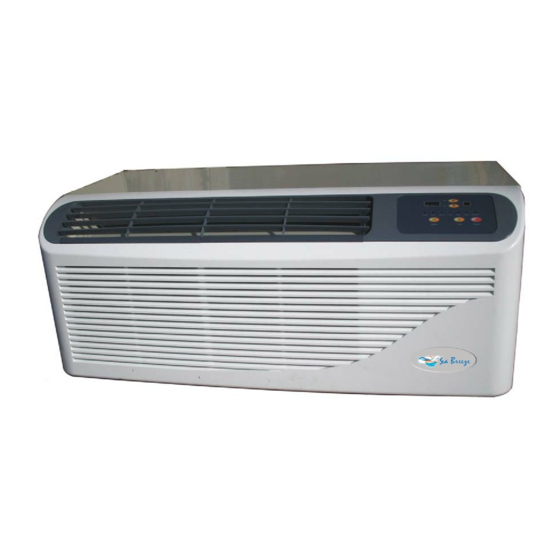
Installation and Operation Manual
Model
PTAC09CH3ZX
PTAC09HP3ZX
PTAC12CH3ZX
PTAC12CH5ZX
PTAC12HP3ZX
PTAC15CH3ZX
PTAC15CH5ZX
PTAC15HP3ZX
950-0094revF
Sea Breeze
PTAC Air Conditioners
9,000 BTU, cooling with 3,000 Watt PTC heater, 240 VAC
9,000 BTU, heat pump with 3,000 Watt PTC heater, 240 VAC
12,000 BTU, cooling with 3,000 Watt PTC heater, 240 VAC
12,000 BTU, cooling with 5,000 Watt PTC heater, 240 VAC
12,000 BTU, heat pump with 3,000 Watt PTC heater, 240 VAC
15,000 BTU, cooling with 3,000 Watt PTC heater, 240 VAC
15,000 BTU, cooling with 5,000 Watt PTC heater, 240 VAC
15,000 BTU, heat pump with 3,000 Watt PTC heater, 240 VAC
- 1 -
Sea Breeze
Description
November 26, 2008
Advertisement
Table of Contents

Related Manuals for Sea Breeze PTAC


Summary of Contents for Sea Breeze PTAC
- Page 1 Sea Breeze PTAC Air Conditioners Installation and Operation Manual Sea Breeze Model Description PTAC09CH3ZX 9,000 BTU, cooling with 3,000 Watt PTC heater, 240 VAC PTAC09HP3ZX 9,000 BTU, heat pump with 3,000 Watt PTC heater, 240 VAC PTAC12CH3ZX 12,000 BTU, cooling with 3,000 Watt PTC heater, 240 VAC...
-
Page 2: Table Of Contents
Table of Contents Air Conditioner Safety ------------------------------------------------------------------------------------ Safety Instructions to End Users ---------------------------------------------------------------------- 3 – 4 Names and Descriptions of Parts --------------------------------------------------------------------- 4 – 5 Installation Procedures ----------------------------------------------------------------------------------- 5 – 7 Names of Parts ----------------------------------------------------------------------------------------- Wall Sleeve and Outdoor Grille ------------------------------------------------------------------- Installation ----------------------------------------------------------------------------------------------- 6 –... -
Page 3: Safety Instructions To End Users
SAFETY INSTRUCTIONS TO END-USERS Read this manual carefully before using the packaged terminal air conditioner to ensure proper operation of the unit. Installation Safety Instructions Be sure that the correct breaker is installed. If a breaker is not installed, it may result in electric shock or other hazards! Do not install the unit where there might be leakage of inflammable gasses. -
Page 4: Names And Descriptions Of Parts
Do not disconnect the power cable to turn the unit off. This could result in electric shock, fire hazard or other accidents. Do not sit on the unit or place heavy objects on it. If the unit falls it could cause bodily injuries or other accidents. Check to see if the supporting parts of the units are properly installed and secure. -
Page 5: Installation Procedures
REAR VIEW: Installation Procedure To ensure that the unit operates safely and efficiently, it must be installed by qualified or experienced technicians. • The unit must be installed in accordance with all local codes and national wiring regulations. • If the supply cord is damaged, it must be replaced by the manufacturer’s service agent or a qualified technician. -
Page 6: Wall Sleeve And Outdoor Grille
• When installing the outdoor grille, the mounting screws should be tightened from the inside of the Wall Sleeve. If replacing an old chassis with an existing grille or using a specialized grill in a new installation, contact your dealer to determine if the new chassis should be used with the nonstandard specialized grille. -
Page 7: Drain
4. Drain For cooling or cooling with PTC heaters, the condensate water is blown past the condenser and will be evaporated. It is not necessary to use any drain kit or assembly for these models. For heat pump units, we have provided a valve that will open when the temperature reaches 50°F (10°C). -
Page 8: Fresh Air Exchange
• Random Time Delay Start-up In order to prevent large electrical surges in installations where multiple units are installed, after a power failure the unit(s) will start back up automatically after a random time delay of 120 to 240 seconds. The unit will start back up in the operating modes and temperature settings that were in effect prior to the power failure. -
Page 9: Wall Mounted Control (Optional)
When the optional wall mounted control is installed, the buttons on the front panel of the PTAC unit are disabled. The indicator lamps and the digital display on the front panel will continue to indicate the operating modes and temperatures. -
Page 10: Hand Held Remote Control (Optional)
HAND HELD REMOTE CONTROL TEMP indicator HEAT Indicates set temperature Operation Mode Indicator COOL Keyboard Locked indicator Fan Speed Indicator AM PM Time of day indicator TIMER time indicator Temp Set Buttons ON/OFF ON/OFF Button These buttons are used to set the Press this button to turn the unit room temperature. - Page 11 • Press the “+” or “-“button to set the desired room temperature. The temperature setting range is 61º F to 88º F. • Press the FAN SPEED button to set the air flow rate to “HIGH”, MED(ium), or LOW. NOTE: Each time a button on the remote control is pressed, you should hear a “Beep”...
-
Page 12: Periodic Maintenance
Periodic Maintenance Before the operational During the operational After the operational season season season Check to see if there are any Remove the air filter screen Set the temperature at 86ºF objects blocking the air inlet by grasping it from the front and allow the unit to run in and air outlet of the unit cover. -
Page 13: Troubleshooting
Troubleshooting SYMPTOM Possible Causes Unit does not work in any mode Is the power plug inserted into the socket? Is the fuse blown or circuit breaker tripped? Is the ambient temperature below 61ºF? • The auto protection function of the air conditioner will prevent the unit from cooling operation below 61ºF. - Page 14 2. Wall sleeve location When making the wall opening, please observe the following requirements: • The air inlet and outlet should be unblocked so the air can be delivered to every corner of the room. • Install the unit in a location that is away from heat sources or sources of inflammable gases.
- Page 15 Chart 1 3. Preparation of the wall The sleeve should be installed during construction and lintels should be used to support the block above the wall sleeve. The sleeve can not support the load of bricks/blocks. For existing construction, the wall opening must be created, and the proper dimensions are necessary to avoid use of fillers or additional framing.
- Page 16 If field supplied case angles must be used during installation (Fig 5), proceed as follows: • Position the case angles around top and sides of sleeve to get the proper depth, (be sure to have the angles pointing outside). • Mark the sleeve using the case angles as a template for screws.
- Page 17 Note: The fastening parts and wood screws etc. are supplied by the end user. 5. Weather proofing: Weather proofing gaps between the exterior wall and the sleeve with caulking or other equivalent weather proofing materials (Fig 9). Note: Installation in extra thick walls: •...
-
Page 18: Electric Heaters
Receptacle Location NEMA 6-15R NEMA 6-20R NEMA 6-30R ELECTRIC HEATERS 1. 3,000 watt electric heaters have two banks of 1,500 watt heaters. Each electric heater bank has a UL recognized limit switch set at 120°F. 2. 5,000 watt electric heaters have two banks of 2,500 watt heaters. Each electric heater bank has a UL recognized limit switch set at 120°F. -
Page 19: Specifications
SPECIFICATIONS CATALOG NR. PTAC09CH3ZX PTAC09HP3ZX PTAC12CH3ZX PTAC12CH5ZX PTAC12HP3ZX PTAC15CH3ZX PTAC15CH5ZX PTAC15HP3ZX Refrigerant Type R22/0.75 lb R22/1.54 lb R22/0.86 lb R22/0.86 lb R22/1.92 lb R22/2.31 lb R22/2.31 lb R22/2.20 lb Voltage Input 208-230V/1/60 208-230V/1/60 208-230V/1/60 208-230V/1/60 208-230V/1/60 208-230V/1/60 208-230V/1/60 208-230V/1/60 (V/PH/Hz) Operating Temperature 61 ºF to 88 ºF... -
Page 20: Schematic Diagrams
SCHEMATIC DIAGRAMS PTACC9CH3ZX 950-0094revF - 20 - November 26, 2008... - Page 21 PTAC09HP3ZX 950-0094revF - 21 - November 26, 2008...
- Page 22 PTAC12CH3ZX 950-0094revF - 22 - November 26, 2008...
- Page 23 PTAC12CH5ZX 950-0094revF - 23 - November 26, 2008...
- Page 24 PTACHP3ZX 950-0094revF - 24 - November 26, 2008...
- Page 25 PTAC15CH3ZX 950-0094revF - 25 - November 26, 2008...
- Page 26 PTAC15CH5ZX 950-0094revF - 26 - November 26, 2008...
- Page 27 PTAC15HZ3ZX 950-0094revF - 27 - November 26, 2008...
-
Page 28: Warranty
WARRANTY International Refrigeration Products warrants that the product supplied is free from defects in material and workmanship. This warranty is valid as long as this product is properly handled, installed, operated and serviced in accordance with the Installation and Operating Instructions shipped with this unit, and warranty card is completed and mailed no later than 30 days after date of purchase.
Need help?
Do you have a question about the PTAC and is the answer not in the manual?
Questions and answers
Does ptac slide directly into existing amana sleeve
Yes, the Sea Breeze PTAC unit can retrofit an existing Amana sleeve. The manual states that these units can retrofit General Electric, Amana, Trane, and Friedrich sleeves, but it is recommended to use a Sea Breeze sleeve. Additionally, for retrofit applications, the foam seals on the outdoor coil tube sheets must make a proper seal between the coil and grille to ensure proper operation and prevent performance loss or damage.
This answer is automatically generated