Table of Contents
Advertisement
Advertisement
Table of Contents

Related Manuals for IDEAL Classic LXRS 230


Summary of Contents for IDEAL Classic LXRS 230
- Page 2 CAUTION. To avoid the possibility of injury during the installation, servicing or cleaning of this appliance, care should be taken when handling edges of sheet steel components. Classic LX, RS - Installation...
- Page 3 GENERAL Table 1 - General Data Boiler Size RS 230 RS 240 RS 250 RS 260 Gas supply connection " (BSP Female) Flow connection 22mm copper Return connection 22mm copper Maximum static water head m (ft.) 30.5 (100) Minimum static water head m (ft.) 0.45 (1.5) Electrical supply...
-
Page 4: Table Of Contents
GENERAL Classic LX RS & RS CONTENTS B.G. Certified - P.I. No. 87 AP 108 94 Destination Countries: GB and IE Air Supply............... 8 Natural Gas only: I Appliance type: C Boiler Assembly - Exploded view ........ 9 Deluxe models G.C. -
Page 5: Gas Safety Regulations
The installation of the boiler MUST also be in accordance with INTRODUCTION the latest I.E.E (BS 7671) Wiring Regulations, local building The Classic RS 230-260 (standard) and Classic LXRS 230 - regulations, bylaws of the local water authority, the Building 260 (deluxe model) is a range of automatically fully controlled, Regulations and Building Standards (Scotland) and any relevant wall mounted, balanced flue, gas boilers. -
Page 6: Boiler Water Connections
GENERAL 1 BOILER WATER CONNECTIONS 1. This appliance is NOT suitable for use in a direct hot water system. 2. If the boiler is to be used on a sealed system, an Overheat Thermostat Kit is available and must be installed in accordance with the instructions supplied with the kit. -
Page 7: Flue Installation
GENERAL FLUE INSTALLATION Timber Framed Buildings If the boiler is to be fitted in a timber framed building it should be The flue must be installed in accordance with the fitted in accordance with the Institute of Gas Engineering document recommendations of BS. -
Page 8: Air Supply
GENERAL IMPORTANT. It is absolutely ESSENTIAL to ensure, in practice, The hot water cylinder and ancillary pipework not forming part of that products of combustion discharging from the terminal the useful heating surface should be lagged to prevent heat loss cannot re-enter the building or any other adjacent building and any possible freezing - particularly where pipes run through through ventilators, windows, doors, other sources of natural air... -
Page 9: Boiler Assembly - Exploded View
INSTALLATION 3 BOILER ASSEMBLY - Exploded View Classic RS 230 shown LEGEND 1. Collector hood 17. Main burner 12. Igniter button 7. Rubber sealing 2. Boiler flue duct 18. Combustion chamber grommets 13. Programmer (optional) 3. Gravity flow pipe 19. Boiler drain point 8. - Page 10 INSTALLATION UNPACKING The boiler is supplied fully assembled in Pack A, together with a Pack 'A' Contents standard flue assembly for lengths up to 305mm (12") in Pack B. - Hardware Pack (listed below) Optional extras, if ordered (Programmer Kit, Sealed System Unit - these Installation &...
-
Page 11: Pump
INSTALLATION OPEN VENT SYSTEM REQUIREMENTS - Fully pumped The system should be vented directly off the boiler flow pipe, as close to Feed / expansion 450 (18") the boiler as possible. The cold feed entry should be inverted and MUST be cistern Mimimum positioned between the pump and the vent, and not more than 150mm (6") -
Page 12: Wall Mounting Template
INSTALLATION WALL MOUNTING TEMPLATE 1. Tape the template to the wall in the selected position. Ensure squareness by use of a plumbline, as shown. 2. Mark out the position of the 3 wallplate screws, choosing one from each group of 3 holes. Also mark the position of the hole for the duct, the jacking screw and the top cover plate screws. -
Page 13: Mounting The Boiler
INSTALLATION 12 MOUNTING THE BOILER Flue Alignment 1. Lift the boiler onto the wall mounting plate, entering the projecting flue duct into the opening cut in the wall, and lowering the 2 slots in the boiler back panel onto the angled tabs on the top of the wall mounting plate. -
Page 14: Extension Ducts - Fitting
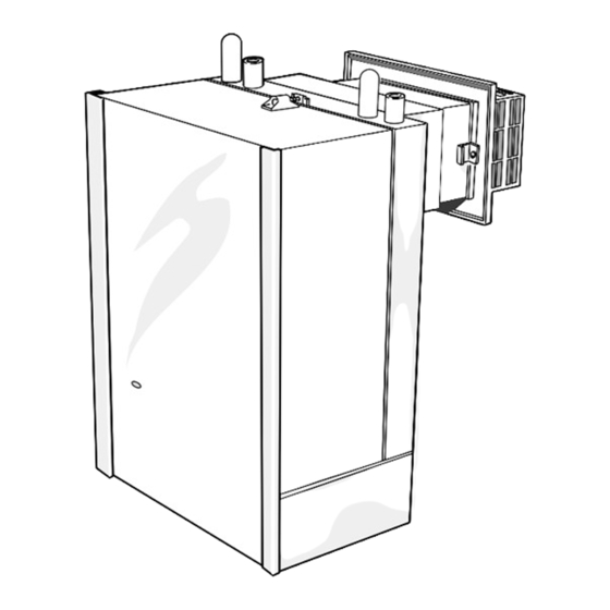
INSTALLATION 13 FITTING THE FLUE ASSEMBLY FLUE TERMINAL ASSEMBLY A. Air duct joint Legend 1.Boiler air duct. B. Flue duct joint 2.Boiler flue duct. 5.Terminal grille. 3.Terminal air duct. FLUE TERMINAL SHOWN IN POSITION 6.Terminal grille securing screws 4.Terminal flue duct. Note. -
Page 15: Electrical Connections
INSTALLATION 15 GAS CONNECTION 16 WATER CONNECTIONS A MINIMUM gas pressure of 20 mbar (8 in.w.g.) MUST be 1. Remove the plastic plugs from the flow and return available at the boiler inlet, with the boiler operating. pipes. The main gas cock is on the left hand side of the gas control valve, as shown. -
Page 16: System Diagrams
INSTALLATION 20 MID POSITION VALVE 21 TWO SPRING CLOSED VALVES Notes. Pumped only Notes. Pumped only 1. Some earth wires are omitted for clarity. Ensure proper earth 1. Some earth wires are omitted for clarity. Ensure proper earth continuity when wiring. continuity when wiring. -
Page 17: Initial Lighting
INSTALLATION 24 COMMISSIONING AND TESTING ELECTRICAL INSTALLATION GAS INSTALLATION 1. The whole of the gas installation, including the meter, 1. Checks to ensure electrical safety should be carried MUST be inspected and tested for soundness, and out by a competent person. purged in accordance with the recommendations of BS. -
Page 18: Fitting The Casing
INSTALLATION Deluxe Model (LX) Standard Model 26 FITTING THE CASING 1. Check that the sealing strip is in place along the 4 rear edges of the boiler casing. 2. Lift the boiler casing up to the boiler assembly, locate over the upper support bracket and secure with the 3 captive screws. -
Page 19: Servicing
SERVICING 29 SCHEDULE f. Check that the flue terminal is unobstructed and that the flue system is sealed correctly. To ensure the continued safe and efficient operation of the g. If the appliance has been installed in a compartment, check appliance, it is recommended that it is checked at regular that the ventilation areas are clear. -
Page 20: Cleaning The Flueways
SERVICING 32 CLEANING THE FLUEWAYS 33 CLEANING THE BURNER AND PILOT ASSEMBLY 1. Remove the collector hood by undoing the front tie rod nuts and releasing the tie rods from the combustion Refer to Frame 31 for illustration of the procedure below. chamber. -
Page 21: Replacement Of Parts
SERVICING REPLACEMENT OF PARTS 36 GENERAL When replacing any component: 1. Isolate the electricity supply. 2. Turn off the gas supply at the boiler - refer to the illustration below. Note. The gas cock is shown in the CLOSED position. 3. -
Page 22: Pilot Burner Replacement
SERVICING 39 PILOT BURNER REPLACEMENT 1. Refer to Frame 36. 5. Replace the pilot burner and retain 2. Remove burner and with the M4 screw air box assembly. previously Refer to Frame 31. removed. 3. Remove the 6. Replace the electrode retaining electrode and pilot nut. - Page 23 SERVICING 42 OVERHEAT THERMOSTAT REPLACEMENT 1. Refer to Frame 36. 2. Slacken the screw at the thermostat pocket and withdraw the phial from the pocket. 3. Unclip the capillary from the back panel. 4. Remove the control box fixing screw and pull the control box forward and downward to disengage.
-
Page 24: Gas Control Valve Replacement
SERVICING 46 GAS CONTROL VALVE REPLACEMENT Note. Refer also to Frame 54 'Exploded Views' for 1. Refer to Frame 36. illustration of the procedure detailed below. 2. Remove the burner support bracket, burner and air box assembly. Refer to Frame 31. 3. -
Page 25: Casing Seal Replacement
SERVICING 49 CASING SEAL REPLACEMENT 1. Refer to Frame 36. 2. Remove the old seal from the casing surround. 3. Thoroughly clean the casing surfaces and fit the adhesive seals. 4. Replace the boiler casing. Note. The standard model is illustrated here. Use the same procedure for the casing seal replacement on the deluxe model (LX) Inner view of boiler casing... -
Page 26: Fault Finding
FAULT FINDING Detailed instructions on the cleaning and adjustment or Before attempting any electrical fault finding ALWAYS carry replacement of faulty components are contained in the out preliminary electrical system checks, i.e. earth continuity, 'Servicing' section of this publication. polarity and resistance to earth using a suitable meter. 51 PILOT WILL NOT LIGHT Check the gap between the electrode and the pilot burner;... -
Page 27: Burner Assembly - Exploded View
SHORT LIST OF PARTS When ordering please quote: The following list is comprised of parts commonly required as replacement components, due to damage or expendability. Their 1. Boiler model failure or absence is likely to affect safety or performance. 2. Appliance G.C. number The list is extracted from the British Gas List of Parts, which 3. - Page 28 SHORT LIST OF PARTS 54 BOILER ASSEMBLY - Exploded view 28. Thermostat pocket 32. Wall mounting plate 33. Back panel 35. Balanced flue terminal 37. Programmer (optional) 39. Overheat thermostat (if fitted) LEGEND (Numbers up to 44 relate to the B.G. spares list) 15.
- Page 29 SHORT LIST OF PARTS 56 SHORT PARTS 57 BOILER CASING ASSEMBLY Standard Model Deluxe Model Classic LX, RS - Installation...
- Page 30 The code of practice for the installation, commissioning & servicing of central heating systems Technical Training LXFF.87/AQ/220 Natural Gas The Caradon Plumbing Limited Technical Training Centre LXRS.87/AQ/221 appliances are offers a series of first class training courses for domestic, service listed by commercial and industrial heating installers, engineers and FF.87/AP/107 British Gas...
- Page 31 YOUR FEEDBACK and your chance to win a free boiler At Ideal we've been leaders in the design and engineering of robust and reliable boilers for over 90 years. We want to continue as leaders by listening to your suggestions for how to improve our boilers and our service. We will be giving away a free boiler for the five best ideas every year (to be selected by our Technical Director).
-
Page 32: Further Information
Further information If you would like information about Ideal Boilers please complete this sheet and fax it to us on 01482 498699 or post it to Caradon Plumbing Limited, PO Box 103, National Avenue, Kingston upon Hull, HU5 4JN. Installer details...
Need help?
Do you have a question about the Classic LXRS 230 and is the answer not in the manual?
Questions and answers