Table of Contents
Advertisement
Advertisement
Chapters
Table of Contents

Subscribe to Our Youtube Channel
Related Manuals for Tait Orca 5000


Summary of Contents for Tait Orca 5000
- Page 1 Tait Orca 5000 Portable Radios Service Manual June 2003 IPN: M5000-00-105...
- Page 2 Preface Contacting Tait Electronics Ltd The contact details for your nearest Tait Electronics regional office, can be found on the Tait Website: http://www.taitworld.com/ Enquiries and comments If you have any enquiries regarding this manual, or any comments, suggestions and notifications of errors, please contact Customer Support, Tait Electronics Ltd, Christchurch, New Zealand, or refer to the Tait Website.
- Page 3 Publication history Publication Date Product Code May 2001 M5000-00-100 June 2001 M5000-00-101 September 2001 M5000-00-102 May 2002 M5000-00-103 September 2002 M5000-00-104 June 2003 M5000-00-105 June 2003 IPN: M5000-00-105...
- Page 4 June 2003 IPN: M5000-00-105...
-
Page 5: Table Of Contents
Calibration service kit .......................... A-3 Programming kit ..........................A-4 The Tait Orca 5000 series of portable radios The Tait Orca 5000 series of portable radios ................................ A-5 The Tait Orca 5000 series of portable radios The Tait Orca 5000 series of portable radios ................ - Page 6 TOP-Jxxxx 806-870MHz radio specifications..................B-11 TOP-Kxxxx 896-941MHz radio specifications ..................B-12 Circuit descriptions ......................... Circuit descriptions ......................... B-13 B-13 Circuit descriptions Circuit descriptions ..............................................B-13 B-13 Transmitter ............................B-13 Transmit (Tx) audio ........................... B-13 Receiver .............................. B-13 Receive (Rx) audio ..........................B-13 DSP ..............................
- Page 7 Replacing the LCD display (Orca 5015/2x/35/40) ................D-9 Replacing the shield, user interface PCB and polyester dome (Orca 5015/2x/35/40) ....... D-12 Replacing the antenna connector, channel selector switch and volume control switch ..... D-12 Replacing the microphone ......................... D-12 Replacing the battery and speaker contacts ..................D-12 Replacing the tact switch ........................
- Page 8 E-15 Multi-charger operation ........................E-15 Repairing the multi-charger ........................E-15 Fuse replacement ..........................E-16 Part F: Accessories Tait Orca 5000 accessory connector Tait Orca 5000 accessory connector ..................Tait Orca 5000 accessory connector Tait Orca 5000 accessory connector ....................................F-3 ..................Screw head types ...........................F-3 Connecting an accessory ........................F-3...
- Page 9 Introduction This part provides an introduction to servicing Tait Orca 5000 portable radios. It includes an outline of the Tait Orca 5000 range of products and precautions that should be taken before servicing Tait Orca 5000 portable radios. Detailed servicing instructions and information about spare parts are found in Part D: Servicing the radio.
- Page 10 IS PCB servicing requirements ................A-11 FM approval ......................A-11 FM approved products ..................A-11 FM approved accessories ..................A-11 A - 2 June 2003 IPN: M5000-00-105...
-
Page 11: Www Technical Support
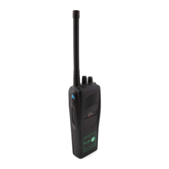
Servicing Tait Orca 5000 portable radios The Tait Orca 5000 series is a range of portable WWW technical support high performance, microprocessor-controlled Tait Electronics Ltd provides product support radios manufactured using an RF-shielded PCB at the following address: and high-density SMD components. -
Page 12: Programming Kit
I 9 pin RS232 to modular phone jack programming lead for connecting the programming cable to a PC (TOPA-SV- 019); and I TOP Programming Utilities (TPU) CD- ROM (IPN 406-00003-xx). A - 4 Servicing Tait Orca 5000 portable radios June 2003 IPN: M5000-00-105... -
Page 13: The Tait Orca Product Code
1. The complete Tait Orca product code The new chassis has a different shape hole for standard can be downloaded from the the connector’s quarter turn tip, and a green The Tait Orca 5000 series of portable radios A - 5 June 2003 IPN: M5000-00-105... - Page 14 To fit some accessories to the radio, you will portable radios. Figure A-3: Fitting an accessory with a D-Clip Figure A-4: Removing an accessory with a D-Clip A - 6 The Tait Orca 5000 series of portable radios June 2003 IPN: M5000-00-105...
- Page 15 1500 mAh NiMH battery pack TOPB500 2000 mAh NiMH battery pack TOPB600 1100 mAh NiCd battery pack (slim) TOPB700 1500 mAh NiMH battery pack (slim) The Tait Orca 5000 series of portable radios A - 7 June 2003 IPN: M5000-00-105...
- Page 16 These accessories only fit the older Table A-2: Tait Orca 5000 portable radio accessories with the old connector Type of accessory Product code Description Audio accessories TOPA-AA-001 Speaker microphone, -10 to 60°C, two function buttons...
-
Page 17: Basic Servicing Precautions
Standard anti-static procedures should be followed; a typical setup is shown in Figure A-5. Tait Orca 5000 portable radios require special- If in doubt, contact Tait Electronics Ltd or your ised servicing techniques and should only be nearest Tait dealer. -
Page 18: Calibrating
Calibrating Troubleshooting If you are experiencing difficulty operating For information on calibrating Tait Orca 5000 your Tait Orca portable radio check the follow- portable radios, refer to: ing items: I the Tait Orca Calibration Application User’s I Is the battery firmly attached to the radio? Manual or the online help. -
Page 19: Intrinsically Safe Radios
I TOP-x26x0-B2 hazardous locations. I TOP-x26x0-T2 Tait Orca 5000 IS portable radios can be For more information about the Tait Orca identified by one or more of the following: product code, refer to page page A-5. - Page 20 Table A-3: FM ratings Approval Class Division Group Temperature Rating Intrinsically Safe: Class I: Division 1: Groups C & D: T3C: The unit is unable to Gas or petroleum type Hazardous mixtures Ethylene and pro- 160°C cause ignition under environment. are normally present.
-
Page 21: Radio Specifications
Radio specifications and circuit descriptions This part outlines the radio specifications and circuit descriptions for Tait Orca portable radios. Contents Radio specifications ..................Radio specifications ..................B-3 Radio specifications Radio specifications .................................... General specifications .................... B-3 Receiver performance .................... B-3 Transmitter performance.................. - Page 22 B - 2 June 2003 IPN: M5000-00-105...
-
Page 23: Radio Specifications
Details of test methods and the conditions that 13 Ω Minimum load apply for type approval testing in all countries impedance can be obtained from Tait Electronics Ltd. Rated power 500 mW (1kHz, 60% deviation into 16 Ω) Important notes for Tables B-4 to B-11 Distortion <5% (1kHz, 60% deviation... -
Page 24: Transmitter Performance
Table B-3: Transmitter performance Parameter Performance Duty cycle (1 minute Tx, 4 minutes Rx at maximum temperature and voltage) ±50 µs (at mod audio out- Group delay variation put) bandwidth 300-3000 Hz Trunking data devia- tion (as per MPT1327) 1.5 kHz narrowband 2.4 kHz mediumband... -
Page 25: Top-Axxxx 66-88Mhz Radio Specifications
Table B-4: TOP-Axxxx 66-88MHz radio specifications General Orca 501x/2x Orca 503x/40 Frequency Range 66-88MHz Channel Spacing 12.5 / 20 / 25 kHz Frequency Increments 5 or 6.25kHz IF Bandwidth Universal Bandwidth (UB) 10kHz* Frequency Stability +/-15ppm (-20 to -10°C); +/-10ppm (-10 to +60°C) Current Consumption (Receiver Squelched) 80mA 100mA... -
Page 26: Top-Bxxxx 136-174Mhz Radio Specifications
Table B-5: TOP-Bxxxx 136-174MHz radio specifications General Orca 501x/2x Orca 503x/40 Frequency Range 136-174MHz Channel Spacing 12.5 / 20 / 25 kHz Frequency Increments 5 or 6.25kHz IF Bandwidth Universal Bandwidth (UB) 10kHz* Frequency Stability +/-2.5ppm (-30 to +60°C) Current Consumption (Receiver Squelched) 80mA 100mA Current Consumption (Standby with high economy duty... -
Page 27: Top-Cxxxx 174-225Mhz Radio Specifications
Table B-6: TOP-Cxxxx 174-225MHz radio specifications General Orca 501x/2x Orca 503x/40 Frequency Range 174-225MHz Channel Spacing 12.5 / 20 / 25 kHz Frequency Increments 5 or 6.25kHz IF Bandwidth Universal Bandwidth (UB) 10kHz* Frequency Stability +/-2.5ppm (-30 to +60°C) Current Consumption (Receiver Squelched) 80mA 100mA Current Consumption (Standby with high economy duty... -
Page 28: Top-Gxxxx 336-400Mhz Radio Specifications
Table B-7: TOP-Gxxxx 336-400MHz radio specifications General Orca 501x/2x Orca 503x/40 Frequency Range 336-400MHz Channel Spacing 12.5 / 20 / 25 kHz Frequency Increments 5 or 6.25kHz IF Bandwidth Universal Bandwidth (UB) 10kHz* Frequency Stability +/-2.5ppm (-30 to +60°C) Current Consumption (Receiver Squelched) 85mA 100mA Current Consumption (Standby with high economy duty... -
Page 29: Top-Hxxxx 400-470Mhz Radio Specifications
Table B-8: TOP-Hxxxx 400-470MHz radio specifications General Orca 501x/2x Orca 503x/40 Frequency Range 400-470MHz Channel Spacing 12.5 / 20 / 25 kHz Frequency Increments 5 or 6.25kHz IF Bandwidth Universal Bandwidth (UB) 10kHz* Frequency Stability +/-2.5ppm (-30 to +60°C) Current Consumption (Receiver Squelched) 80mA 100mA Current Consumption (Standby with high economy duty... -
Page 30: Top-Ixxxx 450-530Mhz Radio Specifications
Table B-9: TOP-Ixxxx 450-530MHz radio specifications General Orca 501x/2x Orca 503x/40 Frequency Range 450-530MHz Channel Spacing 12.5 / 20 / 25 kHz Frequency Increments 5 or 6.25kHz IF Bandwidth Universal Bandwidth (UB) 10kHz* Frequency Stability +/-2.5ppm (-30 to +60°C) Current Consumption (Receiver Squelched) 80mA 100mA Current Consumption (Standby with high economy duty... -
Page 31: Top-Jxxxx 806-870Mhz Radio Specifications
Table B-10: TOP-Jxxxx 806-870MHz radio specifications General Orca 501x/2x Orca 503x/40 Frequency Range 806-870MHz Transmit 851-870MHz Receive Channel Spacing 12.5 / 20 / 25 kHz Frequency Increments 5 or 6.25kHz IF Bandwidth Universal Bandwidth (UB) 10kHz* Frequency Stability +/-1.5ppm (-30 to +60°C) Current Consumption (Receiver Squelched) 85 mA 100mA... -
Page 32: Top-Kxxxx 896-941Mhz Radio Specifications
Table B-11: TOP-Kxxxx 896-941MHz radio specifications General Orca 501x/2x Orca 503x/40 Frequency Range 896-941MHz Transmit 935-941MHz Receive Channel Spacing 12.5 / 20 / 25 kHz Frequency Increments 5 or 6.25kHz IF Bandwidth Universal Bandwidth (UB) 10kHz* Frequency Stability +/-1.5ppm (-30 to +60°C) Current Consumption (Receiver Squelched) 85 mA 100mA... -
Page 33: Transmitter
Circuit descriptions Circuit interface diagrams for the Tait Orca Receiver portable radios are shown in Figure A-1 (TOP RF from the antenna is fed via the LPF and PIN B, C, G, H, I, J and K) and Figure A-2 (TOP A switch into the receiver. -
Page 34: Synthesiser And Vco
whose selection is controlled by a line from the Power supplies microprocessor. The speaker output is always available on the accessory connector to drive +5V-DIG an external speaker. The +5V-DIG supply provides a regulated 5 V to the microprocessor and its associated The unprocessed audio from the output of the circuitry. -
Page 35: Accessory Connector Interface
+4V3-DEC The +4V3-DEC supply is derived from the +5V-AN voltage. It is used to power the trans- mit and receive VCOs in conjunction with the transmit control line from the processor. It also provides the loop filter reference in the synthesiser. - Page 36 B - 16 Circuit descriptions June 2003 IPN: M5000-00-105...
- Page 41 Diagnostics and fault finding This part provides information on diagnosing faults in Tait Orca 5000 portable radios. The information in the fault finding charts should be used in combination with the test facilities, and it may also be helpful to...
- Page 42 C - 2 June 2003 IPN: M5000-00-105...
-
Page 43: Error Codes
Turn the radio off, then on again and put the radio into test mode. To put the radio into computer-controlled test If the error persists, contact your Tait dealer. mode, send ^ (Shift-6), wait for a return prompt (v), then immediately send % (Shift-5). - Page 44 Contact your Tait dealer. {X33} ESN error. The radio’s electronic serial number is incorrect. Contact your Tait dealer. {X35} Temperature is above the T1 threshold and turn down of transmit power is impending.
-
Page 45: Test Commands
Table C-1: Test commands Function Description CCTM code Parameters Signalling Set modem to send zeros None Set modem to send ones None Set modem to send preamble None Disable modem signalling None Read modem receive string (continuous) None Disable all signalling None Enable subaudible signalling None... - Page 46 Table C-1: Test commands (continued) Function Description CCTM code Parameters Radio info Read radio serial number 94/131 Returns: 6 digit number (hex) Read radio software version number Returns: 4 digit number Read radio type Returns: radio type (P or M), frequency band (B-J), channel spacing (1 or 2) Read DSP software version number...
-
Page 47: Calculating The Parameters Required For Test Command 101
Table C-2: Calculating the parameters required for test command 101 Calculating parameters for test command Example 1: Calculating tttttt for an H band radio Enter the parameters in the format tttttt T rrrrrr R F transmit frequency (MHz) tttttt = tttttt represents the transmit frequency channel spacing (MHz) See Example 1... -
Page 48: C - 8 Fault Finding Charts
The fault finding charts in Figures C-1 to C-6 If you experience other faults that do not fall address the faults you are most likely to find. into these categories, contact your Tait dealer. They are: I Radio cannot be switched on;... -
Page 49: Radio Cannot Be Switched On
After charging battery, can Replace battery contacts. radio be switched on? Check on/off/volume Replace on/off/volume control switch. control switch. Function for pins 1 to 4 OK? Return to nearest Tait Dealer Fault finding charts C - 9 June 2003 IPN: M5000-00-105... -
Page 50: Cannot Change Channel
Cannot change channel Using the truth table Replace channel below, is channel selector selector switch. operation OK? PINS Return to nearest Tait Dealer Antenna 1 = S/C to GND connector 16-way selector On/off/ 0 = O/C to GND volume control... -
Page 51: No Serial Communication
PCB. Is the flexible loom Replace flexible loom. end damaged? Is the PTT jammed on? Make sure PTT is released. Return to nearest Tait Dealer Fault finding charts C - 11 June 2003 IPN: M5000-00-105... -
Page 52: Receive Faults
Does on/off/volume pot vary Replace on/off/volume between 180 ohms to 10K control switch. between pin 3 and GND and between pin 2 and GND? Return to nearest Tait dealer C - 12 Fault finding charts June 2003 IPN: M5000-00-105... -
Page 53: Cannot Transmit
Is RF out assembly OK? power) or 700 mA (low power)? Is the transmit current Check PTT switch. Replace RF out assembly. less than 400 mA? Return to nearest Tait Dealer Fault finding charts C - 13 June 2003 IPN: M5000-00-105... -
Page 54: No Transmit Audio
Is the flexible loom damaged? Replace flexible loom. Is the internal Replace internal microphone. microphone working? Return to nearest Tait dealer C - 14 Fault finding charts June 2003 IPN: M5000-00-105... - Page 55 Servicing the radio This part describes the disassembly and reassembly of Tait Orca 5000 portable radios and the servicing of some key mechanical and ancillary devices. Information is also provided on ordering spare parts for servicing portable radios. Contents Servicing the radio Servicing the radio ..................
- Page 56 Reassembling the radio ................Reassembling the radio ................D-14 D-14 Reassembling the radio Reassembling the radio ................................D-14 D-14 Rear panel reassembly and replacing the auxiliary flexible PCB ......D-14 Fitting the PCB to the chassis and replacing the RF out assembly .......D-15 Fitting the shield to the chassis ................D-15 Fitting the front panel to the chassis ..............D-16 Spares kits ....................
-
Page 57: Screw Head Types
I the lens (Orca 5015/2x/35/40); Screw head types I the PTT keypad; Most of the screws in Tait Orca 5000 portable I the speaker; radios are Torx head screws, and so a Torx T6 driver bit is supplied as part of the service kit. -
Page 58: D - 4 Disassembling The Radio
Discard the knobs. chassis screws Some earlier Tait Orca 5000 portable radios have the knobs glued on. If so, the knob’s metal insert will remain on the switch shaft. Remove the insert using a sharp scalpel blade. -
Page 59: Removing The Shield Sub-Assembly From The Chassis
Figure D-3: Removing the front panel from the chassis, using the battery as leverage battery pack microphone grommet protruding from the shield front panel grip battery here, gently pull away from the front panel chassis pull radio out and away from the front panel at this point shield the chassis. -
Page 60: Removing The Pcb From The Chassis
Repeat this on the other side. Remove the At this point you can replace: microphone grommet by pulling upward I the main PCB assembly; (Figure D-5). I the antenna connector; You can now see the bottom surface of the I the channel selector switch; PCB. -
Page 61: Removing The Rear Panel
Removing the rear panel Follow the disassembly instructions and disas- semble the radio to the PCB level. Refer to Figure D-10 for the details of the rear panel assembly. Insert a small flat bladed screw driver under the auxiliary dummy rear cover and apply pressure to push the dummy rear cover lugs free of the holes in the rear panel. -
Page 62: D - 8 Replacing Key Mechanical And Ancillary Devices
Replacing key mechanical and ancillary devices This section describes the replacement of key Press firmly into position, then remove the mechanical and ancillary devices. These piece of clear plastic from the front of the lens. include: Figure D-6: Replacing the lens I lens (Orca 5015/2x/35/40);... -
Page 63: Replacing The Speaker
the hole at the top of the PTT recess. Be sure Replacing the LCD display (Orca not to split or otherwise damage it. 5015/2x/35/40) Following the disassembly instructions, remove Replacing the speaker the shield from the front panel and unplug the Following the disassembly instructions, user interface loom from the main PCB. - Page 64 Figure D-8: Bottom surface of the PCB, which is visible when the shield has been removed from the chassis antenna connector channel selector switch on/off/volume control switch antenna connector pin placement (5 pins) speaker contact pin placement channel selector pin placement (6 pins) on/off/volume control pin placement (5 pins)
- Page 65 Figure D-9: Top surface of PCB, which is visible only when the PCB has been removed from the chassis antenna connector channel selector switch on/off/volume control switch RF assembly placement auxiliary flex socket PTT tact pin placement (4 pins) battery contact placement battery contact seal placement microphone pin placement (2 pins) Replacing key mechanical and ancillary devices D - 11...
-
Page 66: Replacing The Shield, User Interface Pcb And Polyester Dome
edge of the PCB. Solder it in place using a light- Replacing the shield, user interface tip soldering iron (e.g. Weller PTR7 tip). PCB and polyester dome (Orca 5015/2x/35/40) Replacing the battery and speaker On Orca 5015/2x/35/40 radios the shield, user contacts interface PCB and polyester dome are replaced Following the disassembly instructions, disas-... -
Page 67: Replacing The Chassis
Replacing the chassis Following the disassembly instructions, fully disassemble the radio. Discard both the chassis and main seal. Inspect a new main seal to determine orienta- tion and top/bottom surfaces. The tab is locat- ed at the top of the radio. Note that the seal is not flat. -
Page 68: D - 14 Reassembling The Radio
Reassembling the radio This section describes the reassembly of the The rubber must sit flush with the back of the radio once the required units have been chassis or the rear panel will not sit properly serviced. Additional instructions for replacing and the battery will not fit correctly. -
Page 69: Fitting The Pcb To The Chassis And Replacing The Rf Out Assembly
socket driver set to 10in.lb (1.1Nm). Then Fitting the PCB to the chassis and tighten the PA screw to 2in.lb (0.23Nm). replacing the RF out assembly Using a heavy-tip soldering iron (e.g. Weller Put the battery contact seal over the battery 2PTCC8 tip), solder the antenna connector contacts rather than into the chassis. -
Page 70: Fitting The Front Panel To The Chassis
Figure D-12: Assembly of the switches shield chassis antenna connector channel selector switch on/off/volume control switch ribbed lock washer (M6x10x0.7 mm) SMA connector nut (¼x7.9x3 mm) channel/volume control nut (M6x7.9x3 mm) knob seal Fitting the front panel to the chassis Place the radio into the front panel top first, inserting the antenna connector and knob switches through the holes. -
Page 71: Spares Kits
The following table shows a list of spares kits PCB Product Codes which are currently available for servicing Tait Tait Orca 5000 main PCBs are available on an Orca 5000 portable radios. Spares kits are exchange basis from Technical Support at Tait designed to service 100 radios, and can be Electronics Ltd. -
Page 72: Orca 5010/11/30 Spares Kit (Topa-Sp-401G)
Table D-2: Orca 5010/11/30 spares kit (TOPA-SP-401G) Description Quantity Reference 040-05500-08 Volume Control Switch D-8 (3), D-9 (3) 219-50029-00 RF out assembly D-11 (1) 220-01414-03 Aux Flex Connector PCB D-10 (1) 231-00010-45 Channel Selector Switch D-8 (2), D-9 (2) 232-00010-42 Switch PTT (Low Profile) D-8 (8), D-9 (6) 240-02156-01... -
Page 73: Orca 5035 Spares Kit (Topa-Sp-402G)
Table D-3: Orca 5035 spares kit (TOPA-SP-402G) Description Quantity Reference 040-05500-08 Volume Control Switch D-8 (3), D-9 (3) 219-50029-xx RF out assembly D-11 (1) 220-01414-03 Aux Flex Connector PCB D-10 (1) 231-00010-45 Channel Selector Switch D-8 (2), D-9 (2) 232-00010-42 Switch PTT (Low Profile) D-8 (8), D-9 (6) 240-02156-01... -
Page 74: Orca 5015/2X/40 Spares Kit (Topa-Sp-403G)
Table D-4: Orca 5015/2x/40 spares kit (TOPA-SP-403G) Description Quantity Reference 008-36671-80 LCD Display — 040-05500-08 Volume Control Switch D-8 (3), D-9 (3) 219-50029-00 RF out assembly D-11 (1) 220-01414-03 Aux Flex Connector PCB D-10 (1) 231-00010-45 Channel Selector Switch D-8 (2), D-9 (2) 232-00010-41 Switch PTT (Low Profile) D-8 (8), D-9 (6) -
Page 75: Orca 5010/11/30 Re-Skinning Kit (Topa-Sp-404)
Table D-5: Orca 5010/11/30 re-skinning kit (TOPA-SP-404) Description Quantity 311-01049-01 Channel Knob 311-01050-01 Volume Knob 316-06765-00 Rear Panel 345-00020-11 Screw M2x8mm SS Pan Torx Patch 362-01106-00 Rear Cover Seal 362-01091-01 Knob Seal 362-01092-02 Main Seal OPP401 PHA Front Panel Assembly 399-00010-69 Plastic Bag 75x100mm Mini Grip 399-00010-53... -
Page 76: Orca 5015/2X/35/40 User Interface Pcb And Shield (Topa-Sp-407)
Table D-8: Orca 5015/2x/35/40 User Interface PCB and Shield (TOPA-SP-407) Description Quantity OPF200-B UI PCB SMT Subassembly 311-04005-00 Ins Poly Dome for 5015/2x/40 319-01026-00 Main Shield RF 399-00010-86 Static Shielding Bag 127x203mm 008-36671-80 LCD Display 12x2 Lines Flex 304-07043-00 LCD Frame Holder 220-01501-00 PCB Flexi User Interface 369-01044-00... - Page 77 Battery packs and chargers This part provides information on the battery packs and chargers available for Tait Orca 5000 portable radios. The battery packs are not serviceable, and repair of chargers is limited to replacement of the spring contacts, the discharge tact switch and the DC jack.
- Page 78 E - 2 June 2003 IPN: M5000-00-105...
-
Page 79: Battery Packs
Battery packs Six battery packs are available for Tait Orca to preserve the shift life of the battery: 5000 portable radios. These battery packs are I Charge or change the battery as soon as not serviceable, but their construction and the radio gives the ‘Low Battery’... -
Page 80: Disposing Of Used Nickel-Cadmium Batteries
I 40 mA with high economy cycling enabled. Economy cycling in conventional radios is programmed in the Power Save Features screen of the Tait Orca Portable Conventional Programming Application (TOPCPA). Dynamic power control in trunked radios is enabled in the User Selectable Parameters screen of the Tait Orca Portable Trunked Programming Application (TOPTPA). -
Page 81: Battery Chargers
Figure E-3. charging instructions for the fast charger also apply to the multi-charger. Table E-2: Contents of the Tait Orca chargers spares kit (TOPA-SP-202) Description Quantity For charger... -
Page 82: Fast Charger Operation
Desktop fast charger The Tait Orca desktop fast charger (Figure E-1) sor, D1, in conjunction with PolySwitch™ PS1. is an intelligent charger that can charge, condi- Under reverse polarity conditions, D1 tion and analyse both NiCd and NiMH batter- conducts, drawing the available short circuit ies of varying capacities. - Page 83 Desktop fast charger E - 7 June 2003 IPN: M5000-00-105...
- Page 84 The discharge circuit is based around a Software operation constant current sink. This uses an N-channel The charging sequence is as follows. MOSFET, Q6, controlled by an operational I Battery discharge (optional); amplifier, IC3:B. R41 and R42 are the current I Battery flat test;...
-
Page 85: Using The Fast Charger
recharging (5°C to 40°C). Using the fast charger Approximate charge times are: Fast charger indicators are described in Table E-3. I up to 1½ hours for TOPB100 and TOPB600; Table E-3: Fast charger indicators I up to 2 hours for TOPB200, TOPB400 and Indicator Meaning TOPB700;... -
Page 86: Repairing The Fast Charger
Release the condi- indicator will flash red if the battery is well tioning button. The LED will flash amber while below optimum capacity; consult your Tait the battery is being discharged. Once the dealer. battery is discharged, it will charge normally. - Page 87 Replacing the spring contacts Reassembling the charger Remove the faulty contacts with a soldering Refer to Figure E-3. iron and discard. Hold the body of the charger upside down and If the replacement spring contacts have a insert the conditioning button and the light larger diameter and will not fit through the pipe;...
-
Page 88: Desktop Trickle Charger
R104, which is set by Q102, its emitter resistors and the reference voltage. The Figure E-5: Tait Orca desktop trickle charger current slope of the curve is determined by Q101 and charge profile R106. The reference voltage is provided by an 8.2 V Zener diode (D100). -
Page 89: Using The Trickle Charger
Figure E-6: Circuit diagram of the Tait Orca desktop trickle charger = 12-18 VDC from T952-0X2 plug pack (12 VDC @ 1 A) Dropout voltage = 11.5 V until you next need to use the radio. However, Using the trickle charger... -
Page 90: Troubleshooting
I Check that the battery and charger contacts are clean and not obstructed. I May indicate a more serious fault such as a faulty battery. Contact your Tait dealer. The battery contacts show corrosion. I Contact corrosion may start to be noticed later in life, and will reduce battery cell capacity. -
Page 91: Multi-Charger Operation
Each multi- as that of the desktop fast charger. charger PCB has an additional diode. Figure E-7: The Tait Orca six-way multi-charger I Gently pull the faulty charger away from Repairing the multi-charger the multi-charger top. Turn the charger... -
Page 92: Fuse Replacement
I Fasten the charger to the multi-charger top using the three screws. I Reconnect the red and black wire to the Figure E-8: The Tait Orca Fast Charger PCB. fuse connector. Ensure that the polarity is The inset shows where to place the diode (1N4001 correct. - Page 93 Detailed servicing information about the Tait Orca vehicle kit is also provided on page F-10. A list of audio accessories currently available for use with Tait Orca 5000 portable radios is found in Table A-1, on page A-7. Contents Tait Orca 5000 accessory connector ...............
- Page 94 F - 2 June 2003 IPN: M5000-00-105...
-
Page 95: Tait Orca 5000 Accessory Connector
Tait Orca 5000 accessory connector The Tait Orca 5000 portable radio has a versa- P-Clip connector, and a Hex 2 driver for the D- tile accessory interface on the rear of the radio Clip connector. Additionally a Torx T6 driver for connecting external accessories, such as is required. - Page 96 (0.34Nm). accessory PCB, complete with pins PCB seal screw M2x5 Pan Torx quarter turn tip (lugs) screw M3x16 Pan Pozi (green P-Clip) screw M3x20 Hex (with D-Clip) F - 4 Tait Orca 5000 accessory connector June 2003 IPN: M5000-00-105...
-
Page 97: Connecting A Headset
Determine the compatibility/suitability of SPEAKER– your headset by checking Table F-1. If it is compatible, follow the assembly procedure SPEAKER+ outlined previously, on page F-4. Tait Orca 5000 accessory connector F - 5 June 2003 IPN: M5000-00-105... -
Page 98: Accessory Connector Signal Descriptions
On trunked radios, SENSE-1-ACC is a currently requiring RF, such as the RF speaker micro- unused input. phone. When an RF accessory is connected, the main antenna is switched out. F - 6 Tait Orca 5000 accessory connector June 2003 IPN: M5000-00-105... - Page 99 Figure F-3: Tait Orca accessory connector circuit diagram Tait Orca 5000 accessory connector F - 7 June 2003 IPN: M5000-00-105...
-
Page 100: 7.5 Mm Accessory Adaptor
7.5 mm Accessory adaptor You can connect non-Tait accessories that two separate lines for the Tait Orca portable require a 7.5 mm adaptor to the Tait Orca radio. The adaptor also detects the presence of portable radio using the 7.5 mm accessory the accessory speaker and turns off the radio’s... - Page 101 Figure F-5: Tait Orca 7.5 mm accessory adaptor circuit diagram 7.5 mm Accessory adaptor F - 9 June 2003 IPN: M5000-00-105...
-
Page 102: Tait Orca Vehicle Kit
Tait Orca vehicle kit The Tait Orca vehicle kit provides a secure Product Description environment for a Tait Orca portable radio code used in a vehicle. The vehicle kit allows the TOPA-VK-010 Vehicle kit mounting adaptor radio to be connected to the vehicle’s external... - Page 103 I the radio’s microphone will be inoperative The vehicle charger functional indicators are and an external microphone such as a summarised in Table F-4. Tait Orca vehicle kit F - 11 June 2003 IPN: M5000-00-105...
-
Page 104: Vehicle Kit Specifications
Fast charger charge cur- 0.8 A rent Charger control the charger uses voltage, tem- perature and temperature change to safely charge and maintain battery capacity F - 12 Tait Orca vehicle kit June 2003 IPN: M5000-00-105... -
Page 105: Servicing The Vehicle Kit
PCB; the PCB does not trigger assembly together. The trigger assem- require any force to insert. bly can now be lifted out. Note that the trigger assembly must be pressed Tait Orca vehicle kit F - 13 June 2003 IPN: M5000-00-105... -
Page 106: Spares Kits
Note that the ‘IPN’ column is the ten digit replace the trigger assembly. ‘internal part number’ which uniquely identi- fies any component used in a Tait product. While holding the trigger assembly cover togeth- er (before doing up the screws) check that the The numbers in the ‘Legend’... -
Page 107: Vehicle Kit Spares Kit (Topa-Sp-301)
Packaging - unprinted carton — * The green quarter turn moulding is compatible with both the old and new radio chassis. See “Update to the vehicle kit” on page F-10. Tait Orca vehicle kit F - 15 June 2003 IPN: M5000-00-105... -
Page 108: Vehicle Kit Reskinning Kit (Topa-Sp-302)
399-00010-53 Plastic bag 150 x 250mm — 399-00010-69 Mini grip plastic bag 75 x 100mm — 410-01153-00 Pkg Carton SII unprinted — 937-00000-79 Blazer label 60 x 25.4mm — F - 16 Tait Orca vehicle kit June 2003 IPN: M5000-00-105... -
Page 109: Custom Modifications
See “Tait Orca 5000 accessory connector” on down. You must unclip the microphone before page F-3 for further details about accessory a call can be initiated. - Page 110 Balanced output from audio PA SPKR- Balanced output from audio PA – – – – LVSD Low voltage shut down - turns off vehicle kit +13V8FILT 13.8V power 500 mA maximum F - 18 Tait Orca vehicle kit June 2003 IPN: M5000-00-105...
-
Page 111: Vehicle Kit Circuit Descriptions
PCB is shown in Figure F-9. The following subsections and their associated diagrams expand on the functionality of each vehicle kit PCB. Figure F-10: Vehicle kit accessory probe PCB block diagram Tait Orca vehicle kit F - 19 June 2003 IPN: M5000-00-105... - Page 112 1.3 V, the control- ler turns on Q9. Current source The switch mode current source is based around a Maxim MAX1627 100% duty cycle, Figure F-12: Vehicle kit charger PCB block diagram F - 20 Tait Orca vehicle kit June 2003 IPN: M5000-00-105...
- Page 113 IC3 pin 16. The the charger PCB is used to power down expanded voltage input used for fine voltage sections of the vehicle kit under various condi- Tait Orca vehicle kit F - 21 June 2003 IPN: M5000-00-105...
- Page 114 1 V above the threshold before the vehicle kit will be powered up. Figure F-13: Vehicle kit options PCB block diagram Note that to adjust the LVSD threshold, voltage F - 22 Tait Orca vehicle kit June 2003 IPN: M5000-00-105...
- Page 115 The 7V5-ACC signal is accessory power from microphone. In the vehicle kit this is accom- the radio and indicates if the radio is switched plished by R28, which is connected to the EXT- Tait Orca vehicle kit F - 23 June 2003 IPN: M5000-00-105...
- Page 116 RXD and TXD signals. These signals are converted to full RS-232 voltage levels (i.e. +10 V for a logic 0, and -10 V for a logic 1) by IC3. F - 24 Tait Orca vehicle kit June 2003 IPN: M5000-00-105...
-
Page 117: Additional Information
Additional information This part provides a glossary of terms. Contents Glossary ......................Glossary ......................G-3 Glossary Glossary ..........................................Accessory connector compatibility ............... Accessory connector compatibility ............... G-8 Accessory connector compatibility Accessory connector compatibility .......................... - Page 118 G - 2 June 2003 IPN: M5000-00-105...
- Page 119 Glossary Note: Note: Note: Note: Terms that appear in italics are also sending commands down a serial link to the defined in this glossary. radio. active channel The ‘on’ (asserted) state of a signal or indica- A receive/transmit frequency pair. tor.
- Page 120 When the radio is cycling between the receive mode and standby state. Available on Tait Orca conventional radios. Digital to analog converter. An electronic device that outputs a voltage dependent upon External call request.
- Page 121 G-STAR number General Electric status and reporting system. A simple string that corresponds to an Signaling is used to identify individual radio MPT1343 defined called party identifier. users by assigning a unique number to each P-Clip radio. This is sent out each time the radio transmits, and is decoded by the dispatcher, Accessory connector (without protruding ‘D’...
- Page 122 programming mode selecting The mode of operation of the radio in which The act of picking a label from a displayed list computer equipment can read from and write using the arrow keys. to the radio database. signalling PSTN Non-voice coding on the channel for the Public switched telephone network.
- Page 123 Also known as Type 99. In-band, two tone sequential signaling used to control the muting of a radio. Used for selective calling of individual units or groups of units. Tait Orca radios are able to decode Two-tone individual, group and super group calls.
- Page 124 Accessory connector compatibility Attempting to use an incompatible accessory the old and new accessory connectors with the connector with a particular chassis will result various chassis. in damage to both the radio and connector. How to identify a P-Clip, Green P-Clip or D- See “New chassis”...
- Page 125 Notes G - 9 June 2003 IPN: M5000-00-105...
Need help?
Do you have a question about the Orca 5000 and is the answer not in the manual?
Questions and answers