Helmer i.Series Service Manual
Undercounter refrigerator i.series and horizon series;
Hide thumbs
Also See for i.Series:
- Service manual (126 pages) ,
- Service and maintenance manual (76 pages) ,
- Operation manual (35 pages)
Table of Contents
Advertisement
Quick Links
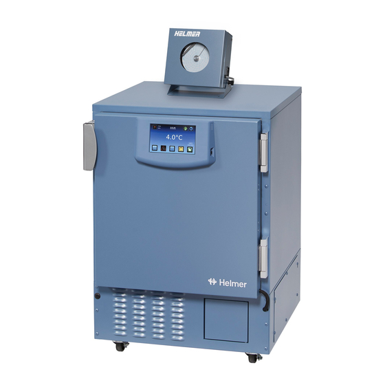
Undercounter Refrigerator Service Manual
i.Series
and Horizon Series™
®
HELMER SCIENTIFIC
14400 Bergen Boulevard
Noblesville, IN 46060 USA
PH +1.317.773.9073
FAX +1.317.773.9082
USA and Canada 800.743.5637
360117-1/E
Model Group
Blood Bank
iB105 (Version A)
Laboratory/Pharmacy
iLR105 (Version A)
i.Series
Horizon Series
HB105 (Version A)
HLR105 (Version A)
0086
ISO 13485:2003 CERTIFIED
Advertisement
Table of Contents
Troubleshooting

Subscribe to Our Youtube Channel
Related Manuals for Helmer i.Series


Summary of Contents for Helmer i.Series
- Page 1 Undercounter Refrigerator Service Manual i.Series and Horizon Series™ ® Model Group i.Series Horizon Series Blood Bank iB105 (Version A) HB105 (Version A) Laboratory/Pharmacy iLR105 (Version A) HLR105 (Version A) HELMER SCIENTIFIC 14400 Bergen Boulevard Noblesville, IN 46060 USA PH +1.317.773.9073 0086 FAX +1.317.773.9082...
- Page 2 Document History Revision Date Supersession Revision Description Supersedes A, 16 JAN 2014* 8580 Revised layout for ease of navigation and locating information. B, C, D * Date submitted for Change Order review. Actual release date may vary. 360117-1/E...
-
Page 3: Table Of Contents
Control System ........ - Page 4 Reverse Door Hinge and Handle ............17 7.8.1 Remove the Door and Hinges .
- Page 5 13.1 i.Series Schematic........
- Page 6 16 Settings ..............71 16.1 Monitor and Controller Interface .
-
Page 7: Section I: General Information
, i.Center ® , Horizon Series™, and Rel.i™ are registered trademarks or trademarks of Helmer, Inc. in the United States of America. Copyright © 2014 Helmer, Inc. All other trademarks and registered trademarks are the property of their respective owners. Helmer, Inc., doing business as (DBA) Helmer Scientific and Helmer. -
Page 8: Avoiding Injury
► Proceed with caution when adding and removing samples from the refrigerator. ► Use supplied power cord only. ► Using the equipment in a manner not specified by Helmer Scientific may impair the protection provided by the equipment. ► Decontaminate parts prior to sending for service or repair. Contact Helmer Scientific or your distributor for decontamination instructions and a Return Authorization Number. -
Page 9: Control System
General Information Control System NOTE Service information varies depending on the control system. Helmer refrigerators have one of two control systems installed. The type of control system varies by model. 3.2.1 i.Series Control System i.Series refrigerators are equipped with the i.Center monitoring system and independent temperature controller. -
Page 10: Temperature Probes
General Information Temperature Probes Number and location of probes varies by model. External probes may be introduced through existing rear port and immersed in existing probe bottle. For each probe bottle, use: ► Approximately 4 oz. (120 mL) of product simulation solution (10:1 ratio of water to glycerin). Left: Probe bottle with temperature probe. -
Page 11: Chart Recorder Access
General Information 3.4.1 Chart Recorder Access Open door by pulling door open. 3.4.2 Install Chart Paper Press and hold C button. When stylus begins to move left, release button. The LED flashes to indicate current temperature range. When stylus stops moving, remove chart knob then move knob up and away. Place chart paper on chart recorder. Gently lift stylus and rotate paper so current time line corresponds to time line groove. -
Page 12: Alarm Reference
The table indicates if an alarm is audible (A), visual (V), or sent through the remote alarm interface (R). Alarm Alarm Type High Temperature A, V, R Low Temperature A, V, R Compressor Temperature A, V, R (i.Series) Door Open (Time) A, V, R Power Failure A, V, R Low Battery V (i.Series) No Battery A, V, R (i.Series) -
Page 13: Warranty
► Horizon Series model compressor warranty period is five (5) years. 6.1.3 Parts For a period of two (2) years, Helmer will supply at no charge, including freight, any part that fails due to defects in material or workmanship under normal use, with the exception of expendable items. Expendable items such as glass, filters, light bulbs, and door gaskets are excluded from this warranty coverage. Inspection of defective parts by Helmer will be final in determining warranty status. Warranty... -
Page 14: Outside Of Usa And Canada
LIMITATION DAMAGES RELATED TO LOST REVENUES OR PROFITS, OR LOSS OF PRODUCTS. This warranty does not cover damages caused in transit, during installation by accident, misuse, fire, flood, or acts of God. Further, this warranty will not be valid if Helmer determines that the failure was caused by a lack of performing recommended equipment maintenance (per Helmer manual) or by using the product in a manner other than for its intended use. -
Page 15: Section Ii: I.series Models
Models Section II: i.Series Models ® Product Configuration Install Battery for Backup Power The monitoring system and chart recorder each have a battery system, enabling a period of continuous operation if power is lost. NOTE The monitoring system will not start on battery power alone. If the refrigerator was previously not connected to AC power and the batteries are installed, the monitoring system will not run on battery power. -
Page 16: Connect To Remote Alarm Interface
Models Terminals are dry contacts and do not supply voltage. Interface circuit is either normally open or normally closed, depending on terminals used. Requirements for your alarm system determine which alarm wires must connect to terminals. The terminals on the remote alarm interface have the following maximum load capacity: ► 0.5 A at 125 V (AC): 1 A at 250 V (DC) -
Page 17: Drawer Labels
Level the Refrigerator NOTE ► Leveling feet are optional. ► Helmer recommends the use of leveling feet. ► A bubble level may be used to ensure the refrigerator is level. Leveling feet must be adjusted to provide unit cooler drainage. -
Page 18: Optional Adapter Kits For Medication Dispensing Locks
Side-to-side: Rotate the leveling feet to raise or lower leveling feet. When refrigerator is properly leveled, bottom of the unit cooler will be horizontal (parallel to the floor). Optional Adapter Kits for Medication Dispensing Locks Contact Helmer Technical Service or your distributor for service documentation pertaining to medication dispensing locks. Reverse Door Hinge and Handle NOTICE Before reversing door hinge and handle, protect stored items in refrigerator from extended exposure to adverse temperature. - Page 19 Models Remove door latch / door catch. Remove two screws holding the door latch plates and spacer bar on the cabinet. Set the latch plates and spacer bar aside. Cabinet Strike plate Remove 2 screws Door latch plate. With the door shut, remove the cover plate from both hinges.
-
Page 20: Reinstall The Door And Hinges
Models Door Cabinet Hinge Remove 2 Remove 3 screws (long) screws (short) Shim Hinge plate Hinge removal (lower hinge shown with spring removed). Lay the door face-down in front of the cabinet. 7.8.2 Reinstall the Door and Hinges Install the hinges and hinge plates on the door. - Page 21 Tighten all screws attaching both hinges to the door and to the cabinet. NOTE If a shim is necessary to level the door after hinge reversal, contact Helmer Technical Service to obtain a shim. Install the door handle on the opposite side of the door.
-
Page 22: Stacked Undercounter Units
► When stacking a refrigerator and freezer (104 and/or 105 models), place the heavier unit on the bottom. ► Do not open multiple, loaded drawers or baskets at the same time. Call Helmer or your distributor for more information on the stacking kit, and for methods to secure both units to the wall and/or the floor. Temperature Monitor Settings... -
Page 23: Home Screen Functions
Models 8.1.1 Home Screen Functions NOTE Refer to chapter 14 (i.Center Screen Reference) for a complete list of screens in the i.Center monitoring system. ► View current temperature readings ► View the current time and date ► View detailed information about current or previous alarm events ► View the remaining backup battery charge... -
Page 24: Temperature Graph
► View the settings for temperature and time alarms ► View the software versions for control and display components of Product/Company Information the monitoring system ► View information to contact Helmer i.Help ► Access the on-board help system ► View historical event logs and details... -
Page 25: Change Configuration Password
Models Enable or disable the temperature graph: On the HOME screen, press the MAIN button. Press the DOWN button to select Edit Configuration. Press the SELECT button. Enter the password when prompted. Press the DOWN button to select Temperature Graph. Press the INC or DEC buttons to select enable or disable the temperature graph. -
Page 26: Factory Default Settings
Models Press the DOWN button to highlight Temperature Calibration. Press the SELECT button. The Upper Probe option is displayed and the Temperature option is highlighted. Press the INC or DEC buttons to change the displayed value to match the value measured by the independent thermometer. -
Page 27: Restore Factory Default Settings
Models Restore Factory Default Settings Restore settings: Press the MAIN button. Press the DOWN button to highlight Edit Configuration. Press the SELECT button. Enter the password when prompted. Press the DOWN button to highlight Factory Default Settings. Press the SELECT button. Do one of the following: ► Press the ENTER button. Factory default settings are restored. -
Page 28: High Chamber Temperature Alarm
► Default setpoint is 50 °C ► Setpoint can be changed from -40 °C to +80 °C NOTICE Condenser Temperature Alarm should not be changed unless directed by Helmer Technical Service. Change the setpoint: Press the MAIN button. -
Page 29: Door Ajar Alarm
Models Press the INC or DEC buttons to change the setting. Press the BACK button to return to the Edit Configuration screen, or press the HOME button to exit. The new settings are saved. 8.8.6 Door Ajar Alarm The Door Ajar Timeout specifies longest time the refrigerator door can be open before the alarm activates. If the time elapsed since the last door opening is greater than or equal to this value, the alarm activates. -
Page 30: Test Alarms
Models Press the DOWN button to highlight System Options. Press the SELECT button. Press the DOWN button to highlight Chart Paper Timer. Press the INC or DEC buttons to select Enabled, Disabled, or Reset. Do one of the following: ► If Enabled or Disabled is selected, press the BACK button to return to the System Options... -
Page 31: Manual Chamber Alarm Test
Models Press the DOWN button to select Start High Alarm Auto Test. Press the SELECT button. ► The “High Alarm Test in Progress” message appears. When the test is complete, the message clears. View the Event Log. Note the temperature at which the low alarm occurred. Compare the temperature to the high alarm setpoint. -
Page 32: Power Failure Alarm Test
Models Remove probe from warm water. Place temperature probe in probe bottle, immersing it at least 2” (50 mm). 8.9.3 Power Failure Alarm Test NOTE ► During a power failure, the power failure alarm sounds and the batteries provide power to the monitoring system. -
Page 33: Additional System Settings
Ensure the monitoring system backup batteries are installed. Remove one battery from the monitoring system backup battery holder. If the no battery alarm activates, no further action is needed. Reinstall the battery. If the no battery alarm does not activate, contact Helmer Technical Service. NOTICE When installing replacement batteries, use only batteries which meet the specifications outlined in chapter 10.7 (Supplies). -
Page 34: Temperature Units
Models Set the display language on power-on: Switch the AC ON/OFF switch ON. Install the monitoring system battery that is taped next to the backup battery holder. ► The refrigerator powers on and the i.Center will display the System Options screen. -
Page 35: Event Log
Models 8.11 Event Log The Event Log shows information from alarm events. ► 50 (most recent) events can be viewed on the Event Log screen. ► Number of door openings for the current and previous day can be viewed. -
Page 36: Event Details
Models 8.11.1 Event Details Event Log Detail screen. Label Description Event number Event Alarm Type Date and time of event Chamber temperature at time of event Condenser temperature at time of event View an event: Press the MAIN button. -
Page 37: View Manufacturer And Product Information
► Security (3) NOTICE Changing parameter values affects refrigerator operation. Do not change parameter values unless instructed in product documentation or by Helmer Technical Service. NOTE ► To change the value for a parameter, first enter the program mode for that level. ► When there is no interaction for 25 seconds, the temperature controller exits program mode and returns to normal mode. -
Page 38: Operational (Level 1) Parameters And Values (Ou)
Models Exit program mode: Press and hold the UP and DOWN arrow buttons simultaneously for approximately one second. The current chamber temperature is displayed. Operational (Level 1) Parameters and Values (OU) NOTE ► Parameters are listed in order of appearance. -
Page 39: Change The Refrigerator Setpoint
If the variance is within acceptable limits for your organization, changing the offset value is optional. Change the Hysteresis Value ► Default setpoint is 2.0 °C ► Allowable temperature variance on each side of the refrigerator setpoint NOTICE Hysteresis is factory-preset and should not be changed unless directed by Helmer Technical Service. 360117-1/E... -
Page 40: Maintenance
► Calibrated pressure gauge (0 psi to 25 psi (0 kPa to 175 kPa)) NOTICE If the compressor has been changed, the refrigerant charge amount may be different than stated above. if the compressor has been changed, contact Helmer Technical Service for to verify the refrigerant charge amount. Add refrigerant: Attach pressure gauge to the fittings on the refrigeration lines. -
Page 41: Replace Monitoring System Backup Batteries
Clean with soft cloth and mild soap and water solution. 10.5.5 Clean and Refill Probe Bottle NOTE A kit that includes a probe bottle and glycerin is available from Helmer. Obtain: ► Fresh water-bleach solution (not provided) ► 1:9 ratio of bleach to water ► Bleach is 5% solution of commercial sodium hypochlorite (NaOCl) -
Page 42: Unit Cooler Cover Removal And Installation
Models Clean and refill bottle: Remove probe from bottle. Remove bottle from bracket. Clean bottle with water-bleach solution. Fill bottle with 4 oz. (120 mL) of product simulation solution. Cap bottle tightly to minimize evaporation. Place bottle in bracket. Replace probe, immersing at least 2” (50 mm). -
Page 43: Install The Unit Cooler Cover
Models Remove the unit cooler cover. Hold unit cooler cover in place to prevent it from dropping. Use the socket wrench to remove four screws securing the unit cooler cover. Carefully lower unit cooler cover to avoid damage to the fan wiring. -
Page 44: Chamber Temperature Problems
Models Problem Possible Cause Action Door does not open Debris in the hinges. ► Confirm the hinges are free of debris. Clean the easily. hinges if necessary. A hinge is faulty. ► Confirm the hinge spring or pin is not damaged. Replace entire hinge (lower hinge only), if necessary. ► Replace the entire lower hinge spring and pin... -
Page 45: Alarm Activation Problems
Models Problem Possible Cause Action Chamber temperature Probe bottle is empty, ► Check the level of product simulation solution in does not stabilize or the amount of the bottle. Clean and refill the bottle if necessary. at the refrigerator solution is too low. setpoint. ► Check the condenser grill. Clean it if necessary. - Page 46 Models Problem Possible Cause Action Refrigerator meets an The alarm setpoint ► Check the current setpoints for the temperature alarm condition, but was changed. alarms. Change the setpoints if necessary. the appropriate alarm A component is ► Contact a qualified service technician. is not active.
- Page 47 ► Clean as necessary, or order new ones from Condenser alarm is Condenser fins are active. dirty. Helmer or your distributor. ► Check to ensure the refrigerator is placed Ambient temperature is too high. according to the operating specifications in the operation manual. Condenser fan motor ► Replace the condenser fan motor.
-
Page 48: Testing Problems
Models Problem Possible Cause Action An alarm activated, Monitor settings are ► Confirm the temperature probe is reading correctly. but the temperature not calibrated. Calibrate the probe if necessary. recorded at activation Temperature changed ► No action needed. does not match the slightly around the alarm setpoint. -
Page 49: Condensation Problems
Models 11.5 Condensation Problems Problem Possible Cause Action Excessive water in Humid air is entering ► Confirm the refrigerator is level, and the door the water evaporation the chamber is aligned, closing tightly, and sealing correctly. tray inside the lower Correct issues as necessary. compartment in the back of the unit. -
Page 50: Parts
Models Parts NOTICE ► Before replacing parts, protect items in refrigerator from extended exposure to adverse temperature. ► Allow refrigerator temperature to stabilize at setpoint after replacing parts or after extended door opening. 12.1 Front 12.1.1 Monitoring System Monitoring features. -
Page 51: I.center Display Parts
The i.Center display assembly is sensitive to static electricity and can be damaged by electrostatic discharge. Use proper ESD precautions when handling the display assembly. NOTE Although the LCD display and touchpad may be replaced individually, Helmer recommends replacing the entire display assembly. 360117-1/E... -
Page 52: Lower Panel
Models 12.1.3 Lower Panel Front panel features. Schematic Label Description Part Number Label Monitoring system backup batteries 715031 Flash port Circuit breakers (230 V models only; knockouts shown on 230 V / 50 Hz 120272 115 V model) 230 V / 60 Hz 120288... -
Page 53: Rear
Models 12.2 Rear Rear features. Schematic Label Description Part Number Label Nut flanges for brace bars used in stacking undercounter units (four shown) Rear access port Drain line (copper tube segment) 321190-1 Product specification label Power cord connector 120299 Compressor/component rear compartment door 321184-1 Remote alarm contacts i.Center monitoring system data port... -
Page 54: Electrical Tray
Models 12.2.1 Electrical Tray Kick plate (removed). Pull-out electrical components tray (open). WARNING Disconnect the refrigerator from AC power before accessing the electrical tray. NOTICE The control board is sensitive to static electricity and can be damaged by electrostatic discharge. -
Page 55: Interior
Models 12.3 Interior Interior features. Schematic Label Description Part Number Label Door Solid door Stainless steel: 400916-1 Powder coated: 400916-2 Glass door (optional) Stainless steel: 400917-1 Powder coated: 400917-2 Drawer (blood bank model) 400752-3 Door switch 120380 Roll-out basket (optional) -
Page 56: Lighting
Models 12.3.1 Lighting Light features (partial views). Schematic Label Description Part Number Label Light assembly (includes circuit board and cover) 800023-1 Light cover shown 12.3.2 Unit Cooler Left: Unit cooler with fan guard. Middle: Unit cooler fan. Right: Temperature control probe. -
Page 57: Door Hinges
Models 12.4 Door Hinges Hinge, hinge spring and pin assembly, and door handle with key lock. NOTE Spring tension is controlled at the point where the pin is stopped by the side plate (C, D). Label Description Part Number... -
Page 58: Side Access Panel
Models 12.5 Side Access Panel Undercounter refrigerators feature easy access for servicing, removal, and replacement of the compressor and condenser. The compressor is accessible from the rear and the side. Side access panel. 360117-1/E... -
Page 59: Schematics
Models Schematics 13.1 i.Series Schematic 360117-1/E... -
Page 60: 14 I.center Screen Reference
Models i.Center Screen Reference HOME screen MAIN button MAIN screen MUTE button (changes mute timer) LIGHT button (turns light on or off, if option installed) MAIN screen Event Log option (Press the SELECT button) EVENT LOG screen System Alarm Test & Status option SYSTEM ALARM TEST &... - Page 61 Models SYSTEM OPTIONS screen Language option Date Format option Alarm Volume option Alarm Pulse option Temperature Units option Chart Paper Timer option SET ALARM SETPOINT screen High Alarm Setpoint option Low Alarm Setpoint option Cond. Alarm Setpoint option Door Ajar Timeout option...
-
Page 62: Section Iii: Horizon Series™ Models
Horizon Series™ Models Section III: Horizon Series™ Models Product Configuration 15.1 Install Battery for Backup Power The monitoring system has a battery system, enabling a period of continuous operation if power is lost. NOTE The monitoring system will start on battery power alone. If the refrigerator was previously not connected to AC power and the battery is connected, the monitoring system will begin running on battery power. -
Page 63: Connect To Remote Alarm Interface
Horizon Series™ Models Terminals are dry contacts and do not supply voltage. Interface circuit is either normally open or normally closed, depending on terminals used. Requirements for your alarm system determine which alarm wires must connect to terminals. The terminals on the remote alarm interface have the following maximum load capacity: ► 0.5 A at 125 V (AC): 1 A at 250 V (DC) 15.2.1 Connect to Remote Alarm Interface... -
Page 64: Move Slides And Brackets
(toward the condensate drain line). Side-to-side: Rotate the leveling feet to raise or lower leveling feet. When refrigerator is properly leveled, bottom of the unit cooler will be horizontal (parallel to the floor). 15.6 Optional Adapter Kits for Medication Dispensing Locks Contact Helmer Technical Service or your distributor for service documentation pertaining to medication dispensing locks. 360117-1/E... -
Page 65: Reverse Door Hinge And Handle
Horizon Series™ Models 15.7 Reverse Door Hinge and Handle NOTICE Before reversing door hinge and handle, protect stored items in refrigerator from extended exposure to adverse temperature. NOTE Refrigerator must be on the floor or on an elevated work surface with enough space in front of the refrigerator to lay the door face-down for disassembly. 15.7.1 Remove the Door and Hinges Open the lower front control panel. - Page 66 Horizon Series™ Models Remove the door handle assembly. Remove four screws holding the door handle assembly on the door. Set the door handle assembly aside. Remove Door handle assembly. Remove door latch / door catch. Remove two screws holding the door latch plates and spacer bar on the cabinet Set the latch plates and spacer bar aside.
-
Page 67: Reverse The Cable Routing In The Door
Horizon Series™ Models 10 Remove the lower hinge. Support the door. Remove five screws attaching the lower hinge to the door and cabinet. Remove the lower hinge. Reverse the hinge manually (as if moving the hinge from a fully-closed to a fully-open position). Set the lower hinge aside. Continue to support the door. 11 Remove the upper hinge. - Page 68 Horizon Series™ Models Label Description Outer door frame Data cable (gray) Cable exit (corner of door) Additional cable slack Lay the door assembly face-down on a solid work surface. Remove remaining screws from both sides of the door assembly. Lift the inner door frame out of the outer door frame and set aside. A J-hook tool may be used along the bottom edge of the door assembly to lift the inner frame.
-
Page 69: Reinstall The Door And Hinges
Horizon Series™ Models Left: Original cable routing (right-hinged door). Right: New cable routing (left-hinged door). Route the data cable out of the door. Slide the data cable through the slot in the door. Insert the door-side grommet into the hole in the door. Reinstall the inner door frame inside the outer door frame. - Page 70 Tighten all screws attaching both hinges to the door and to the cabinet. NOTE If a shim is necessary to level the door after hinge reversal, contact Helmer Technical Service to obtain a shim. Route the data cable across the front of the cabinet. Attach the cable to the zip tie holder under the cabinet on the hinge side.
- Page 71 Horizon Series™ Models Washer Internal hex cap Spring Spring cap Bushing Use a J-hook tool in the spring cap to compress the spring upward (Figure C). While compressing the spring, slide the spring cap over the lower hex bolt in the lower hinge (Figure D).
-
Page 72: Stacked Undercounter Units
► When stacking a refrigerator and freezer (104 and/or 105 models), place the heavier unit on the bottom. ► Do not open multiple, loaded drawers or baskets at the same time. Call Helmer or your distributor for more information on the stacking kit, and for methods to secure both units to the wall and/or the floor. Settings Through the Horizon Series monitoring and control system, current settings may be viewed and changed. -
Page 73: Refrigerator Setpoint
Horizon Series™ Models Label Description Function DOWN ARROW / Decreases a temperature setting. Also mutes the audible alarm for MUTE ALARM button five minutes. SET button Allows settings to be selected, prior to changing settings. NOTE The Alarm Disable key switch disables all audible alarms. This switch does not affect alarm lamps or signals sent through the remote alarm interface. -
Page 74: High Temperature Alarm
Horizon Series™ Models Flashing Lamp Selected Setting HIGH TEMP and MONITOR High Temp alarm setpoint LOW TEMP and MONITOR Low Temp alarm setpoint MONITOR only Monitor Offset CONTROL only Control Sensor Offset CONTROL only Control Hysteresis 16.3.1 High Temperature Alarm ► Specifies the temperature at which the High Temperature Alarm activates. -
Page 75: Monitor Offset
Horizon Series™ Models Flashing Lamp Selected Setting MONITOR only Monitor Offset CONTROL only Control Sensor Offset CONTROL only Control Hysteresis 16.4.1 Monitor Offset ► Adjust if temperature displayed on the monitor does not match measured chamber temperature. ► Value is factory-set to match an independent thermometer. ► Value can be changed from -10.0 °C to +10.0 °C. -
Page 76: Control Sensor Offset
Hysteresis ► Default setpoint is 1.0 °C ► Allowable temperature variance on each side of the refrigerator setpoint. NOTICE Hysteresis is factory-preset and should not be changed unless directed by Helmer Technical Service. 16.5 Test Alarms Test alarms to ensure they are working correctly. The refrigerator has alarms for chamber temperature, power failure, and door open (time). -
Page 77: Power Failure Alarm
Horizon Series™ Models Compare the temperature at which the alarm sounds to the low alarm setpoint. If values do not match, refer to chapter 18 (Troubleshooting). Test the high alarm: Identify setting for high alarm setpoint. While stirring probe in chilled water, add warm water so temperature increases 0.5 °C per minute. When high temperature alarm sounds, note the temperature on the monitoring system display. -
Page 78: Maintenance
► Calibrated pressure gauge (0 psi to 25 psi (0 kPa to 175 kPa)) NOTICE If the compressor has been changed, the refrigerant charge amount may be different than stated above. if the compressor has been changed, contact Helmer Technical Service for to verify the refrigerant charge amount. Add refrigerant: Attach pressure gauge to the fittings on the refrigeration lines. -
Page 79: Replace Led Lamp Strip (Optional)
Clean with soft cloth and mild soap and water solution. 17.4.5 Clean and Refill Probe Bottle NOTE A kit that includes a probe bottle and glycerin is available from Helmer. Obtain: ► Fresh water-bleach solution (not provided) ► 1:9 ratio of bleach to water ► Bleach is 5% solution of commercial sodium hypochlorite (NaOCl) -
Page 80: Unit Cooler Cover Removal And Installation
Horizon Series™ Models Place bottle in bracket. Replace probe, immersing at least 2” (50 mm). 17.5 Unit Cooler Cover Removal and Installation If unit cooler cover is not removed as detailed in this procedure the drain port may be damaged. Improper drainage may result in excessive icing and refrigerator’s inability to maintain temperature. -
Page 81: Supplies
Horizon Series™ Models Attach unit cooler cover. Lift unit cooler cover into place. Front edge of the cover should be behind the unit cooler case. Use the socket wrench to install four screws to secure the unit cooler cover. Insert the drain hose through hole in the refrigerator. Push drain hose upward, toward the unit cooler drain port. -
Page 82: Troubleshooting
Horizon Series™ Models Troubleshooting CAUTION ► Review all safety instructions prior to troubleshooting. Refer to chapter 2 (Safety). ► Troubleshooting should only be performed by trained refrigeration technicians. 18.1 General Operation Problems Problem Possible Cause Action A drawer or basket Debris in the drawer ► Pull the drawer or basket out and confirm the does not slide easily. -
Page 83: Alarm Activation Problems
Horizon Series™ Models Problem Possible Cause Action Chamber temperature Monitor/control board ► Confirm the monitor/control board is operating does not stabilize is faulty. correctly. Replace it if necessary. at the refrigerator Condensing unit fan is ► Check the condensing unit fan connections. setpoint. not running. Replace the fan motor if necessary. - Page 84 Horizon Series™ Models Problem Possible Cause Action Refrigerator meets an Monitor/control board ► Replace the monitor/control board. alarm condition, but is faulty. the appropriate alarm Alarm setpoint was ► Check the current setpoints for the temperature is not active. changed. alarms.
-
Page 85: Condensation Problems
Horizon Series™ Models Problem Possible Cause Action Door Open alarm is Door is not closing ► Clean hinges if debris is present. ► Confirm door is aligned. activating sporadically. completely. ► Confirm hinge spring and/or pin are not damaged. Replace hinge (lower only) if necessary. Door is closing but not ► Confirm the door gasket seals completely. - Page 86 Horizon Series™ Models Problem Possible Cause Action Excessive moisture on Humid air is entering ► Confirm the refrigerator is level, and the door is the doors. the chamber. aligned, closing tightly, and sealing correctly. Relative humidity ► Confirm refrigerator location meets requirements. around refrigerator is too high. ► Confirm the refrigerator is level, and the door is Water leaks from Humid air is entering the bottom of the the chamber.
-
Page 87: Parts
Horizon Series™ Models Parts NOTICE ► Before replacing parts, protect items in refrigerator from extended exposure to adverse temperature. ► Allow refrigerator temperature to stabilize at setpoint after replacing parts or after extended door opening. 19.1 Front 19.1.1 Control System Display Top: Horizon Series combined controller and monitor. -
Page 88: Control And Monitoring
Horizon Series™ Models 19.1.2 Control and Monitoring Label Description Part Number Schematic Label Horizon Series monitoring and control system Temperature chart recorder (standard on blood bank model, optional on laboratory / pharmacy model) Chart paper (52 sheets) 220366 Chart recorder backup battery 120218 shown 19.1.3... -
Page 89: Rear
Power cord connector 120299 Compressor/component rear compartment door 321184-1 Remote alarm contacts Power cord Condensate evaporator tray Compressor Contact Helmer Condensing unit fan motor Contact Helmer Compressor solid state relay 400842-1 shown Defrost timer 800120-1 Caster (optional, swivel with brake) -
Page 90: Electrical Tray
Horizon Series™ Models 19.2.1 Electrical Tray Kick plate (removed). Pull-out electrical components tray (open). WARNING Disconnect the refrigerator from AC power before accessing the electrical tray. NOTICE The control board is sensitive to static electricity and can be damaged by electrostatic discharge. -
Page 91: Interior
Horizon Series™ Models 19.3 Interior Interior features. Schematic Label Description Part Number Label Door Solid door Stainless steel: 400918-1 Powder coated: 400918-2 Glass door (optional) Stainless steel: 400919-1 Powder coated: 400919-2 Drawer (blood bank model) 400752-4 Door switch 120380 Roll-out basket (optional) 400815-1 Standard for shelf, drawer, or roll out basket 321173-1... -
Page 92: Lighting (Optional)
Horizon Series™ Models 19.3.1 Lighting (Optional) Light features (partial views). Schematic Label Description Part Number Label Light assembly (includes circuit board and cover) 800023-1 Light cover shown 19.3.2 Unit Cooler Left: Unit cooler with fan guard. Middle: Unit cooler fan. Right: Temperature control probe. Schematic Label Description... -
Page 93: Door Hinges
Horizon Series™ Models 19.4 Door Hinges Hinge, hinge spring and pin assembly, and door handle with key lock. NOTE Spring tension is controlled at the point where the pin is stopped by the side plate (C, D). Label Description Part Number Hinge, covered, edge mount 220506 Hinge, uncovered, without spring assembly... -
Page 94: Side Access Panel
Horizon Series™ Models 19.5 Side Access Panel Undercounter refrigerators feature easy access for servicing, removal, and replacement of the compressor and condenser. The compressor is accessible from the rear and the side. Side access panel. 360117-1/E... -
Page 95: Schematics
Horizon Series™ Models Schematics 20.1 Horizon Series Schematic END OF MANUAL 360117-1/E... - Page 96 HELMER SCIENTIFIC 14400 Bergen Boulevard Noblesville, IN 46060 USA PH +1.317.773.9073 FAX +1.317.773.9082 www.helmerinc.com...
Need help?
Do you have a question about the i.Series and is the answer not in the manual?
Questions and answers