Honda EU10i Owner's Manual
Honda eu10i generator owner's manual
Hide thumbs
Also See for EU10i:
- Owner's manual (262 pages) ,
- Fitting and operating instructions (4 pages) ,
- Owner's manual (58 pages)
Table of Contents
Advertisement
Advertisement
Table of Contents

Related Manuals for Honda EU10i


Summary of Contents for Honda EU10i
- Page 2 06/03/23 10:38:53 32ZT3604_001 Honda EU10i OWNER’S MANUAL MANUEL DE L’UTILISATEUR BEDIENUNGSANLEITUNG MANUAL DE EXPLICACIONES...
- Page 3 06/03/23 10:38:55 32ZT3604_002...
- Page 4 06/03/23 10:39:00 32ZT3604_003 Honda EU10i OWNER’S MANUAL The‘‘e-SPEC’’mark symbolizes environmentally responsible technologies applied to Honda power equipment, which contains our wish to ‘‘preserve nature for generations to come.’’...
- Page 5 06/03/23 10:39:01 32ZT3604_004...
- Page 6 All information in this publication is based on the latest product information available at the time of approval for printing. Honda Motor Co., Ltd. reserves the right to make changes at any time without notice and without incurring any obligation.
-
Page 7: Table Of Contents
Carburetor Modification for High Altitude Operation GENERATOR USE ................22 STOPPING THE ENGINE ..............34 MAINTENANCE ................36 TRANSPORTING/STORAGE ............43 TROUBLESHOOTING ............... 45 SPECIFICATIONS ................47 WIRING DIAGRAM ................49 MAJOR Honda DISTRIBUTOR ADDRESSES ........ . 54... -
Page 8: Safety Instructions
06/03/23 10:39:27 32ZT3604_007 SAFETY INSTRUCTIONS To ensure safe operation Honda generator is designed to give safe and dependable service if operated according to instructions. Read and understand the Owner’s Manual before operating the generator. Failure to do so could result in personal injury or equipment damage. - Page 9 06/03/23 10:39:40 32ZT3604_008 To ensure safe operation Gasoline is extremely flammable and explosive under certain conditions. Refuel in a well ventilated area with the engine stopped. Keep away from cigarette, smoke and sparks when refueling the generator. Always refuel in a well-ventilated location. Wipe up spilled gasoline at once.
- Page 10 06/03/23 10:39:48 32ZT3604_009 To ensure safe operation Always make a pre-operation inspection (page ) before you start the engine. You may prevent an accident or equipment damage. Place the generator at least 1 m (3 ft) away from buildings or other equipment during operation.
-
Page 11: Safety Label Locations
Read the labels and safety notes and precautions described in this manual carefully. If a label comes off or becomes hard to read, contact your Honda dealer for a replacement. [For European model: G, GW, B, F, W types]... - Page 12 06/03/23 10:40:21 32ZT3604_011 SOCKET CAUTION [For Australian model: U type]...
-
Page 13: Ce Mark And Noise Label Locations
06/03/23 10:40:28 32ZT3604_012 CE mark and noise label locations [For European model: G, GW, B, F, W types] NOISE LABEL CE MARK Manufacturer and address Maximum ambient temperature Performance class IP code Maximum altitude Dry weight... -
Page 14: Component Identification
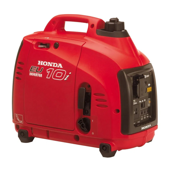
06/03/23 10:40:35 32ZT3604_013 COMPONENT IDENTIFICATION FUEL CAP VENT LEVER CHOKE LEVER FUEL FILLER CAP CONTROL PANEL LEFT SIDE MAINTENANCE COVER STARTER GRIP ENGINE SWITCH FRAME SERIAL NUMBER SPARK PLUG MAINTENANCE COVER MUFFLER Record the frame serial number in the space below. You will need this serial number when ordering parts. -
Page 15: Control Panel
06/03/23 10:40:39 32ZT3604_014 CONTROL PANEL G, GW, F, W types AC RECEPTACLE PARALLEL OPERATION SOCKETS ECO THROTTLE SWITCH GROUND TERMINAL OIL ALERT INDICATOR LIGHT OVERLOAD INDICATOR LIGHT OUTPUT INDICATOR LIGHT DC RECEPTACLE DC CIRCUIT PROTECTOR... - Page 16 06/03/23 10:40:43 32ZT3604_015 B type AC RECEPTACLE U type AC RECEPTACLE...
- Page 17 06/03/23 10:40:52 32ZT3604_016 Eco Throttle ECO: Engine speed is kept at idle automatically when the electrical appliance is disconnected and it returns to the proper speed by the electrical load when electrical appliance is connected. This position is recommended to minimize the fuel consumption while in operation. Eco Throttle system does not operate sufficiently if the electrical appliance requires the momentary electric power.
-
Page 18: Pre-Operation Check
06/03/23 10:41:00 32ZT3604_017 PRE-OPERATION CHECK Be sure to check the generator on a level surface with the engine stopped. Check the engine oil level. Using nondetergent oil or 2-stroke engine oil could shorten the engine’s service life. Use high-detergent, premium quality 4-stroke engine oil, certified to meet or exceed U.S. - Page 19 06/03/23 10:41:07 32ZT3604_018 Loosen the cover screw and remove the left side maintenance cover. (see page Remove the oil filler cap, and wipe the dipstick with a clean rag. Check the oil level by inserting the dipstick in the filler hole without screwing it in.
- Page 20 06/03/23 10:41:18 32ZT3604_019 Check the fuel level. If the fuel level is low, refuel the fuel tank until the level as specified. After refueling, tighten the fuel filler cap securely. Use automotive unleaded gasoline with a Research Octane Number of 91 or higher (a Pump Octane Number of 86 or higher).
- Page 21 Gasolines containing alcohol If you decide to use a gasoline containing alcohol (gasohol), be sure it’s octane rating is at least as high as that recommended by Honda. There are two types of ‘‘gasohol’’: one containing ethanol, and the other containing methanol.
- Page 22 06/03/23 10:41:39 32ZT3604_021 Check the air cleaner. Check the air cleaner element to be sure it is clean and in good condition. Loosen the cover screw and remove the left side maintenance cover. Press the latch tab on the top of the air cleaner body, remove the air cleaner cover, check the element.
-
Page 23: Starting The Engine
06/03/23 10:41:47 32ZT3604_022 STARTING THE ENGINE Before starting the engine disconnect any load from the AC receptacle. Turn the fuel cap lever fully clockwise to the ON position. Turn the fuel cap vent lever to the OFF position when transporting the generator. - Page 24 06/03/23 10:41:54 32ZT3604_023 Move the choke lever to the CLOSED position. Do not use the choke when the engine is warm or the air temperature is high. CHOKE LEVER CLOSED CLOSED Pull the starter grip lightly until you feel resistance, then pull the starter grip briskly toward the arrow as shown below.
- Page 25 06/03/23 10:41:58 32ZT3604_024 Move the choke lever to the OPEN position as the engine warms up. CHOKE LEVER OPEN If the engine stops and will not restart, check the engine oil level (see page ) before troubleshooting in other areas.
-
Page 26: Carburetor Modification For High Altitude Operation
High altitude performance can be improved by specific modifications to the carburetor. If you always operate your generator at altitudes above 1,500 meters (5,000 feet), have your authorized Honda servicing dealer perform this carburetor modification. This engine, when operated at high altitude with the carburetor modifications for high altitude use, will meet each emission standard throughout its useful life. -
Page 27: Generator Use
06/03/23 10:42:20 32ZT3604_026 GENERATOR USE Be sure to ground the generator when the connected equipment is grounded. Connections for standby power to a building’s electrical system must be made by a qualified electrician and must comply with all applicable laws and electrical codes. Improper connections can allow electrical current from the generator to backfeed into the utility lines. - Page 28 06/03/23 10:42:24 32ZT3604_027 The DC receptacle can be used while the AC power is in use. If you use both at the same time, be sure not to exceed the total power for AC and DC. (See page Most appliance motors require more than their rated wattage for startup.
- Page 29 06/03/23 10:42:32 32ZT3604_028 AC applications Start the engine and make sure the Output indicator (green) comes Confirm that the appliance to be used is switched off, and plug in the appliance. PLUG OUTPUT INDICATOR OVERLOAD INDICATOR LIGHT (GREEN) LIGHT (RED) Substantial overloading that continuously lights the overload indicator light (red) may damage the generator.
- Page 30 When an electric motor is started, both the Overload indicator (red) and the Output indicator (green) may go on simultaneously. This is normal if the Overload indicator (red) goes off after about five (5) seconds. If the Overload indicator (red) stays on, consult your Honda generator dealer.
- Page 31 Please read the item ‘‘GENERATOR USE’’ before connecting any equipment to be used. A max output of 2.0 kVA can be obtained by using two units (EU10i) in parallel operation (connection in parallel). There are the terminals into which the special cable is inserted for parallel operation.
- Page 32 06/03/23 10:43:01 32ZT3604_031 Never connect the different generator models and types. Never connect a cable other than the special cable for parallel operation. Connect and remove the special cable for parallel operation with the engine stopped. For single operation, the special cable for parallel operation must be removed.
- Page 33 06/03/23 10:43:09 32ZT3604_032 Be sure to ground the generator when the connected equipment is grounded. GROUND TERMINAL GROUND TERMINAL Start each engine according to ‘‘STARTING THE ENGINE’’. When the output indicator light (green) does not light and the overload indicator light (red) lights instead, set the engine switch to STOP, stop the engine once, and then start the engine again.
- Page 34 06/03/23 10:43:15 32ZT3604_033 Switch on the equipment to be used. The output indicator light (green) will light. In case of normal operation In case of overload operation or short-circuit OVERLOAD INDICATOR LIGHT OUTPUT INDICATOR LIGHT (RED) (GREEN) In case of overload operation (refer to page ) or when trouble occurs for the equipment being used, the output indicator light (green) will go out, the overload indicator light (red) will light...
- Page 35 06/03/23 10:43:20 32ZT3604_034 When equipment requiring a large starting power, like a motor etc., is used, the overload indicator light (red) and the output indicator light (green) may light together for a short time (about 4 sec), but this is no abnormality. After start of the equipment, the overload indicator light (red) will go out and the output indicator light (green) will stay lit.
- Page 36 06/03/23 10:43:28 32ZT3604_035 DC Application The DC receptacle may be used for charging 12 volt automotive-type batteries only. In DC operation, turn the eco throttle switch to the OFF position. Connect the charging cable to the DC receptacle of the generator and then to the battery terminals.
- Page 37 06/03/23 10:43:43 32ZT3604_036 Batteries produce explosive gases: If ignited, and explosion can cause serious injury or blindness. Provide adequate ventilation when charging. CHEMICAL HAZARD: Battery electrolyte contains sulfuric acid. Contact with eyes or skin, even through clothing, may cause severe burns.
- Page 38 06/03/23 10:43:48 32ZT3604_037 Oil alert system The Oil Alert system is designed to prevent engine damage caused by an insufficient amount of oil in the crankcase. Before the oil level in the crankcase falls below a safe limit, the Oil Alert system will automatically shut down the engine (the engine switch will remain in the ON position).
-
Page 39: Stopping The Engine
06/03/23 10:43:56 32ZT3604_038 STOPPING THE ENGINE To stop the engine in an emergency, turn the engine switch to the OFF position. IN NORMAL USE: Switch off the connected equipment and pull the inserted plug. PLUG Turn the engine switch to the OFF position. ENGINE SWITCH... - Page 40 06/03/23 10:44:02 32ZT3604_039 Turn the fuel cap vent lever fully counterclockwise to the ‘‘OFF’’ position. FUEL CAP VENT LEVER Be sure the fuel cap vent lever and the engine switch are ‘‘OFF’’ when stopping, transporting and/or storing the generator. When parallel operation has been executed, pull the special cable for parallel operation.
-
Page 41: Maintenance
Service more frequently when used in dusty areas. These items should be serviced by your servicing dealer, unless you have the proper tools and are mechanically proficient. Refer to Honda shop manual for service procedures. For commercial use, log hours of operation to determine proper maintenance... - Page 42 06/03/23 10:44:30 32ZT3604_041 CHANGING OIL Drain the oil while the engine is still warm to assure rapid and complete draining. Make sure to turn the engine switch and the fuel cap vent lever OFF before draining. Loosen the cover screw and remove the left side maintenance cover. Remove the oil filler cap.
- Page 43 06/03/23 10:44:41 32ZT3604_042 AIR CLEANER SERVICE A dirty air cleaner will restrict air flow to the carburetor. To prevent carburetor malfunction, service the air cleaner regularly. Service more frequently when operating the generator in extremely dusty areas. Do not use gasoline or low flash point solvents for cleaning. They are flammable and explosive under certain conditions.
- Page 44 06/03/23 10:44:50 32ZT3604_043 SPARK PLUG SERVICE RECOMMENDED SPARK PLUG: CR4HSB (NGK) U14FSR-UB (DENSO) To ensure proper engine operation, the spark plug must be properly gapped and free of deposits. Remove the spark plug maintenance cover. SPARK PLUG MAINTENANCE COVER Remove the spark plug cap. Clean any dirt from around the spark plug base.
- Page 45 06/03/23 10:45:00 32ZT3604_044 Visually inspect the spark plug. Discard it if the insulator is cracked or chipped. Clean the spark plug with a wire brush if it is to be reused. Measure the plug gap with a feeler gauge. Correct as necessary by carefully bending the side electrode. The gap should be: 0.60 0.70 mm (0.024 0.028 in) 0.60 0.70 mm...
- Page 46 06/03/23 10:45:08 32ZT3604_045 SPARK ARRESTER MAINTENANCE (Equipped type) If the generator has been running, the muffler will be very hot. Allow it to cool before proceeding. The spark arrester must be serviced every 100 hours to maintain its efficiency. Remove the four 5 mm screws, and remove the muffler protector. MUFFLER PROTECTOR 5 mm SCREW Remove the three 6 mm bolts, and remove the muffler, the spark...
- Page 47 06/03/23 10:45:13 32ZT3604_046 Use a brush to remove carbon deposits from the spark arrester screen. Inspect the spark arrester screen for holes or tears. Replace if necessary. Check the muffler gasket; replace if damaged. Reinstall the muffler gasket, the spark arrester, the muffler and the muffler protector in the reverse order of removal.
-
Page 48: Transporting/Storage
06/03/23 10:45:25 32ZT3604_047 TRANSPORTING/STORAGE To prevent fuel spillage when transporting or during temporary storage, the generator should be secured upright in its normal operating position, with the engine switch OFF. The fuel cap vent lever is turned fully counterclockwise to the ‘‘OFF’’ position. - Page 49 06/03/23 10:45:34 32ZT3604_048 Turn the engine switch ON, and loosen the carburetor drain screw and drain the gasoline from the carburetor into a suitable container. With the drain screw loosened remove the spark plug cap, and pull the starter grip 3 to 4 times to drain the gasoline from the fuel pump. Turn the engine switch to the OFF position, and tighten the drain screw securely.
-
Page 50: Troubleshooting
Add the in the engine? recommended oil. Is the spark plug Clean, readjust in good gap and dry the condition? spark plug. Replace it if necessary. If the engine still does not start, take the generator to an authorized Honda dealer. - Page 51 06/03/23 10:45:54 32ZT3604_050 Appliance does not operate: Is the Output indicator ON? Take the Is the Overload generator to an indicator ON? authorized Honda dealer. Check the Take the electrical NO DEFECTS generator to an appliance or authorized equipment for Honda dealer.
-
Page 52: Specifications
06/03/23 10:46:07 32ZT3604_051 SPECIFICATIONS Dimensions and Weight Model EU10i Description code EZGA Length 450 mm (17.7 in) Width 240 mm (9.4 in) Height 380 mm (15.0 in) Dry weight 13 kg (29 lbs) Engine Model GXH50 Engine type 4-stroke, overhead valve, single cylinder Displacement 50 cm (3.1 cu-in) - Page 53 06/03/23 10:46:18 32ZT3604_052 Generator Model EU10i Type G, GW, B, F, W Rated voltage (V) Rated frequency (Hz) output Rated Ampere (A) Rated Output (VA) Max Output (VA) 1,000 Only for charging 12 V DC rated output automotive batteries. 12 V, 8 A...
-
Page 54: Wiring Diagram
06/03/23 10:46:23 32ZT3604_053 WIRING DIAGRAM AC, NF AC Noise Filter ACOR AC Output Receptacle Capacitor Composite Socket Control Panel Block DC, D DC Diode DC, NF DC Noise Filter DCOR DC Output Receptacle DC, W DC Winding EcoSw Eco throttle switch Engine Block Engine Ground Engine Switch... - Page 55 06/03/23 10:46:27 32ZT3604_054 BLACK YELLOW BLUE GREEN WHITE BROWN LIGHT GREEN GRAY LIGHT BLUE ORANGE PINK ENGINE SWITCH ECOTHROTTLE SWITCH...
- Page 56 06/03/23 10:46:36 32ZT3604_055 G, GW, B, F, W type...
- Page 57 06/03/23 10:46:44 32ZT3604_056 U type...
- Page 58 06/03/23 10:46:54 32ZT3604_057 RECEPTACLE Shape Type G, GW...
-
Page 59: Major Honda Distributor Addresses
Honda Power Equipment Sweden AB Västkustvägen 17 Tel: 040-600 23 00 202 15 Malmö, Fax: 040-600 23 19 Sweden Honda Produtos De Força, Portugal, S.A. Lugar da Abrunheira Tel: 351-1-9150374 S. Pedro de Penaferrim Fax: 351-1-9111021 2710 Sintra, Portugal Berema A/S... - Page 60 2040 Buda-rs, Kamaraerdei-t 3. Tel: 23-444-971 Hungary Fax: 23-444-972 For Australian NAME OF FIRM (COMPANY) ADDRESS TEL: FAX: Honda Australia Motorcycle and Power 1954-1956 Hume Highway Tel: (03) 9270 1111 Equipment Pty. Ltd Campbelifield Victoria 3061 Fax: (03) 9270 1133...
- Page 61 06/03/23 10:47:48 32ZT3604_060...
Need help?
Do you have a question about the EU10i and is the answer not in the manual?
Questions and answers