ABB FENA-01 User Manual
Ethernet adapter module
Hide thumbs
Also See for FENA-01:
- User manual (100 pages) ,
- Protocol manual (52 pages) ,
- Hardware manual (24 pages)

Related Manuals for ABB FENA-01


Summary of Contents for ABB FENA-01
- Page 1 Options for ABB drives, converters and inverters User’s manual FENA-01/-11/-21 Ethernet adapter module...
-
Page 2: List Of Related Manuals
9AKK105408A7004 ACS880-04 manuals 9AKK105713A4819 ACS880-07 manuals 9AKK105408A8149 Option manuals and guides FENA-01/-11/-21 Ethernet 3AUA0000093568 adapter module user’s manual You can find manuals and other product documents in PDF format on the Internet. See section Document library on the Internet on the inside of the back cover. - Page 3 User’s manual FENA-01/-11/-21 Ethernet adapter module Table of contents 1. Safety instructions 4. Mechanical installation 5. Electrical installation Modbus/TCP protocol EtherNet/IP protocol PROFINET IO protocol 3AUA0000093568 Rev B 2014 ABB Oy All Rights Reserved. EFFECTIVE: 2014-01-29...
-
Page 5: Table Of Contents
Example topology of the Ethernet link ....34 FENA-01/-11/-21 Ethernet adapter module ....35... - Page 6 Parameter setting examples – ACS355 ....64 Speed and torque control using the ABB Drives – Enhanced communication profile ....64 Starting up fieldbus communication for ACSM1 drives .
-
Page 7: Table Of Contents
Communication profiles ....... 85 ABB Drives communication profile ..... . . 87 Control word and Status word . - Page 8 Communication profiles ....... 98 ABB Drives profile - Classic ......99 ABB Drives profile - Enhanced .
-
Page 9: Table Of Contents
Table of contents 9 Speed control using the ODVA AC/DC drive profile, Extended speed control assembly ....142 Starting up fieldbus communication for ACS880 and ACS580 drives . - Page 10 Torque Actual (AC/DC drive object) ....171 ABB Drives communication profile ..... . 172 Control word and Status word .
-
Page 11: Table Of Contents
Class attributes ......227 Instance #1: FENA-01/-11/-21 configuration parameters group A (group 1) ......227 Instance #2: FENA-01/-11/-21 configuration parameters group B (group 2) . - Page 12 PPO Type 4 ......264 Speed and torque control using the ABB Drives communication profile with PPO Type 4... . 266 Starting up fieldbus communication for ACSM1 drives .
- Page 13 Downloading the GSD file ......289 Configuring an ABB AC500 PLC ....289 Configuring a Siemens SIMATIC S7 PLC .
- Page 14 Actual values in positioning mode (ACSM1 only)..315 ABB Drives communication profile ..... . 316 Control word and Status word ..... . 316 Control word contents.
- Page 15 Contents of this chapter ......361 FENA-01/-11/-21 ........361 Ethernet link .
- Page 16 Product training ........387 Providing feedback on ABB Drives manuals ....387...
-
Page 17: Safety Instructions
Safety instructions 17 Safety instructions Contents of this chapter The chapter contains the warning symbols used in this manual and the safety instructions which you must obey when you install or connect an optional module to a drive, converter or inverter. If you ignore the safety instructions, injury, death or damage can occur. -
Page 18: Use Of Warnings
18 Safety instructions Use of warnings Warnings tell you about conditions which can cause injury or death, or damage to the equipment. They also tell you how to prevent the danger. The manual uses these warning symbols: Electricity warning tells you about hazards from electricity which can cause injury or death, or damage to the equipment. -
Page 19: Safety In Installation
Safety instructions 19 Safety in installation These instructions are for all who install or connect an optional module to a drive, converter or inverter and need to open its front cover or door to do the work. WARNING! Obey these instructions. If you ignore them, injury or death, or damage to the equipment can occur. - Page 20 20 Safety instructions...
-
Page 21: Introduction To The Manual
Introduction to the manual 21 Introduction to the manual Contents of this chapter This chapter introduces this manual. Applicability This manual applies to the FENA-01/-11/-21 Ethernet adapter module, SW version 3.00 and later. Compatibility Drives This table shows the compatibility of the FENA adapter module with the different ABB drives. -
Page 22: Protocols
SW version 0.290 onwards. Modbus/TCP EtherNet/IP™ PROFINET IO FENA-01 FENA-11 FENA-21 In addition to Modbus/TCP, FENA-01/-11/-21 supports Modbus over UDP. This table specifies the clients/masters that are compatible with the supported protocols. Protocol Compatible client/master Modbus/TCP All Modbus/TCP clients that support: •... -
Page 23: Tools
You are expected to know the fundamentals of electricity, wiring, electrical components and electrical schematic symbols. The manual is written for readers worldwide. Both SI and imperial units are shown. Purpose of the manual The manual provides information on installing, commissioning and using the FENA-01/-11/-21 Ethernet adapter module. -
Page 24: Contents
Safety instructions gives the safety instructions which you must obey when you install a fieldbus adapter module. • Overview of the Ethernet network and the FENA-01/-11/-21 module contains a short description of the Ethernet network and the adapter module. •... - Page 25 Introduction to the manual 25 EtherNet/IP protocol • EtherNet/IP – Start-up presents the steps to take during the start-up of the drive with the adapter module and gives examples of configuring the EtherNet/IP client. • EtherNet/IP – Communication profiles describes the communication profiles used in the communication between the client, the adapter module and the drive.
-
Page 26: Terms And Abbreviations
(sometimes called the Command word). FENA-01/-11/-21 One of the optional fieldbus adapter modules Ethernet adapter available for ABB drives. FENA-01/-11/-21 is a module device through which an ABB drive is connected to an Ethernet network. Fieldbus adapter... -
Page 27: Modbus/Tcp Terms And Abbreviations
Introduction to the manual 27 Abbreviation Explanation DHCP Dynamic Host Control Protocol. A protocol for automating the configuration of IP devices. DHCP can be used to automatically assign IP addresses and related network information. Electromagnetic compatibility Fieldbus adapter Least significant bit Most significant bit Programmable logic controller ... -
Page 28: Profinet Io Terms And Abbreviations
ODVA stands for Open DeviceNet Vendor Association. ODVA is an independent organization that promotes interoperativity between different manufacturers’ EtherNet/IP products. ABB is an Associate Member at ODVA. Output In the ODVA EtherNet/IP specification the word ‘output’ is used to describe data flow from the network into a device (such as the adapter module). - Page 29 Introduction to the manual 29 Term Explanation GSD file ASCII-format device description file in a specified form. Each different slave type on the PROFINET IO network needs to have its own GSD file. GSD files in PROFINET IO are written in GSDML.
- Page 30 30 Introduction to the manual The text in italics is the original German term. Abbreviation Explanation Actual value Istwert Device access point Decentralised Periphery Dezentrale Peripherie DP-V0 PROFINET IO extension to the EN 50170 standard, providing the basic functionality of DP, including cyclic data exchange DP-V1 PROFINET IO extension to the EN 50170...
- Page 31 Introduction to the manual 31 Abbreviation Explanation Reference Sollwert Control word Steuerwort Status word Zustandswort...
- Page 32 32 Introduction to the manual...
-
Page 33: Overview Of The Ethernet Network And The Fena-01/-11/-21 Module 33
Overview of the Ethernet network and the FENA-01/-11/-21 module 33 Overview of the Ethernet network and the FENA-01/-11/- 21 module Contents of this chapter This chapter contains a short description of the Ethernet network and the FENA adapter module. Ethernet network Ethernet standards support a variety of physical media (coaxial cable, twisted pair, fiber optics) and topologies (bus and star). -
Page 34: Example Topology Of The Ethernet Link
34 Overview of the Ethernet network and the FENA-01/-11/-21 module Example topology of the Ethernet link This figure shows an example of an allowable topology for an Ethernet network with FENA-01/-11. ABB drive Other slave Other slave device device... -
Page 35: Fena-01/-11/-21 Ethernet Adapter Module
Overview of the Ethernet network and the FENA-01/-11/-21 module 35 FENA-01/-11/-21 Ethernet adapter module The FENA-01/-11/-21 Ethernet adapter module is an optional device for ABB drives which enables the connection of the drive to an Ethernet network. Through the adapter module you can: •... -
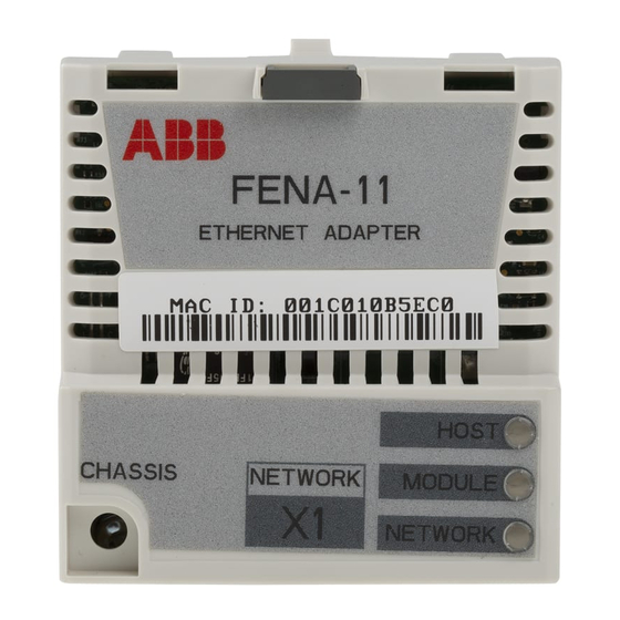
Page 36: Layout Of The Adapter Module
36 Overview of the Ethernet network and the FENA-01/-11/-21 module Layout of the adapter module This figure shows the layout of FENA-01/-11. Description See chapter Lock Mechanical installation Mounting screw Mechanical installation Connector X1 to Ethernet Electrical installation Diagnostic LEDs Modbus/TCP –... - Page 37 Overview of the Ethernet network and the FENA-01/-11/-21 module 37 This figure shows the layout of FENA-21. Description See chapter Lock Mechanical installation Mounting screw Mechanical installation Connector X1 to Ethernet Electrical installation Connector X2 for chaining Electrical installation another adapter module Diagnostic LEDs Modbus/TCP –...
- Page 38 38 Overview of the Ethernet network and the FENA-01/-11/-21 module...
-
Page 39: Mechanical Installation
See the applicable drive hardware manual. Unpacking and examining the delivery 1. Open the option package. 2. Make sure that the package contains: • Ethernet adapter module, type FENA-01/-11/-21 • this manual. 3. Make sure that there are no signs of damage. -
Page 40: Installing The Adapter Module
40 Mechanical installation Installing the adapter module WARNING! Obey the safety instructions. See chapter Safety instructions on page 17. If you ignore the safety instructions, injury or death can occur. The adapter module has a specific position in the drive. Plastic pins, a lock and one screw hold the adapter module in place. - Page 41 Mechanical installation 41 2. Put the adapter module carefully into its position on the drive. 3. Push in the lock. 4. Tighten the screw. Note: It is necessary to tighten the screw properly to fulfill the EMC requirements and to ensure the proper operation of the module.
- Page 42 42 Mechanical installation...
-
Page 43: Electrical Installation
Electrical installation 43 Electrical installation Contents of this chapter This chapter contains: • general cabling instructions • instructions on connecting the adapter module to the Ethernet network. Warnings WARNING! Obey the safety instructions. See chapter Safety instructions on page 17. If you ignore the safety instructions, injury or death can occur. -
Page 44: General Cabling Instructions
STP. When CAT5 FTP or STP is used, the cable shield is connected to the drive frame through an RC network. In FENA-01, it is possible to change this connection by using jumper J1 located next to the X1 connector. -
Page 45: Connection Procedure
Electrical installation 45 Connection procedure 1. Connect the network cable to the RJ-45 connector (X1) on the adapter module. 2. If you want to create a daisy chain with FENA-21 adapter modules, connect the X2 connector of the first adapter module to X1 on the next adapter module, and so on. - Page 46 46 Electrical installation...
-
Page 47: Modbus/Tcp Protocol
Modbus/TCP protocol Modbus/TCP – Start-up ....... Modbus/TCP – Communication profiles . -
Page 49: Modbus/Tcp - Start-Up
Modbus/TCP – Start-up 49 Modbus/TCP – Start-up Contents of this chapter This chapter contains: • information on configuring the drive for operation with the adapter module • drive-specific instructions on starting up the drive with the adapter module • information on configuring the client for communication with the adapter module. -
Page 50: Drive Configuration
50 Modbus/TCP – Start-up Drive configuration The information in this section applies to all drive types compatible with the adapter module, unless otherwise stated. Modbus/TCP connection configuration After the adapter module has been mechanically and electrically installed according to the instructions in chapters Mechanical installation Electrical... -
Page 51: (Group 1)
Modbus/TCP: Transparent 16-bit profile 3 = MB/TCP T32 Modbus/TCP: Transparent 32-bit profile 4 = MB/UDP ABB C Modbus over UDP: ABB Drives profile - Classic 5 = MB/UDP ABB E Modbus over UDP: ABB Drives profile - Enhanced 6 = MB/UDP T16... - Page 52 52 Modbus/TCP – Start-up Name/Value Description Default COMM RATE Sets the bit rate for the Ethernet interface. 0 = Auto ACS355: FB PAR 3 ACSM1: FBA PAR3 ACS850/ACQ810: FBA par3 ACS880/ACS580: Commrate 0 = Auto Autonegotiate 1 = 100 Mbps FD 100 Mbps, full duplex 2 = 100 Mbps HD 100 Mbps, half duplex...
- Page 53 Modbus/TCP – Start-up 53 Name/Value Description Default IP ADDRESS 4 See parameter 05 IP ADDRESS ACS355: FB PAR 8 ACSM1: FBA PAR8 ACS850/ACQ810: FBA par8 ACS880/ACS580: IP address 4 0…255 IP address SUBNET CIDR Subnet masks are used for splitting networks into smaller networks called subnets.
- Page 54 54 Modbus/TCP – Start-up Name/Value Description Default GW ADDRESS 1 IP gateways connect individual physical IP subnets into a unified IP network. When an IP ACS355: node needs to communicate with an IP node FB PAR 10 on another subnet, the IP node sends the data ACSM1: to the IP gateway for forwarding.
- Page 55 Modbus/TCP – Start-up 55 Name/Value Description Default T16 SCALE Defines the reference multiplier/actual value divisor for the adapter module. The parameter ACS355: is effective only when the Transparent 16 FB PAR 19 profile is selected AND the drive is using the ACSM1: native communication profile (eg, DCU or FBA) FBA PAR19...
- Page 56 56 Modbus/TCP – Start-up Name/Value Description Default TIMEOUT MODE Selects which Modbus/TCP register accesses reset the timeout counter. Control ACS355: FB PAR 21 ACSM1: FBA PAR21 ACS850/ACQ810: FBA par21 ACS880/ACS580: Timeout mode 0 = None The Modbus/TCP timeout feature is disabled. 1 = Any message The timeout counter is reset when any Modbus register of the drive is accessed.
- Page 57 Modbus/TCP – Start-up 57 Name/Value Description Default FBA PAR Validates any changed adapter module 0 = Done REFRESH configuration parameter settings. After refreshing, the value reverts automatically to ACS355/ACSM1: 0 = Done. FBA PAR Note: This parameter cannot be changed while REFRESH the drive is running.
- Page 58 58 Modbus/TCP – Start-up Name/Value Description Default MAPPING FILE Read-only. Displays the fieldbus adapter module mapping file revision stored in the memory of the drive in decimal format. ACS355: FILE CONFIG REV ACSM1: MAPPING FILE ACS850/ACQ810: Mapping file ver ACS880/ACS580: FBA A/B mapping file ver Mapping file revision...
- Page 59 Modbus/TCP – Start-up 59 Name/Value Description Default FBA COMM SW Read-only. Displays the common program revision of the adapter module in format axyz, where: ACS355: a = major revision number FBA CPI FW REV xy = minor revision numbers ACSM1: z = correction number or letter.
-
Page 60: (Group 2)
60 Modbus/TCP – Start-up FENA-01/-11/-21 configuration parameters – group B (group 2) Note: The actual parameter group number depends on the drive type. Group B (group 2) corresponds to: • parameter group 55 in ACS355 • parameter group 53 in ACSM1, ACS850 and ACQ810 •... -
Page 61: (Group 3)
Modbus/TCP – Start-up 61 FENA-01/-11/-21 configuration parameters – group C (group 3) Note: The actual parameter group number depends on the drive type. Group C (group 3) corresponds to: • parameter group 54 in ACS355 • parameter group 52 in ACSM1, ACS850 and ACQ810 •... -
Page 62: Control Locations
ABB drives can receive control information from multiple sources including digital inputs, analog inputs, the drive control panel and a fieldbus adapter module. ABB drives allow the user to separately determine the source for each type of control information (Start, Stop, Direction, Reference, Fault reset, etc.). -
Page 63: Starting Up Fieldbus Communication For Acs355 Drives
1…2 and actual values 1…2 automatically to Modbus registers. Process data groups are not available for the ABB Drives - Classic communication profile. 7. Validate the settings made in parameter groups 51, 54 and 55 with parameter 5127 FBA PAR REFRESH. -
Page 64: Parameter Setting Examples - Acs355
Speed and torque control using the ABB Drives – Enhanced communication profile This example shows how to configure a speed and torque control application that uses the ABB Drives - Enhanced profile. In addition, some application-specific data is added to the communication. - Page 65 Setting for ACS355 Description drives 5102 FB PAR 2 1 (= MB/TCP ABB E) Selects the Modbus/TCP (PROTOCOL/PROFILE) protocol and the ABB Drives - Enhanced profile. 5103 FB PAR 3 0 (= Auto) Ethernet communication rate is (COMMRATE) negotiated automatically by the device.
- Page 66 66 Modbus/TCP – Start-up Drive parameter Setting for ACS355 Description drives 9904 MOTOR CTRL 2 = VECTOR: TORQ Selects the vector control mode MODE as the motor control mode. 1001 EXT1 COMMANDS 10 = COMM Selects the fieldbus interface as the source of the start and stop commands for external control location 1.
-
Page 67: Starting Up Fieldbus Communication For Acsm1 Drives
Modbus/TCP – Start-up 67 Starting up fieldbus communication for ACSM1 drives 1. Power up the drive. 2. Enable the communication between the adapter module and the drive with parameter 50.01 FBA ENABLE. 3. With parameter 50.02 COMM LOSS FUNC, select how the drive reacts to a fieldbus communication break. -
Page 68: Parameter Setting Examples - Acsm1
Speed and torque control using the ABB Drives – Enhanced communication profile This example shows how to configure a speed and torque control application that uses the ABB Drives - Enhanced profile. In addition, some application-specific data is added to the communication. - Page 69 Displays the type of the fieldbus adapter module. 51.02 FBA PAR2 1 (= MB/TCP ABB E) Selects the Modbus/TCP (PROTOCOL/PROFILE) protocol and the ABB Drives - Enhanced profile. 51.03 FBA PAR3 0 (= Auto) Ethernet communication rate is (COMMRATE) negotiated automatically by the device.
- Page 70 70 Modbus/TCP – Start-up Drive parameter Setting for ACSM1 Description drives 51.05 FBA PAR5 First part of the IP address (IP ADDRESS 1) 51.06 FBA PAR6 Second part of the IP address (IP ADDRESS 2) 51.07 FBA PAR7 Third part of the IP address (IP ADDRESS 3) 51.08 FBA PAR8 Last part of the IP address...
- Page 71 Modbus/TCP – Start-up 71 Drive parameter Setting for ACSM1 Description drives 32.02 TORQ REF ADD FBA REF2 Selects the fieldbus reference 2 as the source for torque reference 1. 34.01 EXT1/EXT2 SEL P.FBA MAIN CW.15 Enables external control location 1/2 selection through the fieldbus only (bit 15 in the fieldbus Control word).
-
Page 72: Starting Up Fieldbus Communication For Acs850 And Acq810 Drives
72 Modbus/TCP – Start-up Starting up fieldbus communication for ACS850 and ACQ810 drives 1. Power up the drive. 2. Enable the communication between the adapter module and the drive with parameter 50.01 FBA enable. 3. With parameter 50.02 Comm loss func, select how the drive reacts to a fieldbus communication break. -
Page 73: Parameter Setting Examples - Acs850 And Acq810
This example shows how to configure a speed control application that uses the ABB Drives - Enhanced profile. In addition, some application-specific data is added to the communication. The start/stop commands and reference are according to the ABB Drives profile. - Page 74 Displays the type of the fieldbus adapter module. 51.02 FBA par2 1 (= MB/TCP ABB E) Selects the Modbus/TCP protocol (PROTOCOL/ and the ABB Drives - Enhanced PROFILE) profile. 51.03 FBA par3 0 (= Auto) Ethernet communication rate is (COMMRATE) negotiated automatically by the device.
- Page 75 Modbus/TCP – Start-up 75 Drive parameter Setting for Description ACS850/ACQ810 drives 51.05 FBA par5 First part of the IP address (IP ADDRESS 1) 51.06 FBA par6 Second part of the IP address (IP ADDRESS 2) 51.07 FBA par7 Third part of the IP address (IP ADDRESS 3) 51.08 FBA par8 Last part of the IP address...
-
Page 76: Starting Up Fieldbus Communication For Acs880 And Acs580 Drives
76 Modbus/TCP – Start-up The start sequence for the parameter example above is given below. Control word: • Reset the fieldbus communication fault (if active). • Enter 47Eh (1150 decimal) –> READY TO SWITCH ON. • Enter 47Fh (1151 decimal) –> OPERATING (Speed mode). Starting up fieldbus communication for ACS880 and ACS580 drives 1. - Page 77 1…2 and actual values 1…2 automatically to Modbus registers. Process data groups are not available in the ABB Drives - Classic communication profile. 8. Save the valid parameter values to permanent memory with parameter 96.07 Parameter save manually.
-
Page 78: Parameter Setting Examples - Acs880
This example shows how to configure a speed control application that uses the ABB Drives - Enhanced profile. In addition, some application-specific data is added to the communication. The start/stop commands and reference are according to the ABB Drives profile. - Page 79 128 = ETHERNET Displays the type of the fieldbus adapter module. 51.02 Protocol/Profile 1 = MB/TCP ABB E Selects the Modbus/TCP protocol and the ABB Drives - Enhanced profile. 51.03 Commrate 0 = Auto Ethernet communication rate is negotiated automatically by the device.
- Page 80 80 Modbus/TCP – Start-up Drive parameter Setting for ACS880 Description drives 20.01 Ext1 commands 12 = Fieldbus A Selects the fieldbus A interface as the source of the start and stop commands for external control location 1. 22.11 Speed ref1 source 4 = FB A ref1 Selects the fieldbus A reference 1 as the source for speed reference...
-
Page 81: Parameter Setting Examples - Acs580
Frequency control using the ABB Drives – Enhanced communication profile This example shows how to configure a frequency control application that uses the ABB Drives - Enhanced profile. In addition, some application-specific data is added to the communication. The start/stop commands and reference are according to the ABB Drives profile. - Page 82 128 = ETHERNET Displays the type of the fieldbus adapter module. 51.02 Protocol/Profile 1 = MB/TCP ABB E Selects the Modbus/TCP protocol and the ABB Drives - Enhanced profile. 51.03 Commrate 0 = Auto Ethernet communication rate is negotiated automatically by the device.
- Page 83 Modbus/TCP – Start-up 83 Drive parameter Setting for ACS580 Description drives 20.01 Ext1 commands 12 = Fieldbus A Selects the fieldbus A interface as the source of the start and stop commands for external control location 1. 22.11 Speed ref1 source 4 = FB A ref1 Selects the fieldbus A reference 1 as the source for speed reference...
-
Page 84: Client Configuration
84 Modbus/TCP – Start-up Client configuration After the adapter module has been initialized by the drive, you must prepare the client for communication with the module. Due to the large number of different Modbus clients, specific instructions cannot be provided here. Refer to the documentation of your client for more information. -
Page 85: Modbus/Tcp - Communication Profiles
Modbus client and the drive. With the FENA adapter module, the Modbus/TCP network may employ either the ABB Drives profile or one of two Transparent modes for 16-bit and 32-bit words respectively. For the ABB Drives profile, data is converted by the adapter module into the native profile (eg, DCU or FBA). - Page 86 Can be used if the native profile is supported by the drive. The following sections describe the Control word, the Status word, references and actual values for the ABB Drives communication profile. Refer to the drive manuals for details on the native profiles.
-
Page 87: Abb Drives Communication Profile
The drive states are presented on page 91. Control word contents The table below shows the contents of the Control word for the ABB Drives communication profile. The upper case boldface text refers to the states shown in the state machine on page 91. Name... - Page 88 88 Modbus/TCP – Communication profiles Name Value STATE/Description INHIBIT_ Proceed to OPERATION ENABLED. OPERATION Note: Run enable signal must be active; see drive documentation. If the drive is set to receive the Run enable signal from the fieldbus, this bit activates the signal. Inhibit operation.
-
Page 89: Status Word Contents
(Not supported with ACS355) Status word contents The table below shows the contents of the Status word for the ABB Drives communication profile. The upper case boldface text refers to the states shown in the state machine on page 91. - Page 90 90 Modbus/TCP – Communication profiles Name Value STATE/Description ALARM Warning/Alarm No warning/alarm OPERATION. Actual value equals reference SETPOINT (= is within tolerance limits, ie, in speed control, speed error is 10% max. of nominal motor speed). Actual value differs from reference (= is outside tolerance limits.) REMOTE Drive control location: REMOTE (EXT1 or...
-
Page 91: State Machine
Modbus/TCP – Communication profiles 91 State machine The state machine for the ABB Drives communication profile is shown below. SWITCH-ON ABB Drives MAINS OFF INHIBITED (SW Bit6=1) communication Power ON (CW Bit0=0) profile NOT READY TO SWITCH ON (SW Bit0=0) -
Page 92: References
ABB drives can receive control information from multiple sources including analog and digital inputs, the drive control panel and a fieldbus adapter module (for example, FENA). To have the drive controlled through the fieldbus, you must select the module as the source for control information, for example, reference. -
Page 93: Actual Values
Modbus/TCP – Communication profiles 93 Actual values Actual values are 16-bit words containing information on the operation of the drive. The functions to be monitored are selected with a drive parameter. Scaling Actual values are scaled as shown below. Note: The values of REF1 MAX and REF2 MAX are set with drive parameters. - Page 94 94 Modbus/TCP – Communication profiles...
-
Page 95: Modbus/Tcp - Communication Protocol
Modbus messaging over TCP connection on an IP network. The FENA adapter module acts as a Modbus/TCP server with support for the ABB Drives and Transparent profiles. The adapter module also supports Modbus over UDP. The only difference between Modbus/TCP and Modbus/UDP is that in Modbus/UDP the transport layer protocol is UDP instead of TCP. -
Page 96: Register Addressing
96 Modbus/TCP – Communication protocol Register addressing The address field of Modbus Requests for accessing Holding registers is 16 bits. This allows the Modbus protocol to support addressing of 65536 Holding registers. Historically, Modbus client devices used 5-digit decimal addresses from 40001 to 49999 to represent Holding register addresses. -
Page 97: Encapsulated Interface Transport / Read Device Identification
Modbus/TCP – Communication protocol 97 Function Name Description code 2Bh/0Eh Encapsulated Interface Allows reading identification and Transport / Read Device other information of the server. Identification Parameter "Read Device ID code" allows one to define three access types: • 01: Request to get the basic device identification (stream access) •... -
Page 98: Exception Codes
98 Modbus/TCP – Communication protocol Exception codes The adapter module supports the Modbus exception codes shown below. Exception Name Description Code ILLEGAL FUNCTION The function code received in the query is not an allowable action for the server. ILLEGAL DATA The data address received in the ADDRESSS query is to an allowable address... -
Page 99: Abb Drives Profile - Classic
ABB Drives profile - Classic The ABB Drives profile - Classic communication profile provides register mapped access to the control, status, reference and actual values of the ABB Drives profile in the classic format for backward compatibility. Register Address Register Data (16-bit) -
Page 100: Abb Drives Profile - Enhanced
The ABB Drives profile - Enhanced communication profile provides register mapped access to the control, status, reference and actual values of the ABB Drives profile. The mapping of the registers has been enhanced to allow writing of control and reading of status in a single Read/Write Multiple Register request. - Page 101 Modbus/TCP – Communication protocol 101 1), 2) Register Address Register Data (16-bit) (4)00060 DATA IN 7 (4)00061 DATA IN 8 (4)00062 DATA IN 9 (4)00063 DATA IN 10 (4)00064 DATA IN 11 (4)00065 DATA IN 12 (4)00101…(4)09999 Drive Parameter Access (16-bit) Register Address = (4)00000 + 100 ×...
-
Page 102: Transparent 16-Bit
102 Modbus/TCP – Communication protocol Transparent 16-bit The Transparent 16-bit communication profile provides unaltered 16-bit access to the configured drive profile. 1), 2) Register Address Register Data (16-bit) (4)00001 Native Drive Profile Control (4)00002 Native Drive Profile Reference 1 (4)00003 Native Drive Profile Reference 2 (4)00004... -
Page 103: Transparent 32-Bit
Modbus/TCP – Communication protocol 103 1), 2) Register Address Register Data (16-bit) (4)00062 DATA IN 9 (4)00063 DATA IN 10 (4)00064 DATA IN 11 (4)00065 DATA IN 12 (4)00101…(4)09999 Drive Parameter Access (16-bit) Register Address = 400000 + 100 × Group + Index Example for Drive Parameter 3.18: (4)00000 + 100 ×... - Page 104 104 Modbus/TCP – Communication protocol 1), 2) Register Address Register Data (16-bit) (4)00004 Native Drive Profile Reference 1 - Most Significant 16-bits (4)00005 Native Drive Profile Reference 2 - Least Significant 16-bits (4)00006 Native Drive Profile Reference 2 - Most Significant 16-bits (4)00007 DATA OUT 1...
- Page 105 Modbus/TCP – Communication protocol 105 1), 2) Register Address Register Data (16-bit) (4)00059 DATA IN 3 (4)00060 DATA IN 4 (4)00061 DATA IN 5 (4)00062 DATA IN 6 (4)00063 DATA IN 7 (4)00064 DATA IN 8 (4)00065 DATA IN 9 (4)00066 DATA IN 10 (4)00067...
- Page 106 106 Modbus/TCP – Communication protocol...
-
Page 107: Modbus/Tcp - Diagnostics
Modbus/TCP – Diagnostics 107 Modbus/TCP – Diagnostics Contents of this chapter This chapter explains how to trace faults with the status LEDs on the adapter module when the module is used for Modbus/TCP communication. Fault and warning messages For the fault and warning messages concerning the adapter module, see the drive firmware manual. -
Page 108: Leds
Connection to host OK Blinking red Communication to host lost temporarily HOST Flashing orange, Internal file system error. The error may alternating with be cleared by cycling drive power. If the the MODULE error persists, contact your local ABB flashing orange representative. - Page 109 Flashing orange, Internal file system error. The error may alternating with be cleared by cycling drive power. If the the HOST error persists, contact your local ABB flashing orange representative. NETWORK Ethernet link is down. /NET Flashing green Ethernet link is up at 100 Mbps.
-
Page 110: Internal Error Code Registers
110 Modbus/TCP – Diagnostics Internal error code registers A Modbus query can fail in many ways in the drive. The Modbus standard does not specify detailed error descriptions. In addition to the standard error codes, the FENA adapter module provides an internal error register area for more detailed diagnostics. - Page 111 Modbus/TCP – Diagnostics 111 Error code Description Situation 0x71 Parameter group An attempt to write to multiple ended parameter groups 0x72 MSB is not zero An attempt to write a 16-bit parameter with a 32-register address and the MSB bytes are not zero 0x73 LSB query start...
- Page 112 112 Modbus/TCP – Diagnostics...
-
Page 113: Ethernet/Ip Protocol
EtherNet/IP protocol EtherNet/IP – Start-up....... . EtherNet/IP – Communication profiles . -
Page 115: Ethernet/Ip - Start-Up
EtherNet/IP – Start-up 115 EtherNet/IP – Start-up Contents of this chapter This chapter contains: • information on configuring the drive for operation with the adapter module • drive-specific instructions on starting up the drive with the adapter module • examples of configuring the client for communication with the adapter module. -
Page 116: Drive Configuration
116 EtherNet/IP – Start-up Drive configuration The information in this section applies to all drive types compatible with the adapter module, unless otherwise stated. EtherNet/IP connection configuration After the adapter module has been mechanically and electrically installed according to the instructions in chapters Mechanical installation Electrical... -
Page 117: (Group 1)
EtherNet/IP – Start-up 117 FENA-01/-11/-21 configuration parameters – group A (group 1) Note: The actual parameter group number depends on the drive type. Group A (group 1) corresponds to: • parameter group 51 in ACS355, ACSM1, ACS850 and ACQ810 •... - Page 118 118 EtherNet/IP – Start-up Name/Value Description Default COMM RATE Sets the bit rate for the Ethernet interface. 0 = Auto ACS355: FB PAR 3 ACSM1: FBA PAR3 ACS850/ACQ810: FBA par3 ACS880/ACS580: Commrate 0 = Auto Autonegotiate 1 = 100 Mbps FD 100 Mbps, full duplex 2 = 100 Mbps HD 100 Mbps, half duplex...
- Page 119 EtherNet/IP – Start-up 119 Name/Value Description Default IP ADDRESS 4 See parameter 05 IP ADDRESS ACS355: FB PAR 8 ACSM1: FBA PAR8 ACS850/ACQ810: FBA par8 ACS880/ACS580: IP address 4 0…255 IP address SUBNET CIDR Subnet masks are used for splitting networks into smaller networks called subnets.
- Page 120 120 EtherNet/IP – Start-up Name/Value Description Default GW ADDRESS 1 IP gateways connect individual physical IP subnets into a unified IP network. When an IP ACS355: node needs to communicate with an IP node on FB PAR 10 another subnet, the IP node sends the data to ACSM1: the IP gateway for forwarding.
- Page 121 EtherNet/IP – Start-up 121 Name/Value Description Default T16 SCALE Defines the reference multiplier/actual value divisor for the adapter module. The parameter ACS355: is effective only when the Transparent 16 FB PAR 19 profile is selected AND the drive is using the ACSM1: native communication profile (eg, DCU or FBA) FBA PAR19...
- Page 122 122 EtherNet/IP – Start-up Name/Value Description Default CONTROL Defines the control timeout value. TIMEOUT The EtherNet/IP protocol specifies connection timeout for I/O messaging (Class 1) and ACS355: Connected explicit messaging (Class 3), but FB PAR 20 not Unconnected explicit messaging. ACSM1: This parameter provides a timeout for FBA PAR20...
- Page 123 EtherNet/IP – Start-up 123 Name/Value Description Default Control timeout events: • Write of an output assembly object instance • Write of control bits (Run1, Run2, NetCtrl, NetRef and FaultReset) • Write Speed Reference • Write Torque Reference • Reset Control Supervisor object •...
- Page 124 124 EtherNet/IP – Start-up Name/Value Description Default ODVA STOP Determines how the motor is to be stopped FUNCTION when a stop command is received via Ramp EtherNet/IP. ACS355: This parameter only applies to the ODVA FB PAR 22 AC/DC drive profile. ACSM1: FBA PAR22 ACS850/ACQ810:...
- Page 125 EtherNet/IP – Start-up 125 Name/Value Description Default ODVA SPEED This parameter only applies to the ODVA SCALE AC/DC drive profile. The units of reference and actual speeds for the ODVA AC/DC drive ACS355: profile are given by the formula below. FB PAR 23 ACSM1: (-1 ×...
- Page 126 126 EtherNet/IP – Start-up Name/Value Description Default ODVA TORQUE This parameter only applies to the ODVA SCALE AC/DC drive profile. The units of reference and actual torques for the ODVA AC/DC drive ACS355: profile are given by the formula below. FB PAR 24 ACSM1: (-1 ×...
- Page 127 EtherNet/IP – Start-up 127 Name/Value Description Default FBA PAR Validates any changed adapter module 0 = Done REFRESH configuration parameter settings. After refreshing, the value reverts automatically to ACS355/ACSM1: 0 = Done. FBA PAR Note: This parameter cannot be changed while REFRESH the drive is running.
- Page 128 128 EtherNet/IP – Start-up Name/Value Description Default MAPPING FILE Read-only. Displays the fieldbus adapter module mapping file revision stored in the memory of the drive in decimal format. ACS355: FILE CONFIG REV ACSM1: MAPPING FILE ACS850/ACQ810: Mapping file ver ACS880/ACS580: FBA A/B mapping file ver Mapping file revision...
- Page 129 EtherNet/IP – Start-up 129 Name/Value Description Default FBA COMM SW Read-only. Displays the common program revision of the adapter module in format axyz, where: ACS355: a = major revision number FBA CPI FW REV xy = minor revision numbers ACSM1: z = correction number or letter.
-
Page 130: (Group 2)
130 EtherNet/IP – Start-up FENA-01/-11/-21 configuration parameters – group B (group 2) Note: The actual parameter group number depends on the drive type. Group B (group 2) corresponds to: • parameter group 55 in ACS355 • parameter group 53 in ACSM1, ACS850 and ACQ810 •... -
Page 131: (Group 3)
EtherNet/IP – Start-up 131 FENA-01/-11/-21 configuration parameters – group C (group 3) Note: The actual parameter group number depends on the drive type. Group C (group 3) corresponds to: • parameter group 54 in ACS355 • parameter group 52 in ACSM1, ACS850 and ACQ810 •... -
Page 132: Control Locations
ABB drives can receive control information from multiple sources including digital inputs, analog inputs, the drive control panel and a fieldbus adapter module. ABB drives allow the user to separately determine the source for each type of control information (Start, Stop, Direction, Reference, Fault reset, etc.). -
Page 133: Starting Up Fieldbus Communication For Acs355 Drives
EtherNet/IP – Start-up 133 Starting up fieldbus communication for ACS355 drives 1. Power up the drive. 2. Enable the communication between the adapter module and the drive with parameter 9802 COMM PROT SEL. 3. Set the module configuration parameters in group 51. At the minimum, select the communication protocol and profile with parameter 5102 and configure the network settings with parameters 5103…5113. -
Page 134: Parameter Setting Examples - Acs355
134 EtherNet/IP – Start-up Parameter setting examples – ACS355 Speed control using the ODVA AC/DC drive profile, Extended speed control assembly This example shows how to configure a speed control application that uses the ODVA AC/DC drive profile, Extended speed control assembly. - Page 135 Constant speed 1 5502 FBA DATA OUT 2 1203 Constant speed 2 5127 FBA PAR 1 = REFRESH Validates the FENA-01/-11/-21 REFRESH configuration parameter settings. 9904 MOTOR CTRL 1 = VECTOR: SPEED Selects the speed control mode as MODE the motor control mode.
- Page 136 136 EtherNet/IP – Start-up Drive parameter Setting for ACS355 Description drives 1601 RUN ENABLE 7 = COMM Selects the fieldbus interface as the source for the inverted Run enable signal (Run disable). 1604 FAULT RESET 8 = COMM Selects the fieldbus interface as the source for the fault reset signal.
-
Page 137: Starting Up Fieldbus Communication For Acsm1 Drives
EtherNet/IP – Start-up 137 Starting up fieldbus communication for ACSM1 drives 1. Power up the drive. 2. Enable the communication between the adapter module and the drive with parameter 50.01 FBA ENABLE. 3. With parameter 50.02 COMM LOSS FUNC, select how the drive reacts to a fieldbus communication break. -
Page 138: Parameter Setting Examples - Acsm1
138 EtherNet/IP – Start-up 9. Set the relevant drive control parameters to control the drive according to the application. Examples of appropriate values are shown in the tables below. Parameter setting examples – ACSM1 Speed control using the ODVA AC/DC drive profile, Extended speed control assembly This example shows how to configure a speed control application that uses the ODVA AC/DC drive profile, Extended speed control... - Page 139 EtherNet/IP – Start-up 139 The table below gives the recommended drive parameter settings. Drive parameter Setting for ACSM1 Description drives 50.01 FBA ENABLE Enable Enables communication between the drive and the fieldbus adapter module. 50.02 COMM LOSS Fault Enables fieldbus communication FUNC fault monitoring.
- Page 140 140 EtherNet/IP – Start-up Drive parameter Setting for ACSM1 Description drives 53.03 FBA DATA OUT3 2410 Speed reference for jogging function 1 51.27 FBA PAR REFRESH Validates the FENA-11/-21 REFRESH configuration parameter settings. 10.01 EXT1 START Selects the fieldbus interface as FUNC the source of the start and stop commands for external control...
-
Page 141: Drives
EtherNet/IP – Start-up 141 Starting up fieldbus communication for ACS850 and ACQ810 drives 1. Power up the drive. 2. Enable the communication between the adapter module and the drive with parameter 50.01 FBA enable. 3. With parameter 50.02 Comm loss func, select how the drive reacts to a fieldbus communication break. -
Page 142: Parameter Setting Examples - Acs850 And Acq810
142 EtherNet/IP – Start-up 7. Define the process data transferred to and from the drive in parameter groups 52 and 53. Note: The adapter module assigns the Control word, Status word, references 1…2 and actual values 1…2 automatically to cyclical communication according to the selected assembly instances. - Page 143 EtherNet/IP – Start-up 143 The minimum and maximum 16-bit integer values that can be given through the fieldbus are -32768 and 32767 respectively. Bytes Instance 121 Instance 171 … Control word Status word … Speed reference Speed actual value … Constant speed 1 Power …...
- Page 144 144 EtherNet/IP – Start-up Drive parameter Setting for Description ACS850/ACQ810 drives 51.07 FBA par7 Third part of the IP address (IP ADDRESS 3) 51.08 FBA par8 Last part of the IP address (IP ADDRESS 4) 51.09 FBA par9 Sets the network mask as (SUBNET CIDR) 255.255.255.0, allowing access only to the last subnet.
-
Page 145: Starting Up Fieldbus Communication For Acs880 And Acs580 Drives
EtherNet/IP – Start-up 145 Starting up fieldbus communication for ACS880 and ACS580 drives 1. Power up the drive. 2. Enable the communication between the adapter module and the drive by selecting the correct slot number in parameter 50.01 FBA A enable. The selection must correspond to the slot where the adapter module is installed. -
Page 146: Parameter Setting Examples - Acs880 And Acs580
146 EtherNet/IP – Start-up 8. Save the valid parameter values to permanent memory with parameter 96.07 Parameter save manually. 9. Validate the settings made in parameter groups 51, 52 and 53 with parameter 51.27 FBA A par refresh. 10. Set the relevant drive control parameters to control the drive according to the application. - Page 147 EtherNet/IP – Start-up 147 The table below gives the recommended drive parameter settings. Drive parameter Setting for ACS880 Description /ACS580 drives 50.01 FBA A enable 1 = Option slot 1 Enables communication between the drive and the fieldbus adapter module. 50.02 FBA A comm loss 1 = Fault Enables fieldbus A...
- Page 148 148 EtherNet/IP – Start-up Drive parameter Setting for ACS880 Description /ACS580 drives 51.27 FBA A par refresh 1 = Refresh Validates the FENA-11/-21 configuration parameter settings. 20.01 Ext1 commands 12 = Fieldbus A Selects the fieldbus A interface as the source of the start and stop commands for external control location 1.
-
Page 149: Configuring The Client
EtherNet/IP – Start-up 149 Configuring the client After the adapter module has been initialized by the drive, you must prepare the client for communication with the module. An example of an Allen-Bradley® PLC is given below. If you are using another client system, refer to its documentation for more information. - Page 150 Control plus Drive drive Parameters Enhanced Speed and ODVA AC/DC Torque Control drive plus Drive Parameters ABB Drives Profile w/ Set ABB Drives Speed profile ABB Drives Profile w/ ABB Drives Set Speed and Set Torque profile ABB Drives Profile w/...
-
Page 151: Select Connection Method
EtherNet/IP – Start-up 151 Select connection method EtherNet/IP provides a variety of connection methods to communicate between devices. Not all methods are supported by all devices. Refer to the client documentation to determine which method(s) are supported by the client. Note: The choice of the connection method has a significant impact on the timeout behavior. -
Page 152: Eds Files
EtherNet/IP client. The client identifies the device by means of the product code, device type and major revision attributes. To enable the use of different ABB drive types on the same EtherNet/IP network, a unique product code has been given to each drive type and application combination. -
Page 153: Configuring An Allen-Bradley® Plc
EtherNet/IP – Start-up 153 Configuring an Allen-Bradley ® This example shows how to prepare an Allen-Bradley® Control- Logix5555™ PLC for communication with the adapter module by using the RSLogix 5000® software as the configuration tool. 1. Start the RSLogix software and open/create an RSLogix project. - Page 154 154 EtherNet/IP – Start-up 3. In the Select Module window, select ETHERNET-MODULE.
- Page 155 EtherNet/IP – Start-up 155 4. Select the input and output assembly instances and the PLC I/O memory size to be used. The table below shows the available combinations. The example below uses the ODVA AC/DC assembly instances 121 and 171. Input assembly Output assembly PLC word settings...
- Page 156 156 EtherNet/IP – Start-up 5. Enter the following information. The example below uses ODVA AC/DC assembly instances 121 and 171. The PLC will transmit and receive 12 words. Type a name for the Type the Input and Output Select the sizes of the adapter module.
- Page 157 EtherNet/IP – Start-up 157 6. Click OK. The adapter module is now added to the PLC I/O. 7. Click the FENA module to open the Module Properties window.
- Page 158 158 EtherNet/IP – Start-up 8. On the Connection tab, select the Requested Packet Interval (RPI) for the adapter module I/O communication. 9. Download the new configuration to the PLC. The PLC is now ready for communication with the adapter module.
-
Page 159: Ethernet/Ip - Communication Profiles
With the FENA adapter module, the EtherNet/IP network may employ either the ODVA AC/DC drive profile or the ABB Drives profile. Both are converted to the native profile (eg, DCU or FBA) by the adapter module. In addition, two Transparent modes – for 16-bit and 32-bit words respectively –... - Page 160 Can be used if the native profile is supported by the drive. The following sections describe the Control word, the Status word, references and actual values for the ODVA AC/DC drive and ABB Drives communication profiles. Refer to the drive manuals for...
-
Page 161: Odva Ac/Dc Drive Profile
EtherNet/IP – Communication profiles 161 ODVA AC/DC drive profile This section briefly describes the ODVA AC/DC drive profile. Additional information is available at www.odva.org. An EtherNet/IP node is modeled as a collection of abstract objects. Each object represents the interface to and behavior of a component within the product. -
Page 162: Odva Output Attributes
162 EtherNet/IP – Communication profiles ODVA output attributes This section briefly describes the instances found in the output assemblies of the ODVA AC/DC drive profile. Note that all output assembly instances do not support all attributes listed here. Run Forward & Run Reverse (Control supervisor object) These attributes are used to assert run and stop commands to the Control supervisor object state machine according to the following Run/Stop event matrix. -
Page 163: Speed Reference (Ac/Dc Drive Object)
EtherNet/IP – Communication profiles 163 Speed Reference (AC/DC drive object) This attribute is the speed reference for the drive. The units are scaled by the Speed Scale attribute of the AC/DC drive object. See parameter 23 ODVA SPEED SCALE for details. Scalar mode When the drive is operating in the scalar mode, the adapter module provides the drive with a frequency reference. - Page 164 164 EtherNet/IP – Communication profiles Vector mode When the drive is operating in the vector mode, the adapter module provides the drive with a speed reference. The ODVA AC/DC drive profile uses rpm units for the speed reference. The drive speed reference is calculated as follows: ×...
-
Page 165: Torque Reference (Ac/Dc Drive Object)
EtherNet/IP – Communication profiles 165 Torque Reference (AC/DC drive object) This attribute is the torque reference for the drive. The units are scaled by the Torque Scale attribute of the AC/DC drive object. See parameter 24 ODVA TORQUE SCALE for details. The adapter module provides the drive with a torque reference in percent of the motor nominal torque. -
Page 166: Odva Input Attributes
166 EtherNet/IP – Communication profiles ODVA input attributes This section briefly describes the instances found in the ODVA AC/DC drive profile’s input assemblies. Note that all input assembly instances do not support all attributes listed here. Faulted (Control supervisor object) This attribute indicates that the drive has experienced a fault. -
Page 167: At Reference (Ac/Dc Drive Object)
EtherNet/IP – Communication profiles 167 At Reference (AC/DC drive object) This attribute indicates that the drive is operating at the specified speed or torque reference. State (Control supervisor object) This attribute indicates the current state of the Control supervisor object. State Description State... - Page 168 168 EtherNet/IP – Communication profiles The ODVA state transition diagram is shown below: ALM = Alarm DEC = Deceleration FWD = Forward Non Existent Power off REV = Reverse RDY = Ready Power on Startup Faulted ALM=1 Power on FaultRst Not Ready DEC=0 ALM=1...
-
Page 169: Speed Actual (Ac/Dc Drive Object)
EtherNet/IP – Communication profiles 169 Speed Actual (AC/DC drive object) This attribute indicates the actual speed at which the drive is operating. The units are scaled by the SpeedScale attribute of the AC/DC drive object. See parameter 23 ODVA SPEED SCALE details. - Page 170 170 EtherNet/IP – Communication profiles Vector mode When the drive is operating in the vector mode, the drive provides the adapter module with a speed actual. The ODVA AC/DC drive profile uses rpm units for the speed actual. The ODVA Speed Actual is calculated as follows: Osa = where...
-
Page 171: Torque Actual (Ac/Dc Drive Object)
EtherNet/IP – Communication profiles 171 Torque Actual (AC/DC drive object) This attribute indicates the actual torque at which the drive is operating. The units are scaled by the Torque Scale attribute of the AC/DC drive object. See parameter 24 ODVA TORQUE SCALE details. -
Page 172: Abb Drives Communication Profile
The drive states are presented on page 177. Control word contents The table below shows the contents of the Control word for the ABB Drives communication profile. The upper case boldface text refers to the states shown in the state machine on page 177. Name... - Page 173 EtherNet/IP – Communication profiles 173 Name Value STATE/Description INHIBIT_ Proceed to OPERATION ENABLED. OPERATION Note: Run enable signal must be active; see drive documentation. If the drive is set to receive the Run enable signal from the fieldbus, this bit activates the signal. Inhibit operation.
- Page 174 174 EtherNet/IP – Communication profiles Name Value STATE/Description REMOTE_ Fieldbus control enabled. Control word and reference not getting through to the drive, except for CW bits OFF1, OFF2 and OFF3. EXT_CTRL_ Select External Control Location EXT2. Effective if control location parameterized to be selected from fieldbus.
-
Page 175: Status Word Contents
EtherNet/IP – Communication profiles 175 Status word contents The table below shows the contents of the Status word for the ABB Drives communication profile. The upper case boldface text refers to the states shown in the state machine on page 177. - Page 176 176 EtherNet/IP – Communication profiles Name Value STATE/Description ABOVE_ Actual frequency or speed equals or LIMIT exceeds supervision limit (set by drive parameter). Valid in both directions of rotation. Actual frequency or speed within supervision limit EXT_CTRL_ External Control Location EXT2 selected. Note concerning ACS880: This bit is effective only if the fieldbus interface is set as the target for this signal by drive...
-
Page 177: State Machine
EtherNet/IP – Communication profiles 177 State machine The state machine for the ABB Drives communication profile is shown below. SWITCH-ON ABB Drives MAINS OFF INHIBITED (SW Bit6=1) communication Power ON (CW Bit0=0) profile NOT READY TO SWITCH ON (SW Bit0=0) -
Page 178: References
ABB drives can receive control information from multiple sources including analog and digital inputs, the drive control panel and a fieldbus adapter module (for example, FENA). To have the drive controlled through the fieldbus, you must select the module as the source for control information, for example, reference. -
Page 179: Actual Values
EtherNet/IP – Communication profiles 179 Actual values Actual values are 16-bit words containing information on the operation of the drive. The functions to be monitored are selected with a drive parameter. Scaling Actual values are scaled as shown below. Note: The values of REF1 MAX and REF2 MAX are set with drive parameters. - Page 180 180 EtherNet/IP – Communication profiles...
-
Page 181: Ethernet/Ip - Communication Protocol
CIP messaging over an IP network, typically using Ethernet as the media. The FENA adapter module acts as a server on an EtherNet/IP network with support for the ODVA AC/DC drive, ABB Drives and Transparent profiles. Two simultaneous EtherNet/IP connections are supported, that is, two clients can be connected to the adapter module at a time. -
Page 182: Object Modeling And Functional Profiles
182 EtherNet/IP – Communication protocol Object modeling and functional profiles One of the main features of EtherNet/IP is object modeling. A group of objects can be described with a Functional Profile. The FENA adapter module realizes the ODVA AC/DC drive Functional Profile with additional features. -
Page 183: Basic Speed Control Plus Drive Parameters Assembly
Basic speed control plus drive parameters assembly The Basic speed control plus drive parameters assembly, defined by ABB, adds configurable drive parameters to the Basic speed control assembly of the ODVA AC/DC drive profile. The format of the output assembly is:... - Page 184 184 EtherNet/IP – Communication protocol Instance 120 (ODVA AC/DC profile) Byte Bit 7 Bit 6 Bit 5 Bit 4 Bit 3 Bit 2 Bit 1 Bit 0 DATA OUT 5 Value (High Byte) DATA OUT 6 Value (Low Byte) DATA OUT 6 Value (High Byte) DATA OUT 7 Value (Low Byte) DATA OUT 7 Value (High Byte) DATA OUT 8 Value (Low Byte)
-
Page 185: Extended Speed Control Assembly
EtherNet/IP – Communication protocol 185 Instance 170 (ODVA AC/DC profile) Byte Bit 7 Bit 6 Bit 5 Bit 4 Bit 3 Bit 2 Bit 1 Bit 0 DATA IN 5 Value (Low Byte) DATA IN 5 Value (High Byte) DATA IN 6 Value (Low Byte) DATA IN 6 Value (High Byte) DATA IN 7 Value (Low Byte) DATA IN 7 Value (High Byte) -
Page 186: Extended Speed Control Plus Drive Parameters Assembly
Extended speed control plus drive parameters assembly The Extended speed control plus drive parameters assembly, defined by ABB, adds configurable drive parameters to the Extended speed control assembly of the ODVA AC/DC drive profile. The format of the output assembly is:... - Page 187 EtherNet/IP – Communication protocol 187 Instance 121 (ODVA AC/DC profile) Byte Bit 7 Bit 6 Bit 5 Bit 4 Bit 3 Bit 2 Bit 1 Bit 0 DATA OUT 4 Value (High Byte) DATA OUT 5 Value (Low Byte) DATA OUT 5 Value (High Byte) DATA OUT 6 Value (Low Byte) DATA OUT 6 Value (High Byte) DATA OUT 7 Value (Low Byte)
- Page 188 188 EtherNet/IP – Communication protocol Instance 171 (ODVA AC/DC profile) Byte Bit 7 Bit 6 Bit 5 Bit 4 Bit 3 Bit 2 Bit 1 Bit 0 DATA IN 3 Value (High Byte) DATA IN 4 Value (Low Byte) DATA IN 4 Value (High Byte) DATA IN 5 Value (Low Byte) DATA IN 5 Value (High Byte) DATA IN 6 Value (Low Byte)
-
Page 189: Basic Speed And Torque Control Assembly
EtherNet/IP – Communication protocol 189 Basic speed and torque control assembly The Basic speed and torque control assembly is defined by the ODVA AC/DC drive profile. The format of the output assembly is: Instance 22 (ODVA AC/DC profile) Byte Bit 7 Bit 6 Bit 5... -
Page 190: Basic Speed And Torque Control Plus Drive Parameters Assembly
Basic speed and torque control plus drive parameters assembly The Basic speed and torque control plus drive parameters assembly, defined by ABB, adds configurable drive parameters to the Basic speed and torque control assembly of the ODVA AC/DC drive profile. - Page 191 EtherNet/IP – Communication protocol 191 Instance 122 (ODVA AC/DC profile) Byte Bit 7 Bit 6 Bit 5 Bit 4 Bit 3 Bit 2 Bit 1 Bit 0 DATA OUT 8 Value (High Byte) DATA OUT 9 Value (Low Byte) DATA OUT 9 Value (High Byte) DATA OUT 10 Value (Low Byte) DATA OUT 10 Value (High Byte) The format of the input assembly is:...
-
Page 192: Extended Speed And Torque Control Assembly
192 EtherNet/IP – Communication protocol Instance 172 (ODVA AC/DC profile) Byte Bit 7 Bit 6 Bit 5 Bit 4 Bit 3 Bit 2 Bit 1 Bit 0 DATA IN 7 Value (Low Byte) DATA IN 7 Value (High Byte) DATA IN 8 Value (Low Byte) DATA IN 8 Value (High Byte) DATA IN 9 Value (Low Byte) DATA IN 9 Value (High Byte) -
Page 193: Extended Speed And Torque Control Plus Drive Parameters Assembly
Extended speed and torque control plus drive parameters assembly The Extended speed and torque control plus drive parameters assembly, defined by ABB, adds configurable drive parameters to the Extended speed and torque control assembly of the ODVA AC/DC drive profile. - Page 194 194 EtherNet/IP – Communication protocol Instance 123 (ODVA AC/DC profile) Byte Bit 7 Bit 6 Bit 5 Bit 4 Bit 3 Bit 2 Bit 1 Bit 0 DATA OUT 2 Value (High Byte) DATA OUT 3 Value (Low Byte) DATA OUT 3 Value (High Byte) DATA OUT 4 Value (Low Byte) DATA OUT 4 Value (High Byte) DATA OUT 5 Value (Low Byte)
- Page 195 EtherNet/IP – Communication protocol 195 Instance 173 (ODVA AC/DC profile) Byte Bit 7 Bit 6 Bit 5 Bit 4 Bit 3 Bit 2 Bit 1 Bit 0 Torque Actual (High Byte) DATA IN 1 Value (Low Byte) DATA IN 1 Value (High Byte) DATA IN 2 Value (Low Byte) DATA IN 2 Value (High Byte) DATA IN 3 Value (Low Byte)
-
Page 196: Abb Drives Profile With Set Speed Assembly
196 EtherNet/IP – Communication protocol ABB Drives profile with set speed assembly The ABB Drives profile with set speed assembly is defined by ABB. The format of the output assembly is: Instance 1 (ABB Drives profile) Byte Bit 7... -
Page 197: Abb Drives Profile With Set Speed Plus Drive Parameters Assembly
The ABB Drives profile with set speed plus drive parameters assembly, defined by ABB, adds configurable drive parameters to the ABB Drives profile with set speed of the ABB Drives profile. The format of the output assembly is: Instance 101 (ABB Drives profile) - Page 198 198 EtherNet/IP – Communication protocol Instance 101 (ABB Drives profile) Byte Bit 7 Bit 6 Bit 5 Bit 4 Bit 3 Bit 2 Bit 1 Bit 0 DATA OUT 8 Value (High Byte) DATA OUT 9 Value (Low Byte) DATA OUT 9 Value (High Byte)
-
Page 199: Abb Drives Profile With Set Speed And Set Torque Assembly
ABB Drives profile with set speed and set torque assembly The ABB Drives profile with set speed and set torque assembly is defined by ABB. The format of the output assembly is: Instance 2 (ABB Drives profile) Byte Bit 7... -
Page 200: Abb Drives Profile With Set Speed And Set Torque Plus Drive Parameters Assembly
ABB Drives profile with set speed and set torque plus drive parameters assembly The ABB Drives profile with set speed and set torque plus drive parameters assembly, defined by ABB, adds configurable drive parameters to the ABB Drives profile with set speed and set torque of the ABB Drives profile. - Page 201 EtherNet/IP – Communication protocol 201 Instance 102 (ABB Drives profile) Byte Bit 7 Bit 6 Bit 5 Bit 4 Bit 3 Bit 2 Bit 1 Bit 0 DATA OUT 1 Value (Low Byte) DATA OUT 1 Value (High Byte) DATA OUT 2 Value (Low Byte)
- Page 202 202 EtherNet/IP – Communication protocol The format of the input assembly is: Instance 152 (ABB Drives profile) Byte Bit 7 Bit 6 Bit 5 Bit 4 Bit 3 Bit 2 Bit 1 Bit 0 Alarm Off 3 Off 2 Tripped Rdy...
-
Page 203: Transparent 16 With One Assembly
DATA IN 10 Value (High Byte) Transparent 16 with one assembly The Transparent 16 with one assembly, defined by ABB, provides unaltered 16-bit access to the configured drive profile. The format of the output assembly is: Instance 11 (Transparent 16 profile) -
Page 204: Transparent 16 With One Assembly Plus Drive Parameters
Transparent 16 with one assembly plus drive parameters The Transparent 16 with one assembly plus drive parameters, defined by ABB, adds configurable drive parameters to the Transparent 16 with one assembly. The format of the output assembly is: Instance 111 (Transparent 16 profile) - Page 205 EtherNet/IP – Communication protocol 205 Instance 111 (Transparent 16 profile) Byte Bit 7 Bit 6 Bit 5 Bit 4 Bit 3 Bit 2 Bit 1 Bit 0 DATA OUT 10 Value (Low Byte) DATA OUT 10 Value (High Byte) The format of the input assembly is: Instance 161 (Transparent 16 profile) Byte Bit 7...
-
Page 206: Transparent 16 With Two Assembly
DATA IN 10 Value (High Byte) Transparent 16 with two assembly The Transparent 16 with two assembly, defined by ABB, provides unaltered 16-bit access to the configured drive profile. The format of the output assembly is: Instance 12 (Transparent 16 profile) -
Page 207: Transparent 16 With Two Assembly Plus Drive Parameters
Transparent 16 with two assembly plus drive parameters The Transparent 16 with two assembly plus drive parameters, defined by ABB, adds configurable drive parameters to the Transparent 16 with two assembly. The format of the output assembly is: Instance 112 (Transparent 16 profile) - Page 208 208 EtherNet/IP – Communication protocol Instance 112 (Transparent 16 profile) Byte Bit 7 Bit 6 Bit 5 Bit 4 Bit 3 Bit 2 Bit 1 Bit 0 DATA OUT 9 Value (Low Byte) DATA OUT 9 Value (High Byte) DATA OUT 10 Value (Low Byte) DATA OUT 10 Value (High Byte) The format of the input assembly is: Instance 162 (Transparent 16 profile)
-
Page 209: Transparent 32 With One Assembly
DATA IN 10 Value (High Byte) Transparent 32 with one assembly The Transparent 32 with one assembly, defined by ABB, provides unaltered 32-bit access to the configured drive profile. The format of the output assembly is: Instance 21 (Transparent 32 profile) -
Page 210: Transparent 32 With One Assembly Plus Drive Parameters
Transparent 32 with one assembly plus drive parameters The Transparent 32 with one assembly plus drive parameters, defined by ABB, adds configurable drive parameters to the Transparent 32 with one assembly. The format of the output assembly is: Instance 121 (Transparent 32 profile) - Page 211 EtherNet/IP – Communication protocol 211 Instance 121 (Transparent 32 profile) Byte Bit 7 Bit 6 Bit 5 Bit 4 Bit 3 Bit 2 Bit 1 Bit 0 DATA OUT 2 Value (Low Byte) DATA OUT 2 Value (High Byte) DATA OUT 3 Value (Low Byte) DATA OUT 3 Value (High Byte) DATA OUT 4 Value (Low Byte) DATA OUT 4 Value (High Byte)
- Page 212 212 EtherNet/IP – Communication protocol Instance 171 (Transparent 32 profile) Byte Bit 7 Bit 6 Bit 5 Bit 4 Bit 3 Bit 2 Bit 1 Bit 0 Drive Profile 32-bit Actual 1 Word Drive Profile 32-bit Actual 1 Word (High Byte) DATA IN 1 Value (Low Byte) DATA IN 1 Value (High Byte) DATA IN 2 Value (Low Byte)
-
Page 213: Transparent 32 With Two Assembly
EtherNet/IP – Communication protocol 213 Transparent 32 with two assembly The Transparent 32 with two assembly, defined by ABB, provides unaltered 32-bit access to the configured drive profile. The format of the output assembly is: Instance 22 (Transparent 32 profile) -
Page 214: Transparent 32 With Two Assembly Plus Drive Parameters
Transparent 32 with two assembly plus drive parameters The Transparent 32 with two assembly plus drive parameters, defined by ABB, adds configurable drive parameters to the Transparent 32 with two assembly. The format of the output assembly is: Instance 122 (Transparent 32 profile) - Page 215 EtherNet/IP – Communication protocol 215 Instance 122 (Transparent 32 profile) Byte Bit 7 Bit 6 Bit 5 Bit 4 Bit 3 Bit 2 Bit 1 Bit 0 DATA OUT 3 Value (Low Byte) DATA OUT 3 Value (High Byte) DATA OUT 4 Value (Low Byte) DATA OUT 4 Value (High Byte) DATA OUT 5 Value (Low Byte) DATA OUT 5 Value (High Byte)
- Page 216 216 EtherNet/IP – Communication protocol Instance 172 (Transparent 32 profile) Byte Bit 7 Bit 6 Bit 5 Bit 4 Bit 3 Bit 2 Bit 1 Bit 0 Drive Profile 32-bit Actual 2 Word (Low Byte) Drive Profile 32-bit Actual 2 Word Drive Profile 32-bit Actual 2 Word Drive Profile 32-bit Actual 2 Word (High Byte) DATA IN 1 Value (Low Byte)
-
Page 217: Class Objects
EtherNet/IP – Communication protocol 217 Class objects The following table lists the data types used in the class object descriptions of this manual. Legend Data type UINT8 Unsigned Integer 8 bit UINT16 Unsigned Integer 16 bit SINT16 Signed Integer 16 bit UINT32 Unsigned Integer 32 bit BOOL... -
Page 218: Identity Object, Class 01H
Serial number of the UINT32 Serial EtherNet/IP module Number Product Product identification. Max 32 Short String Name characters. Attribute explanations Vendor ID Vendor IDs are managed by the Open DeviceNet Vendor Association, Inc. (ODVA). The ABB Vendor ID is 46. - Page 219 Transparent 16 ABB DC Drive Transparent 32 ABB DC Drive Product Code Every ABB drive type or application of the drive has a dedicated product code. The product code is 100 + the value of parameter DRIVE TYPE CODE. Revision Revision attribute, which consists of Major and Minor Revisions, identifies the revision of the item the identity object represents.
- Page 220 220 EtherNet/IP – Communication protocol Bit(s) Type/Name Definition Configured TRUE indicates that the application of the device has been configured to do something that differs from the “out–of–box” default. This does not include configuration of the communications. Reserved, set to 0 4, 5, 6, 7 Vendor-specific Minor...
-
Page 221: Motor Data Object, Class 28H
EtherNet/IP – Communication protocol 221 Motor data object, class 28h The Motor data object can only be used if the ODVA AC/DC drive profile is in use. The object serves as a database for motor parameters. Different motor types require different data to describe the motor. For example, AC induction motors do not need field current data like a DC motor to describe the motor. -
Page 222: Control Supervisor Object, Class 29H
222 EtherNet/IP – Communication protocol Attribute Services Description Motor Data name type type Rated Get, Set Rated Electrical UINT16 Frequency Frequency Units: [Hz] 12 Pole Number of poles in the UINT16 Count motor Base Get, Set Nominal speed at AC/DC UINT16 Speed rated frequency from nameplate... -
Page 223: Instance Attributes (Instance #1)
EtherNet/IP – Communication protocol 223 Instance attributes (Instance Attribute Services Description Data name type Run 1 Get, Set 0 = Stop, 1 = Run. BOOL See the Run/Stop event matrix on page Run 2 Get, Set 0 = Stop, 1 = Run. BOOL See the Run/Stop event matrix on page... -
Page 224: Ac/Dc-Drive Object, Class 2Ah
224 EtherNet/IP – Communication protocol Attribute Services Description Data name type Warning Code word indicating the UINT16 Code warning present. If multiple warnings are present, the lowest code value is displayed. DRIVECOMM codes are reported. See the drive manual for further information on DRIVECOMM codes. -
Page 225: Instance Attributes (Instance #1)
EtherNet/IP – Communication protocol 225 Instance attributes (Instance Attribute Services Description Data name type At Reference Frequency arrival BOOL NetRef Get, Set Requests torque or speed BOOL reference to be local or from the network. 0 = Set Reference not DN Control 1 = Set Reference at DN Control... -
Page 226: Drive Parameter Object, Class 90H
226 EtherNet/IP – Communication protocol Drive parameter object, class 90h With the FENA adapter module, drive parameters can also be accessed via Explicit Messaging. Explicit Messaging makes use of objects consisting of three parts: class, instance and attribute. Note: When you use the drive parameter object to update the fieldbus configuration groups, changes to the fieldbus configuration will only take effect when the module is powered up the next time or when a ‘Fieldbus Adapter parameter refresh’... -
Page 227: Fieldbus Configuration Object, Class 91H
Revision Revision of the Configuration Array of Object UINT8 Instance #1: FENA-01/-11/-21 configuration parameters group A (group 1) The actual parameter group number depends on the drive type. Group A (group 1) corresponds to: • parameter group 51 in ACS355, ACSM1, ACS850 and ACQ810 •... - Page 228 228 EtherNet/IP – Communication protocol Attribute name Services Description Data type Configuration Group Get, Set 04 IP UINT16 A (Group 1) - CONFIGURATION Parameter 4 page 118. Configuration Group Get, Set 05 IP ADDRESS 1 UINT16 A (Group 1) - …...
- Page 229 EtherNet/IP – Communication protocol 229 Attribute name Services Description Data type 16 Configuration Group Get, Set 14… 18 Reserved UINT16 A (Group 1) - on page 120. Parameter 16 17 Configuration Group Get, Set 14… 18 Reserved UINT16 A (Group 1) - on page 120.
- Page 230 230 EtherNet/IP – Communication protocol Attribute name Services Description Data type 28 Configuration Group 28 PAR TABLE UINT16 A (Group 1) - on page 127. Parameter 28 29 Configuration Group 29 DRIVE TYPE UINT16 A (Group 1) - CODE on page 127. Parameter 29 30 Configuration Group 30 MAPPING FILE...
-
Page 231: Instance #2: Fena-01/-11/-21 Configuration Parameters
EtherNet/IP – Communication protocol 231 Instance #2: FENA-01/-11/-21 configuration parameters group B (group 2) The actual parameter group number depends on the drive type. Group B (group 2) corresponds to: • parameter group 55 in ACS355 • parameter group 53 in ACSM1, ACS850 and ACQ810 •... -
Page 232: Instance #3: Fena-01/-11/-21 Configuration Parameters Group C (Group 3)
232 EtherNet/IP – Communication protocol Instance #3: FENA-01/-11/-21 configuration parameters group C (group 3) The actual parameter group number depends on the drive type. Group C (group 3) corresponds to: • parameter group 54 in ACS355 • parameter group 52 in ACSM1, ACS850 and ACQ810 •... -
Page 233: Tcp/Ip Interface Object, Class F5H
EtherNet/IP – Communication protocol 233 TCP/IP interface object, class F5h This object provides the mechanism to configure the TCP/IP network interface of the device. Class attributes (Instance Attribute name Services Description Data type Revision Revision of the TCP/IP Array of Interface Object Class UINT8 Definition upon which the... -
Page 234: Attribute Explanations
234 EtherNet/IP – Communication protocol Attribute name Services Description Data type Interface STRUCT Configuration IP Address IP Address UDINT Network Mask Network Mask UDINT Gateway Gateway Address UDINT Address Unused UDINT Unused UDINT Default Domain Default Domain Name for STRING Name unqualified host names. - Page 235 EtherNet/IP – Communication protocol 235 Name Description Mcast pending Indicates a pending configuration change in the TTL Value and/or Mcast Config attributes. This bit is set when either the TTL Value or Mcast Config attribute is set, and cleared the next time the device starts.
-
Page 236: Ethernet Link Object, Class F6H
236 EtherNet/IP – Communication protocol Configuration Control attribute (#3) bits Name Description 0…3 Start-up Determines how the device obtains its initial configuration configuration and start-up. Value Description The device uses the interface configuration values previously stored (eg, in non-volatile memory or via hardware switches). -
Page 237: Instance Attributes (Instance #1)
EtherNet/IP – Communication protocol 237 Instance attributes (Instance Attribute Services Description Data name type Interface Get, Set 10 or 100 Mbps UDINT Speed Interface Get, Set Interface status flags: DWORD Flags Description Link status Half/Full duplex 2…4 Negotiation status Manual setting requires reset Local hardware fault 7…31... -
Page 238: Class Attributes
238 EtherNet/IP – Communication protocol Class attributes Attribute Services Description Data name type Revision Revision of the connection Array of object UINT8 Instance attributes Instance Description number Explicit messaging connection Polled I/O connection Change-of-State/Cyclic I/O connection Attribute Services Description Data name type State... - Page 239 EtherNet/IP – Communication protocol 239 Attribute Services Description Data name type Con- Maximum number of bytes UINT16 sumed received across this connection Connec- tion size Expected Get, Set Defines the timing associated UINT16 Packet with this connection in Rate milliseconds. A value of 0 deactivates the associated timers.
-
Page 240: Acknowledge Handler Object, Class 2Bh
240 EtherNet/IP – Communication protocol Acknowledge handler object, class 2Bh The acknowledge handler object is used to manage the reception of message acknowledgements. This object communicates with a message producing application object within the device. The acknowledge handler object notifies the producing application of acknowledge reception, acknowledge timeouts and production retry limit. -
Page 241: Ethernet/Ip - Diagnostics
EtherNet/IP – Diagnostics 241 EtherNet/IP – Diagnostics Contents of this chapter This chapter explains how to trace faults with the status LEDs on the adapter module when the module is used for EtherNet/IP communication. Fault and warning messages For the fault and warning messages concerning the adapter module, see the drive firmware manual. -
Page 242: Leds
Connection to host OK Blinking red Communication to host lost temporarily HOST Flashing orange, Internal file system error. The error may alternating with be cleared by cycling drive power. If the the MODULE error persists, contact your local ABB Flashing orange representative. - Page 243 Flashing red- Device is in Self Test. green Flashing orange, Internal file system error. The error may alternating with be cleared by cycling drive power. If the the HOST error persists, contact your local ABB Flashing orange representative.
- Page 244 244 EtherNet/IP – Diagnostics Name Color Function NETWORK Device is not on-line. /NET • The device has not completed the Duplicate Address Detection yet. • The device may not be powered; look at the MODULE status LED. Flashing green Device is on-line but has no connections in the established state.
-
Page 245: Profinet Io Protocol
PROFINET IO protocol PROFINET IO – Start-up ......PROFINET IO – Communication profiles . -
Page 247: Profinet Io - Start-Up
PROFINET IO – Start-up 247 PROFINET IO – Start-up Contents of this chapter This chapter contains: • information on configuring the drive for operation with the adapter module • drive-specific instructions on starting up the drive with the adapter module •... -
Page 248: Drive Configuration
248 PROFINET IO – Start-up Drive configuration The information in this section applies to all drive types compatible with the adapter module, unless otherwise stated. PROFINET IO connection configuration After the adapter module has been mechanically and electrically installed according to the instructions in chapters Mechanical installation Electrical... -
Page 249: Fena-01/-11/-21 Configuration Parameters - Group A
PROFINET IO – Start-up 249 FENA-01/-11/-21 configuration parameters – group A (group 1) Note: The actual parameter group number depends on the drive type. Group A (group 1) corresponds to: • parameter group 51 in ACS355, ACSM1, ACS850 and ACQ810 •... - Page 250 250 PROFINET IO – Start-up Name/Value Description Default COMM RATE Sets the bit rate for the Ethernet interface. 0 = Auto ACS355: FB PAR 3 ACSM1: FBA PAR3 ACS850/ACQ810: FBA par3 ACS880/ACS580: Commrate 0 = Auto Autonegotiate 1 = 100 Mbps FD 100 Mbps, full duplex 2 = 100 Mbps HD 100 Mbps, half duplex...
- Page 251 PROFINET IO – Start-up 251 Name/Value Description Default IP ADDRESS 1 An IP address is assigned to each IP node on a network. An IP address is a 32-bit number ACS355: that is typically represented in “dotted decimal” FB PAR 5 notation consisting of four decimal integers, on ACSM1: the range 0…255, separated by periods.
- Page 252 252 PROFINET IO – Start-up Name/Value Description Default SUBNET CIDR Subnet masks are used for splitting networks into smaller networks called subnets. A subnet ACS355: mask is a 32-bit binary number that splits the FB PAR 9 IP address into a network address and host ACSM1: address.
- Page 253 PROFINET IO – Start-up 253 Name/Value Description Default … … … … GW ADDRESS 4 See parameter 10 GW ADDRESS ACS355: FB PAR 13 ACSM1: FBA PAR13 ACS850/ACQ810: FBA par13 ACS880/ACS580: GW address 4 0…255 GW address Reserved These parameters are not used by the adapter …...
- Page 254 254 PROFINET IO – Start-up Name/Value Description Default TELEGRAM TYPE Read-only. Indicates the telegram type selected for PROFINET IO communication. Unknown ACS355: The adapter module automatically detects the FB PAR 20 telegram type defined in the PLC. ACSM1: For more information on the supported PPO FBA PAR20 message types, see section PPO types...
- Page 255 PROFINET IO – Start-up 255 Name/Value Description Default MAP SELECTION Defines the preferred data type of mapped 1 = 16bit parameters when mapping is done through ACS355: PROFIdrive parameters. Supported with FB PAR 22 ACS880 and ACS580 drives. ACSM1: FBA PAR22 ACS850/ACQ810: FBA par22 ACS880/ACS580:...
- Page 256 256 PROFINET IO – Start-up Name/Value Description Default DRIVE TYPE Read-only. Displays the drive type code of the CODE fieldbus adapter module mapping file stored in the memory of the drive. ACS355: FILE CONFIG ID ACSM1: DRIVE TYPE CODE ACS850/ACQ810: Drive type code ACS880/ACS580: FBA A/B drive type...
- Page 257 PROFINET IO – Start-up 257 Name/Value Description Default 3 = Conf.err Adapter configuration error: The major or minor revision code of the common program revision in the fieldbus adapter module is not the revision required by the module or mapping file upload has failed more than three times.
-
Page 258: Fena-01/-11/-21 Configuration Parameters - Group B
258 PROFINET IO – Start-up FENA-01/-11/-21 configuration parameters – group B (group 2) Note: The actual parameter group number depends on the drive type. Group B (group 2) corresponds to: • parameter group 55 in ACS355 • parameter group 53 in ACSM1, ACS850 and ACQ810 •... - Page 259 PROFINET IO – Start-up 259 Name/Value Description Default DATA OUT 2 See parameter 01 DATA OUT 0 or 2 03… DATA OUT 3… See parameter 01 DATA OUT DATA OUT 10 The number of parameters in this group may vary by drive type and drive firmware. 11 (CW 32bit) is the default setting if the Transparent 32 profile is used.
-
Page 260: Fena-01/-11/-21 Configuration Parameters - Group C
260 PROFINET IO – Start-up FENA-01/-11/-21 configuration parameters – group C (group 3) Note: The actual parameter group number depends on the drive type. Group C (group 3) corresponds to: • parameter group 54 in ACS355 • parameter group 52 in ACSM1, ACS850 and ACQ810 •... -
Page 261: Virtual Address Area Allocation With Acsm1
PROFINET IO – Start-up 261 Name/Value Description Default DATA IN 2 See parameter 01 DATA IN 0 or 5 03… DATA IN 3… See parameter 01 DATA IN DATA IN 10 The number of parameters in this group may vary by drive type and drive firmware. 14 (SW 32bit) is the default setting if the Transparent 32 profile is used. -
Page 262: Control Locations
ABB drives can receive control information from multiple sources including digital inputs, analog inputs, the drive control panel and a fieldbus adapter module. ABB drives allow the user to separately determine the source for each type of control information (Start, Stop, Direction, Reference, Fault reset, etc.). -
Page 263: Starting Up Fieldbus Communication For Acs355 Drives
PROFINET IO – Start-up 263 Starting up fieldbus communication for ACS355 drives 1. Power up the drive. 2. Enable the communication between the adapter module and the drive with parameter 9802 COMM PROT SEL. 3. Set the module configuration parameters in group 51. At the minimum, select the communication protocol and profile with parameter 5102 and configure the network settings with parameters 5103…5113. -
Page 264: Parameter Setting Examples - Acs355
264 PROFINET IO – Start-up Parameter setting examples – ACS355 Speed control using the PROFIdrive communication profile with PPO Type 4 This example shows how to configure a basic speed control application that uses the PROFIdrive profile. In addition, some application-specific data is added to the communication. - Page 265 1202 Constant speed 1 5504 FBA DATA OUT 4 1203 Constant speed 2 5127 FBA PAR 1 = REFRESH Validates the FENA-01/-11/-21 REFRESH configuration parameter settings. 1001 EXT1 10 = COMM Selects the fieldbus interface as the COMMANDS source of the start and stop commands for external control location 1.
-
Page 266: Speed And Torque Control Using The Abb Drives Communication Profile With Ppo Type 4
PPO Type 4 This example shows how to configure a speed and torque control application that uses the ABB Drives profile. From the PLC programming point, the ABB Drives profile is similar to the PROFIdrive profile shown in the first example. - Page 267 5101 FBA TYPE ETHERNET Displays the type of the fieldbus adapter module. 5102 FBAPAR 2 11 (= PNIO ABB Pro) Selects the PROFINET IO (PROTOCOL/PROFILE) protocol and ABB Drives profile. 5103 FB PAR 3 0 (= Auto) Ethernet communication rate is...
- Page 268 268 PROFINET IO – Start-up Drive parameter Setting for ACS355 Description drives 1002 EXT2 COMMANDS 10 = COMM Selects the fieldbus interface as the source of the start and stop commands for external control location 2. 1102 EXT1/EXT2 SEL 8 = COMM Enables external control location 1/2 selection through the fieldbus.
-
Page 269: Starting Up Fieldbus Communication For Acsm1 Drives
PROFINET IO – Start-up 269 Starting up fieldbus communication for ACSM1 drives 1. Power up the drive. 2. Enable the communication between the adapter module and the drive with parameter 50.01 FBA ENABLE. 3. With parameter 50.02 COMM LOSS FUNC, select how the drive reacts to a fieldbus communication break. -
Page 270: Parameter Setting Examples - Acsm1
270 PROFINET IO – Start-up 9. Set the relevant drive control parameters to control the drive according to the application. Examples of appropriate values are shown in the tables below. Parameter setting examples – ACSM1 Speed control using the PROFIdrive communication profile with PPO Type 4 This example shows how to configure a basic speed control application that uses the PROFIdrive profile. - Page 271 PROFINET IO – Start-up 271 Drive parameter Setting for ACSM1 Description drives 51.01 FBA TYPE ETHERNET Displays the type of the fieldbus adapter module. 51.02 FBA PAR2 10 (= PNIO Pdrive) Selects the PROFINET IO (PROTOCOL/PROFILE) protocol and PROFIdrive profile. 51.03 FBA PAR3 0 (= Auto) Ethernet communication rate is...
-
Page 272: Position Control Using The Profidrive Communication Profile With Ppo Type 4
272 PROFINET IO – Start-up The start sequence for the parameter example above is given below. Control word: • Reset the fieldbus communication fault (if active). • Enter 47Eh (1150 decimal) –> READY TO SWITCH ON. • Enter 47Fh (1151 decimal) –> OPERATING (Speed mode). Position control using the PROFIdrive communication profile with PPO Type 4 This example shows how to configure a basic positioning... - Page 273 PROFINET IO – Start-up 273 Drive parameter Setting for ACSM1 Description drives 50.05 FBA REF2 Velocity Selects the fieldbus reference 2 MODESEL scaling. 51.01 FBA TYPE ETHERNET Displays the type of the fieldbus adapter module. 51.02 FBA PAR2 14 (= PNIO PdriveM) Selects the PROFINET IO protocol (PROTOCOL/PROFILE) and PROFIdrive positioning mode.
- Page 274 274 PROFINET IO – Start-up Drive parameter Setting for ACSM1 Description drives 34.04 EXT1 CTRL Homing Selects homing control as the MODE2 control mode 2 for external control location 1. 62.01 HOMING CAN Methodxx Selects the homing mode. Select the METHOD appropriate CAN Method.
- Page 275 PROFINET IO – Start-up 275 The position set point and actual values are scaled with the above example values as follows: 1000 / 100 = 10.00 60.05 POS UNIT Physical value 60.06 POS2INT SCALE Set point value Example for velocity set point scale: Drive Name Value...
-
Page 276: Speed And Torque Control Using The Abb Drives
PPO Type 4 This example shows how to configure a speed and torque control application that uses the ABB Drives profile. From the PLC programming point, the ABB Drives profile is similar to the PROFIdrive profile shown in the first example. -
Page 277: Drives
51.01 FBA TYPE ETHERNET Displays the type of the fieldbus adapter module. 51.02 FBA PAR2 11 (= PNIO ABB Pro) Selects the PROFINET IO (PROTOCOL/PROFILE) protocol and the ABB Drives profile. 51.03 FBA PAR3 0 (= Auto) Ethernet communication rate is... - Page 278 278 PROFINET IO – Start-up Drive parameter Setting for ACSM1 Description drives 10.01 EXT1 START FUNC Selects the fieldbus interface as the source of the start and stop commands for external control location 1. 10.04 EXT2 START FUNC Selects the fieldbus interface as the source of the start and stop commands for external control location 2.
- Page 279 PROFINET IO – Start-up 279 Starting up fieldbus communication for ACS850 and ACQ810 drives 1. Power up the drive. 2. Enable the communication between the adapter module and the drive with parameter 50.01 FBA enable. 3. With parameter 50.02 Comm loss func, select how the drive reacts to a fieldbus communication break.
-
Page 280: Parameter Setting Examples - Acs850 And Acq810
280 PROFINET IO – Start-up 7. Define the process data transferred to and from the drive in parameter groups 52 and 53. Note: The adapter module automatically sets the communication profile-specific virtual address for the Status word in parameter 52.01 and for the Control word in parameter 53.01. -
Page 281: Drives
PROFINET IO – Start-up 281 The table below gives the recommended drive parameter settings. Drive parameter Setting for Description ACS850/ACQ810 drives 50.01 Fba enable Enable Enables communication between the drive and the fieldbus adapter module. 50.02 Comm loss func Fault Enables fieldbus communication fault monitoring. - Page 282 282 PROFINET IO – Start-up Drive parameter Setting for Description ACS850/ACQ810 drives 21.01 Speed ref1 sel FBA ref1 Selects the fieldbus reference 1 as (ACS850) the source for speed reference 1. 21.01 Speed ref sel FBA ref1 (ACQ810) Read-only or automatically detected/set Example The start sequence for the parameter example above is given below.
- Page 283 PROFINET IO – Start-up 283 Starting up fieldbus communication for ACS880 and ACS580 drives 1. Power up the drive. 2. Enable the communication between the adapter module and the drive by selecting the correct slot number in parameter 50.01 FBA A enable. The selection must correspond to the slot where the adapter module is installed.
-
Page 284: Parameter Setting Examples - Acs880
284 PROFINET IO – Start-up 7. Define the process data transferred to and from the drive in parameter groups 52 and 53. Note: The adapter module automatically sets the communication profile-specific virtual address for the Status word in parameter 52.01 and for the Control word in parameter 53.01. - Page 285 PROFINET IO – Start-up 285 The table below gives the recommended drive parameter settings. Drive parameter Setting for ACS880 Description drives 50.01 FBA A enable 1 = Option slot 1 Enables communication between the drive and the fieldbus adapter module. 50.04 FBA A ref1 type 4 = Speed Selects the fieldbus A reference 1...
-
Page 286: Parameter Setting Examples - Acs580
286 PROFINET IO – Start-up Drive parameter Setting for ACS880 Description drives 20.01 Ext1 commands 12 = Fieldbus A Selects the fieldbus A interface as the source of the start and stop commands for external control location 1. 22.11 Speed ref1 source 4 = FB A ref1 Selects the fieldbus A reference 1 as the source for speed reference... - Page 287 PROFINET IO – Start-up 287 The table below gives the recommended drive parameter settings. Drive parameter Setting for ACS580 Description drives 50.01 FBA A enable 1 = Option slot 1 Enables communication between the drive and the fieldbus adapter module. 50.04 FBA A ref1 type 0 = Speed or Selects the fieldbus A reference 1...
- Page 288 288 PROFINET IO – Start-up Drive parameter Setting for ACS580 Description drives 20.01 Ext1 commands 12 = Fieldbus A Selects the fieldbus A interface as the source of the start and stop commands for external control location 1. 22.11 Speed ref1 source 4 = FB A ref1 Selects the fieldbus A reference 1 as the source for speed reference...
-
Page 289: Configuring The Master Station
After the adapter module has been initialized by the drive, you must prepare the master station for communication with the module. Examples of an ABB AC500 PLC and Siemens SIMATIC S7 PLC are given below. If you are using another master system, refer to its documentation for more information. - Page 290 290 PROFINET IO – Start-up 3. In the window that opens, click Install... and browse for the GSD file. 4. Open or create the PLC project that is used to control the drive. 5. Add the CM579-PNIO PROFINET master device to the PLC project, if necessary.
- Page 291 PROFINET IO – Start-up 291 8. Define the CM579-PNIO master properties, such as the IP address and address settings for slaves. 9. Define the adapter module properties: On the PNIO identification tab, select the IP address and Subnet mask, and type the Station name. Note: Use only small letters for the Station name.
- Page 292 292 PROFINET IO – Start-up 10. Open the PLC program. 11. Compile the project and download it to the PLC. This is necessary for you to be able to configure the CM579- PNIO master device and allow it to scan the network. 12.
- Page 293 PROFINET IO – Start-up 293 13. Define the I/O module properties: • On the PNIO parameters tab, configure the Stop mode and Control-zero mode functionalities, and define fail safe values for the PLC output process data (PZDs). • On the PNIO Module I/O Mapping tab, type names for the variables that refer to the drive's signals in the PLC program.
- Page 294 294 PROFINET IO – Start-up 14. Open the PLC program and create a program that controls the drive. 15. Compile the project and download it to the PLC. Note: Make sure that the variable names defined for the drive's signals are used in the PLC program. Otherwise the communication will not work.
-
Page 295: Configuring A Siemens Simatic S7 Plc
PROFINET IO – Start-up 295 Configuring a Siemens SIMATIC S7 PLC This example shows how to configure communication between a Siemens SIMATIC S7 PLC and the adapter module using SIMATIC Manager Step 7. Before you start, make sure that you have downloaded the FENA GSD file from the Document library. - Page 296 296 PROFINET IO – Start-up 3. Install the FENA GSD file: • On the Options menu, select Install GSD Files. • Browse for the GSD file downloaded from the Document library and click Install.
- Page 297 PROFINET IO – Start-up 297 4. Click and drag the FENA object from the device catalog to the Ethernet (1): PROFINET-IO-System.
- Page 298 298 PROFINET IO – Start-up 5. Click and drag the PP0 Type 7 object to Slot 1. Then, double-click FENA to open the Properties window.
- Page 299 PROFINET IO – Start-up 299 6. On the General tab, type a name for the adapter module in the Device name box. This is the IP address that will be assigned to the adapter module. You can modify the IP address by clicking the Ethernet button.
- Page 300 300 PROFINET IO – Start-up 7. In the hardware configuration, double-click PPO Type 7 in Slot 1 to open the Properties window. 8. On the Parameters tab, configure the stop mode and control- zero mode functionality, and define fail safe values for the PLC output process data (PZDs).
- Page 301 PROFINET IO – Start-up 301 9. Assign the device name (defined in step 6) to the adapter module: • In the hardware configuration, click FENA. • On the PLC menu, select Ethernet, and then select Assign Device Name.
- Page 302 302 PROFINET IO – Start-up • Click the available device with the correct MAC address to which the device name is to be assigned. This will assign the name to the FENA adapter module. Then click Assign name.
- Page 303 PROFINET IO – Start-up 303 10. Download the hardware configuration to the PLC. The PLC is now ready for communication with the adapter module.
- Page 304 304 PROFINET IO – Start-up...
-
Page 305: Profinet Io - Communication Profiles
With the FENA adapter module, the PROFINET network may employ either the PROFIdrive profile or the ABB Drives profile. Both are converted to the native profile (eg, DCU or FBA) by the adapter module. In addition, two Transparent modes – for 16-bit and 32-bit words respectively –... - Page 306 If Standard Telegrams (ST) are used, the communication profile is selected automatically. The following sections describe the Control word, the Status word, references and actual values for the PROFIdrive and ABB Drives communication profiles. Refer to the drive manuals for details on the native profiles.
-
Page 307: Profidrive Communication Profile
PROFINET IO – Communication profiles 307 PROFIdrive communication profile Control word and Status word The Control word (PROFIdrive parameter 967) is the principal means for controlling the drive from a fieldbus system. It is sent by the fieldbus master station to the drive through the adapter module. - Page 308 308 PROFINET IO – Communication profiles STATE/Description Name Value Speed control mode Positioning mode OFF3 Continue operation (OFF3 inactive). Emergency stop, stop according to fastest possible deceleration mode. Proceed to OFF3 ACTIVE; proceed further to SWITCH-ON INHIBIT. Warning: Ensure motor and driven machine can be stopped using this stop mode.
- Page 309 PROFINET IO – Communication profiles 309 STATE/Description Name Value Speed control mode Positioning mode Normal operation. Activate traversing Proceed to task (0 –> 1). This is OPERATING. a toggle bit; each rising edge of signal Note: This bit is enables a traversing effective only if the task or a new set fieldbus interface is...
-
Page 310: Status Word Contents
310 PROFINET IO – Communication profiles STATE/Description Name Value Speed control mode Positioning mode Vendor-specific bit as defined by PROFIdrive parameter 937 Status word contents The table below shows the contents of the Status word for the PROFIdrive communication profile (PROFIdrive parameter 968). The upper case boldface text refers to the states shown in the state machine on page 312. - Page 311 PROFINET IO – Communication profiles 311 STATE/Description Name Value Speed control mode Positioning mode AT_SETPOINT OPERATING. Actual value equals reference value (= is within tolerance limits). Actual value differs from reference value (= is outside tolerance limits). REMOTE Drive control location: REMOTE Drive control location: LOCAL Actual frequency or Target position...
-
Page 312: State Machine For All Operating Modes
312 PROFINET IO – Communication profiles State machine for all operating modes The general PROFIdrive state machine for all operating modes is shown below. SWITCH-ON PROFIdrive MAINS OFF INHIBIT (SW Bit6=1) State machine OFF1 (CW Bit0=0) Power ON CW = Control word NOT READY SW = Status word TO SWITCH ON... -
Page 313: State Machine For The Positioning Mode
PROFINET IO – Communication profiles 313 State machine for the positioning mode The PROFIdrive state machine for the positioning mode is shown below. BASIC STATE: Operating (SW Bit10,13=1) (CW Bit4,5=1 (CW Bit11=1) CW Bit6 edge 01) HOMING (SW Bit10,11,13=0) RUNNING HOMING (SW Bit10,11,13=1) READY... -
Page 314: References
314 PROFINET IO – Communication profiles References ABB drives can receive control information from multiple sources including analog and digital inputs, the drive control panel and a fieldbus adapter module (for example, FENA). To have the drive controlled through PROFINET, you must select the module as the source for control information, for example, reference. -
Page 315: Actual Values
PROFINET IO – Communication profiles 315 Actual values Actual values are 16-bit or 32-bit words containing information on the operation of the drive. The functions to be monitored are selected with a drive parameter. Actual values in speed control mode The scaling of 16-bit actual speed values (ACT or NIST_A) in hexadecimal (0…4000h) corresponds to 0…100% of the maximum reference (as defined with a drive parameter, for example, speed... -
Page 316: Abb Drives Communication Profile
The drive states are presented on page 320. Control word contents The table below shows the contents of the Control word for the ABB Drives communication profile. The upper case boldface text refers to the states shown on page 320. Name... - Page 317 PROFINET IO – Communication profiles 317 Name Value STATE/Description INHIBIT_ Proceed to OPERATION ENABLED. OPERATION Note: Run enable signal must be active; see drive documentation. If the drive is set to receive the Run enable signal from the fieldbus, this bit activates the signal. Inhibit operation.
-
Page 318: Status Word Contents
12… Drive-specific (For information, see the drive documentation.) Status word contents The table below shows the contents of the Status word for the ABB Drives communication profile. The upper case boldface text refers to the states shown on page 320. - Page 319 PROFINET IO – Communication profiles 319 Name Value STATE/Description ALARM Warning/Alarm No warning/alarm AT_SETPOINT OPERATION. Actual value equals reference (= is within tolerance limits, ie, in speed control, speed error is 10% max. of nominal motor speed). Actual value differs from reference (= is outside tolerance limits).
-
Page 320: State Machine
320 PROFINET IO – Communication profiles State machine The state machine for the ABB Drives communication profile is shown below. SWITCH-ON ABB Drives MAINS OFF INHIBITED (SW Bit6=1) communication Power ON (CW Bit0=0) profile NOT READY TO CW = Control word... -
Page 321: References
ABB drives can receive control information from multiple sources including analog and digital inputs, the drive control panel and a fieldbus adapter module (for example, FENA). To have the drive controlled through the fieldbus, you must select the module as the source for control information, for example, reference. -
Page 322: Actual Values
322 PROFINET IO – Communication profiles Actual values Actual values are 16-bit words containing information on the operation of the drive. The functions to be monitored are selected with a drive parameter. Scaling Actual values are scaled as shown below. Note: The values of REF1 MAX and REF2 MAX are set with drive parameters. -
Page 323: Profinet Io - Communication Protocol
PROFINET IO – Communication protocol 323 PROFINET IO – Communication protocol Contents of this chapter This chapter describes the PROFINET IO communication protocol for the adapter module. For detailed information on PROFINET IO communication, refer to PROFINET specification Application Layer protocol for decentralized periphery and distributed automation v2.0. - Page 324 324 PROFINET IO – Communication protocol PROFINET IO uses three different communication channels to exchange data: • The standard UDP/IP and TCP/IP channel is used for parameterization and configuration of devices and for acyclic operations. • The real time (RT) channel is used for cyclic data transfer and alarms.
-
Page 325: Profinet Io In Fena
PROFINET IO in FENA When PROFINET IO is selected as the communication protocol, the FENA adapter module can employ the ABB Drives, Transparent 16 and Transparent 32 communication profiles or the PROFIdrive profile. You can select the profile with a GSD file in a PROFINET IO hardware configuration tool. -
Page 326: Cyclic Message Types
326 PROFINET IO – Communication protocol Cyclic message types PPO types Process data Parameter Fixed area Freely mappable area identification OUT area VALUE REF PZD3 PZD4 PZD5 PZD6 PZD10 PZD11 PZD12 PZD7 PZD8 PZD9 IN area PZD3 PZD4 PZD5 PZD6 PZD7 PZD8 PZD9 PZD10 PZD11 PZD12 VALUE... -
Page 327: Standard Telegram (St) Types (Dp-V1)
PROFINET IO – Communication protocol 327 Standard telegram (ST) types (DP-V1) PZD1 PZD2 OUT area STW1 NSOLL_A Control word 1 Speed set point A IN area ZSW1 NIST_A Status word 1 Speed actual value A PZD1 PZD2…3 PZD4 OUT area STW1 NSOLL_B STW2 Control word 1... -
Page 328: Header And Frame Structures
328 PROFINET IO – Communication protocol Header and frame structures PROFINET IO uses the DCE RPC (Distributed Computing Environment Remote Procedure Call) protocol for acyclic read and write services. I/O controllers and supervisors take care of formulating most of the request frames. However, it is possible that handling the PROFIdrive request and response headers must be performed in the application logic. -
Page 329: Errorcode1
PROFINET IO – Communication protocol 329 ErrorCode1 The table below lists the ErrorCode1 with PNIORW decoding. Error class Meaning Error code 0…9 (Reserved) 10 (0x0A) Application 0 = Read error 1 = Write error 2 = Module failure 3…7 = Reserved 8 = Version conflict 9 = Feature not supported 10…15 = User-specific... -
Page 330: Dp-V1 Read/Write Request Sequence
330 PROFINET IO – Communication protocol DP-V1 read/write request sequence A read/write service on a drive parameter is illustrated below. Master DP-V1 Slave PROFIdrive Write request DB47 Parameter request Parameter request Write response without data Read request DB47 without data Parameter processing Read response (–) -
Page 331: Read And Write Blocks
PROFINET IO – Communication protocol 331 Read and write blocks A read block is used in read requests and responses, while a write block is used in write requests and responses. A request consists of unique identifiers for the connection, addressing information and the length of the record data. -
Page 332: Data Block
332 PROFINET IO – Communication protocol Field(s) Description Range Type Additional value 1 Field for transferring UI16 additional data (response only) Additional value 2 Field for transferring UI16 additional data (response only) Padding 24 bytes for request, 20 bytes for response. Data block Used only with write request and read response. - Page 333 PROFINET IO – Communication protocol 333 Field(s) Description Range Byte/ Word Parameter Index Address of the 1…65535 Word parameter that is being accessed. “0” is allowed by FENA. Subindex Addresses 0…65535 Word • the first array element of the parameter or •...
- Page 334 334 PROFINET IO – Communication protocol The table below shows the contents of the PROFIdrive response. Field(s) Description Range Request Mirrored from the request. 1…255 Reference (mirrored) Response ID Response from the slave. In Request Param OK case any requested services fail, (01h) a “not acknowledged”...
- Page 335 PROFINET IO – Communication protocol 335 The table below shows the data types for the Format field in the PROFIdrive response. Code Type 0x00 (Reserved) 0x01…0x36 Standard data types Boolean (not supported) Integer8 (not supported) Integer16 Integer32 Unsigned8 (not supported) Unsigned16 Unsigned32 Floating point (not supported)
- Page 336 336 PROFINET IO – Communication protocol The table below shows the PROFIdrive parameter request error codes Error # Meaning Used at Impermissible Access to an unavailable parameter parameter number Parameter value cannot Change access to a parameter value be changed that cannot be changed Low or high limit Change access with a value outside...
- Page 337 PROFINET IO – Communication protocol 337 Error # Meaning Used at Parameter address Illegal value or value that is not impermissible supported for the attribute, number of elements, parameter number or sub-index, or a combination Illegal format Write request: Illegal format or format of parameter data that is not supported Number of values...
-
Page 338: (Siemens S7)
338 PROFINET IO – Communication protocol Error # Meaning Used at Internal buffer Buffer overflow Internal communication Communication error between the module and the drive Function blocks for sending DP-V1 messages (Siemens S7) In IEC 61131-3 compatible systems, function blocks are available for accessing data non-cyclically. -
Page 339: Parameter Data Transfer Examples
PROFINET IO – Communication protocol 339 Parameter data transfer examples The following examples show how parameter data is transferred using the DP-V1 mechanisms READ and WRITE. Note: Only the data block part of the request is presented in the examples. - Page 340 340 PROFINET IO – Communication protocol • Positive Read response to DP-V1 Read request: Slot number Subslot number Index Data length Response reference (mirrored) Response ID Drive object ID Number of parameters Format (42h = Word) Number of values Parameter value 01 01 B0 2F 08 05 01 01 01 42 01 05 64 header trailer...
-
Page 341: Example 1B: Reading 3 Drive Parameters (Multi-Parameter)
PROFINET IO – Communication protocol 341 Example 1b: Reading 3 drive parameters (multi-parameter) In this example, three parameters (12.04, 20.08 and 30.19) are read using one telegram. • DP-V1 Write request (Read parameter value): Slot number Subslot number Index Data length Request reference Request ID (01h= Request Parameter Drive object ID... - Page 342 342 PROFINET IO – Communication protocol • Positive Read response to DP-V1 Read request: Slot number Subslot number Index Data length Response reference (mirrored) Response ID Drive object ID Number of parameters Format (42h = Word) Number of values Parameter value 01 01 B0 2F 10 06 01 01 03 42 01 01 90 •••...
-
Page 343: Example 2A: Writing A Drive Parameter (One Array Element)
PROFINET IO – Communication protocol 343 Example 2a: Writing a drive parameter (one array element) Drive parameters are addressed so that the drive parameter group corresponds to the Parameter index (PNU), and the drive parameter number within that group corresponds to the Subindex (IND). - Page 344 344 PROFINET IO – Communication protocol Slot number Slot number Index Data length Request reference (mirrored) Response ID Drive object ID (mirrored) Number of parameters PROFIdrive V3 header trailer DP-V1 Response Parameter Channel...
-
Page 345: Example 2B: Writing 2 Drive Parameters (Multi-Parameter)
PROFINET IO – Communication protocol 345 Example 2b: Writing 2 drive parameters (multi-parameter) In this example, the values 300 (12Ch) and 500 (1F4h) are written to drive parameters 12.02 (0C.02h) and 20.08 (14.08h) respectively using one telegram. Slot number Subslot number Index Data length Request reference... - Page 346 346 PROFINET IO – Communication protocol Slot number Subslot number Index Data length Request reference (mirrored) Response ID Drive object ID (mirrored) Number of parameters PROFIdrive V3 header trailer DP-V1 Response Parameter Channel...
-
Page 347: Example 3: Reading A Profidrive Parameter
PROFINET IO – Communication protocol 347 Example 3: Reading a PROFIdrive parameter In this example, PROFIdrive parameter 919 (397h) is used to read the device system number of the slave, which is the product code of the drive. • DP-V1 Write request (Reading a PROFIdrive parameter): Slot number Subslot number Index... -
Page 348: Example 4: Configuring The Process Data Written To The Drive
348 PROFINET IO – Communication protocol Example 4: Configuring the process data written to the drive PROFIdrive parameter 915 (393h) can be used to define which data is written cyclically to a drive parameter as application-specific process data. In the example below, the value of drive parameter 12.06 (0C.06h) is selected to be taken from PZD3. - Page 349 PROFINET IO – Communication protocol 349 • DP-V1 Read response: Slot number Subslot number Index Data length Request reference (mirrored) Response ID Drive object ID (mirrored) Number of parameters Format (42h = Word) Number of values Value of error values B0 2F 0A 01 header...
-
Page 350: Example 5: Determining The Source Of The Process Data Read From The Drive
350 PROFINET IO – Communication protocol Example 5: Determining the source of the process data read from the drive PROFIdrive parameter 916 (394h) can be used to define which data is read cyclically from the drive as application-specific process data. In the example below, the parameter is used to determine which drive parameter the contents of PZD3 are taken from. -
Page 351: Diagnostic And Alarm Mechanism
PROFINET IO – Communication protocol 351 • DP-V1 Read response: Slot number Subslot number Index Data length Request reference (mirrored) Response ID Drive object ID (mirrored) Number of parameters Format (42h = Word) Number of values Value of error values B0 2F 0B 01 01 0C 05... -
Page 352: Alarm Mechanism
352 PROFINET IO – Communication protocol Alarm mechanism When a fault situation occurs, the adapter module sends an alarm notification, which the master station has to acknowledge. Alarm notifications can be acknowledged, viewed and handled, for example, with Siemens S7 blocks OB82, OB83, OB86 and OB122. •... - Page 353 PROFINET IO – Communication protocol 353 ChannelErrorType Description DRIVECOM fault numbers 0x9004 Power electronics 2211, 2281, 2310, 2312, 2340, 2381, 3180, 3181, 3182, 3183, 3184, 3185, 3186, 3187, 3381, 3385, 5400, 5482, 5682, 5692, FF56 0x9005 Overtemperature 4110, 4210, 4212, electronic device 4290, 4310, 4313, 4981, 7182, 42F1,...
-
Page 354: Fault Buffer Mechanism
354 PROFINET IO – Communication protocol ChannelErrorType Description DRIVECOM fault numbers 0x900F External 9000, 9001, 9081, FF81, FF82, FF8E, FF90 0x9010 Technology 6382 0x9011 Engineering 0x9012 Other 5080, 5093, 5210, 5300, 6200, 7583, 8110, 8500, 8582, 8583, FF61, FF69, FF6A, FF83, FF84, FF95 ... - Page 355 PROFINET IO – Communication protocol 355 The table below illustrates the structure of a fault buffer. The fault buffer consists of two parameters: fault number (PNU 947) and fault code (PNU 945). The rows of the fault buffer are represented by the parameter subindices.
- Page 356 356 PROFINET IO – Communication protocol PNU947 PNU945 Fault number Fault code Subindex Fault situation n-7...
-
Page 357: Profinet Io - Diagnostics
PROFINET IO – Diagnostics 357 PROFINET IO – Diagnostics Contents of this chapter This chapter explains how to trace faults with the status LEDs on the adapter module when the module is used for PROFINET IO communication. Fault and warning messages For the fault and warning messages concerning the adapter module, see the drive firmware manual. -
Page 358: Leds
Connection to host OK Blinking red Communication to host lost temporarily HOST Flashing orange, Internal file system error. The error may alternating with be cleared by cycling drive power. If the the MODULE error persists, contact your local ABB flashing orange representative. - Page 359 Device is blinking. Used for identification. The blinking is started by the PROFINET master. Flashing orange, Internal file system error. The error may alternating with be cleared by cycling drive power. If the the HOST error persists, contact your local ABB flashing orange representative.
- Page 360 360 PROFINET IO – Diagnostics Name Color Function Device is not on-line. • The device has not completed the Duplicate Address Detection yet. NETWORK • The device may not be powered; look /NET at the MODULE status LED. Flashing green Device is receiving/transmitting on the Ethernet.
-
Page 361: Technical Data
Technical data 361 Technical data Contents of this chapter This chapter contains the technical specifications of the adapter module and the Ethernet link. FENA-01/-11/-21 The figure below shows the enclosure of the adapter module from the front and side. -
Page 362: Ethernet Link
362 Technical data Installation Into an option slot on the drive control unit Degree of protection IP20 Ambient conditions The applicable ambient conditions specified for the drive in its manuals are in effect. Package Cardboard. Plastic wrapping: Antistatic air bubble sheet (PE). -
Page 363: Appendix A - Profidrive Parameters And I&M Records Of Profinet Io
Appendix A – PROFIdrive parameters and I&M records of PROFINET IO Appendix A – PROFIdrive parameters and I&M records of PROFINET IO Contents of this chapter This chapter contains: • PROFIdrive parameters of the PROFINET IO communication protocol • telegram and response structures for the I&M (Identification & Maintenance) records of the PROFINET IO communication protocol. -
Page 364: Profidrive Parameters
364 Appendix A – PROFIdrive parameters and I&M records of PROFINET IO PROFIdrive parameters Par. no. R/W Data type Description Array [12] Assignment PZD1 to PZD12 in PPO- Unsigned16 write Array [12] Assignment PZD1 to PZD12 in PPO- Unsigned16 read Octet String4 Device system number Unsigned16... - Page 365 Appendix A – PROFIdrive parameters and I&M records of PROFINET IO Par. no. R/W Data type Description 32 – Traversing block Unsigned16 selection (SATZANW) (not supported) 33 – Actual traversing Unsigned16 block (AKTSATZ) (not supported) 34 – Target position Signed32 (TARPOS_A) (not supported) 35 –...
- Page 366 Note: This parameter is not available if Standard telegram ST1 or ST2 is selected. Unsigned16 Selection switch for communication profile. Value Mode PROFIdrive 8001h ABB Drives 8002h Transparent 16 8003h Transparent 32 8004h PROFIdrive positioning mode Unsigned16 Selection switch for Control word, bit...
- Page 367 Appendix A – PROFIdrive parameters and I&M records of PROFINET IO Par. no. R/W Data type Description Unsigned16 Selection switch for Control word, bit 14. (See parameter for coding.) Unsigned16 Selection switch for Control word, bit 15. (See parameter for coding.) Unsigned16 Selection switch for Status word, bit 11.
- Page 368 368 Appendix A – PROFIdrive parameters and I&M records of PROFINET IO Par. no. R/W Data type Description Array [n] Fault code list. Contains the mapping Unsigned16 between DRIVECOM fault codes and Channel Error Types. If you use a DRIVECOM fault code as an index when reading PNU946, the corresponding Channel Error Type is returned.
- Page 369 Appendix A – PROFIdrive parameters and I&M records of PROFINET IO Par. no. R/W Data type Description Unsigned16 Load parameter record Value Description No action Restore factory settings The parameter must do a zero-to-one transition and the motor must be stopped.
- Page 370 370 Appendix A – PROFIdrive parameters and I&M records of PROFINET IO Par. no. R/W Data type Description 1000 Unsigned16 Map 16-bit selection . Used to request the data type for mapped parameters if mapping is done with parameter 915 or 916.
-
Page 371: I&M Records
Appendix A – PROFIdrive parameters and I&M records of PROFINET IO I&M records I&M (Identification & Maintenance) records can be read, for example, with the DTM tool. The FENA adapter module supports the mandatory I&M0 record as well as the optional I&M1, I&M2, I&M3 and I&M4 records. -
Page 372: Response Structure For I&M0 (Read-Only)
Response structure for I&M0 (Read-only) Contents Size Coding Header 10 Octets – I&M MANUFACTURER_ID 2 Octets 0x1A = ABB Automation block ORDER_ID 20 Octets For instance, “68469422” for FENA- 01 kit) SERIAL_NUMBER 16 Octets Serial number of FENA module HARDWARE_REVISION... -
Page 373: Response Structure For I&M2 (Read/Write)
Appendix A – PROFIdrive parameters and I&M records of PROFINET IO Response structure for I&M2 (Read/Write) Contents Size Coding Header 10 Octets – I&M INSTALLATION_DATE 16 Octets Installation date. block Eg, 2011-01-01 16:23 RESERVED 38 Octets Reserved Note: I&M1, I&M2 and I&M3 are blank (0x20) by default. ... - Page 374 374 Appendix A – PROFIdrive parameters and I&M records of PROFINET IO...
-
Page 375: Appendix B - Abb Ip Configuration Tool For Fena
Appendix B – ABB IP configuration tool for FENA 375 Appendix B – ABB IP configuration tool for FENA Contents of this chapter This chapter shows how to use the ABB IP configuration tool to: • find configured and unconfigured FENA adapter modules in the network •... -
Page 376: Finding Adapter Modules In The Network
376 Appendix B – ABB IP configuration tool for FENA Finding adapter modules in the network 1. Open the ABB IP configuration tool. 2. Click the Scan button. The FENA adapter modules present in the network appear on the results list. -
Page 377: Rewriting The Ip Configuration Of Adapter Modules
Appendix B – ABB IP configuration tool for FENA 377 Rewriting the IP configuration of adapter modules 1. Scan the network for adapter modules. For instructions, see section Finding adapter modules in the network on page 376. 2. On the results list, click to select the adapter module whose IP configuration you want to modify. - Page 378 378 Appendix B – ABB IP configuration tool for FENA 5. To apply the new settings, click the Send Configuration button. The new current IP address and configured IP address appear on the results list.
-
Page 379: Appendix C - Fena Configuration Web
Appendix C – FENA configuration web pages 379 Appendix C – FENA configuration web pages Contents of this chapter This chapter presents the FENA configuration web pages. Browser requirements Any web browser can be used. Compatibility The web pages work with all drives compatible with the FENA adapter module. -
Page 380: Logging In
Password: The last six digits of the MAC ID of the adapter module, without hyphens. The MAC ID is visible on the cover of the adapter module and in the ABB IP configuration tool (see Appendix B – ABB IP configuration tool for FENA). -
Page 381: Menu Overview
Appendix C – FENA configuration web pages 381 Menu overview To navigate on the web pages, use the menu items available: • Status • Configuration • Support • Password (only visible when Support is clicked). -
Page 382: Status Page
382 Appendix C – FENA configuration web pages Status page The Status page shows various version information, as well as the serial number and MAC address (MAC ID) of the adapter module. -
Page 383: Configuration Page
Appendix C – FENA configuration web pages 383 Configuration page On the Configuration page, you can modify parameter settings in the configuration parameter groups A (1), B (2) and C (3). - Page 384 384 Appendix C – FENA configuration web pages After you have changed any setting in any of the groups, you have to click Save and reboot at the bottom of Group A to validate the settings.
-
Page 385: Support Page
Appendix C – FENA configuration web pages 385 Support page On the Support page, you can access documentation related to the adapter module, and the EDS and GSDML files. The latest files corresponding to the drive firmware are available through the hyperlinks given below WWW documentation and downloads. -
Page 386: Password Page
386 Appendix C – FENA configuration web pages Password page The Password menu item becomes visible only after you have clicked the Support menu item. -
Page 387: Further Information
Product and service inquiries Address any inquiries about the product to your local ABB representative, quoting the type designation and serial number of the unit in question. A listing of ABB sales, support and service contacts can be found by navigating to www.abb.com/searchchannels. - Page 388 Contact us www.abb.com/drives www.abb.com/solar www.abb.com/windpower www.abb.com/drivespartners 3AUA0000093568 Rev B (EN) 2014-01-29...
Need help?
Do you have a question about the FENA-01 and is the answer not in the manual?
Questions and answers