Table of Contents

Related Manuals for Edimax 802.11g


Summary of Contents for Edimax 802.11g
- Page 1 802.11g Wireless Internet Camera User Manual...
-
Page 2: Table Of Contents
Version: 1.0 Released Date: Jan., 2005 Contents Introduction........................1 Package Content......................1 System Requirement.......................1 Hardware Installation ......................2 4.1. LED and Focusing....................2 4.2. Camera Ports ..................... 3 4.3. Installation Pr ocedure..................4 Software Installation......................5 Using the Administrator Utility..................10 6.1. General Setting....................11 6.2. Detail Setting .................... - Page 3 7.8.3. Status ......................38 7.8.4. General ..................... 39 7.8.5. About ......................40 7.9. Playback ......................41 7.10. Rotate Video ..................... 43 Web Connection and Setup..................44 8.1. Camera Setting....................45 8.2. Netw ork Setting ....................46 8.3. Wireless Setting....................50 8.4. Passw ord Setting .....................
-
Page 4: Introduction
Introduction Thank you for choosing the Internet Camera. This Internet Camera sends live video through 10/100Mbps w ired or 54Mbps 11g w ireless netw ork to a w eb browser or camera view er across Internet anyw here in the w orld! This compact, self-contained unit lets you keep an eye on your home, your kids, and your w orkplace—w hatever’... -
Page 5: Hardware Installation
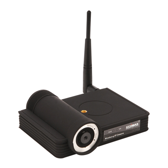
Hardware Installation 4.1. LED and Focusing The Camera head and its focus ring allow you to modify the aim and focus of the Camera. To adjust the Camera’s focus, rotate the dark focus ring. There are four LEDs indicating the camera status and netw orking status. Monitoring When someone is view ing the camera, the LED w ill light. -
Page 6: Camera Ports
4.2. Camera Ports The Camera features three ports and a Reset button. Antenna Connector This round connection is standard Reverse SMA connector where any antennas w ith Reverse SMA connector can connect to the Internet Camera. Power The Pow er port is where you can connect the pow er adapter. The LAN port is w here you can connect the Ethernet netw ork cable. -
Page 7: Installation Procedure
4.3. Installation Procedure 1. Unpack the Internet Camera package and verify that all the items listed in the Chapter 2 are provided. 2. Connect the Internet Camera to your netw ork by attached the netw ork cable from the sw itch/router to the UTP port of the Internet Camera. 3. -
Page 8: Software Installation
Software Installation Follow the simple steps below to run the Install Wizard to guide you quickly through the Installation process. The follow ing installation is implemented in Window s XP. The installation procedures in Windows 98SE/Me/2000/Server 2003 are similar. 1. Insert the CD shipped along w ith the Internet Camera into your CD- ROM drive. The “Autorun.exe”... - Page 9 3. The system w ill start the installation procedures. Click “ Next” to continue installation. 4. If you w ish to install the softw are program in an alternate location, click “Change”; otherw ise click “Next” to move on to the next step.
- Page 10 5. Click “ Install” to start installing the program. 6. The system w ill install the program automatically.
- Page 11 7. Click “Finish” to complete the softw are installation. 8. When the installation is completed. The system w ill auto run ”Administrator Utility“. On the Internet Camera first page, the cameras found in the netw ork are listed in the left w indow . Choose the one you w ant to configure and click “Setting Wizard”...
- Page 12 9. Please enter the default passw ord “1234” and click “OK” to login to the IP setup page. 10. Internet Camera is w orking through the netw ork (TCP/IP Protocol). The IP address setting must be correct, or you cannot access to the camera. The w izard program w ill detect the IP address status of your network automatically and suggest a free IP address for the Camera.
-
Page 13: Using The Administrator Utility
12. The “ Camera View er” w ill show the video automatically. Congratulations, you can use the camera through the netw ork to view the video from now on. Using the Administrator Utility The Administrator Utility allow s users to search and setup the cameras located w ithin the Intranet or on the Internet. -
Page 14: General Setting
IPCamera_MJPEG 6.1. General Setting Auto Discover Click the button w ill search the camera w ithin the netw ork automatically. Camera List The list show s the camera name and the setup status of the camera. It means the camera is in the default setting. It means the camera is configured before. -
Page 15: Detail Setting
Camera List The list show s the camera name and the connect status of the camera. It means the camera is disconnected or not in the Internet. It means the camera is connected. Inform ation of Camera Camera Information It displays all information of the selected camera. The information includes Firmw are Version, Netw ork Information, IP Address, UPnP Setting, DDNS Setting, Wireless Setting, Resolution and E- mail setting, etc. - Page 16 IPCamera_MJPEG If the name and passw ord you enter are correct, you can start to setup the camera.
-
Page 17: Network Setting
6.2.1. Network Setting Netw ork Setting Internet Camera Name The default camera name is “WIPCamera_MJPEG”. It is recommended to name a meaningful name for the camera. IP Address Enter an unused IP Address w ithin the IP address range used on your LAN. -
Page 18: Wireless Setting
Netw ork Setting Video Port The Video Port is used to transmit or receive the video streaming in the netw ork. The default port setting is “4321”. If you w ant to view the video from the camera, the port setting should be correct. - Page 19 Wireless Setting Wireless Setting Enable or disable the w ireless function of the Internet Camera. By default, the function is disabled. Available Network Available Netw ork This list show s all available w ireless networks within range of your Internet Camera. It also displays the information of the netw orks including the SSID and Signal Strength.
- Page 20 Profile List The “ Profiles List” is for you to manage the netw orks you connect to frequently. The profile list displays all the profiles and the relative settings of the profiles including Profile Name, SSID, Channel, etc. If you w ant to connect to any profiles on the list, double-click the profile or select the profile and click “Activate”, and the Internet Camera w ill automatically connect to the selected profile.
- Page 21 Encryption Enable or disable the encryption function for the wireless data communications. Key Length You may select 64-bit or 128-bit to encrypt transmitted data. Larger key length w ill provide higher level of security, but the throughput w ill be low er. Key For mat Hexdecimal –...
-
Page 22: E-Mail Setting
6.2.3. E-Mail Setting E-Mail Setting E- Mail Account This camera supports “Snap Shot” function. You can snapshot a picture and send the picture by E- Mail. Enter the E- Mail Account for receiving the picture. SMTP Server Enter the SMTP Server for the E-Mail sending. -
Page 23: Resolution
6.2.4. Resolution Resolution Resolution Select the desired video resolution format. Larger resolution requires more bandw idth. 640 x 480 is “VGA” format. 320 x 240 is “CIF” format. -
Page 24: Advanced Setting
6.2.5. Advanced Setting Advanced Setting UPnP When the UPnP function is enabled, the camera can be detected by UPnP compliant system such as Windows XP. The camera will be displayed in the Neighborhood of Window s XP, so you can directly click the camera to view the video through w eb browser. -
Page 25: Password
Advanced Setting Domain Name The domain name given by DynDNS is “registername.dyndns.com”. Enter the domain name that you register for the camera from DynDNS w eb site. Account Enter the login name for the DDNS service. Passw ord Enter the passw ord for the DDNS service. 6.2.6. -
Page 26: Tools
6.2.7. Tools Tools Fir mw are Version Display current firmw are version. Fir mw are Update The utility is not allow ed users to upgrade firmw are. Please upgrade firmw are in the Web Management. Reset to Default If you w ant to reset the camera, click this button. The default settings of the camera are as follow s. -
Page 27: About
6.2.8. About About Administrator Utility Display current Administrator Utility Version. Version... -
Page 28: Setting Wizard
6.3. Setting Wizard When you click the “Setting Wizard”, a screen w ill pop up for you to enter the “Administrator Name” and “ Passw ord”. The default value is as follow s. Name: “Adm in” Passw ord: “1234” If the name and passw ord you enter are correct, you can start to setup the camera. Setting Wizard Internet Camera Name The default camera name is “WIPCamera_MJPEG”. - Page 29 Setting Wizard IP Address The w izard will auto setup an available IP Address to the camera. For example: if the IP address of the netw ork is 192.168.2.x, the wizard will search an unused IP Address from 192.168.2.250 to 192.168.2.0 and assign the camera an available IP Address.
-
Page 30: Using The Camera Viewer
Using the Camera Viewer The Camera View er Utility allows users to view video from up to four cameras. It also allow s users to manual/schedule record video and playback the recording file. The status of camera view ing such as frame rate, video received, and etc. are also recorded in time. There are three w ays to run the Camera View er Utility as follows. -
Page 31: Camera Buttons
7.2. Camera Buttons... -
Page 32: Camera Status
Camera Buttons Camera Click one of these four cameras w ill connect to the selected camera that you w ant to view and configure. If you want to remove the camera from the view er, please right click the icon and select “Reset Camera x”. - Page 33 Control Buttons Play The “ Play” button is an intelligent play user-interface. In the normal display mode and the Internet Camera is disconnected, clicking on the “ Play” can make the view er connect to the Internet Camera. In the playback mode, clicking on the “ Play” can play the video in the normal speed.
-
Page 34: Video Recording
7.5. Video Recording This utility allow s you record the video in AVI format files. There are tw o ways of video recording – Manual Recording and Schedule Recording. Manual Recording You can manually record the video stream into an assigned video file. Click “Record”, then the “Record to Disk”... -
Page 35: Change Resolution
7.6. Change Resolution The Internet Camera supports tw o resolution, 640x480 (VGA) and 320x240 (CIF). You can change the resolution of each Internet Camera by clicking the resolution button. Note: Before changing the resolution of the Internet Camera, you have to select the Internet Camera by clicking the camera button first. -
Page 36: View Four Cameras Simultaneously
7.7. View Four Cameras Simultaneously Click the four division button can view the 4 cameras simultaneously in a four-division window. When 7.8. Viewer Utility Setting Click the “Setting” , then the setting w indow of the Internet Camera w ill pop up. Note: When you w ant to change the settings such as IP Address, Video Port, etc. -
Page 37: Setting
7.8.1. Setting... - Page 38 IPCamera_MJPEG Setting Name It is not required to fill the camera name for connecting camera. It is for users to identify the camera. IP Address IP address/Domain name of the Internet Camera. Video Port The number of service port used by the Internet Camera. Model Select “MJPEG Camera”...
-
Page 39: Recording
7.8.2. Recording You can setup schedule for the recording here. This utility w ill record the video stream in the assigned file folder according to the schedule automatically. The recorded video files are AVI format. Note: 1. The utility w ill only start to record the video stream w hen this utility is running and is successfully connecting to the Internet camera in the beginning of the schedule. - Page 40 One-Time Schedule Weekly Schedule Schedule Cycle Recording Select this item to enable cycle recording. When the Cycle Recording is enabled and the storage usage has already reached the maximum reserved storage space, the utility w ill automatically delete the oldest recorded video file and use the space to store the new l y recorded video stream.
-
Page 41: Status
Schedule Click “New” to add a new recording schedule. Edit Select an existing schedule in the schedule list and click “ Edit” to edit the schedule. Delete Select an existing schedule in the schedule list and click “Delete” to delete the schedule. 7.8.3. -
Page 42: General
Status Stream Started At The beginning time of the current connection session betw een the utility and the Internet Camera. Time Elapsed The elapsed time of the current connection session betw een the utility and the Internet Camera. Video Received The total size (Unit is KByte) of video stream received during the current connection session betw een the utility and the Internet Camera. -
Page 43: About
General Snap Shot Directory This lets you assign the directory where bitmap files w ill be stored when you click “Snapshot” to take pictures. The default folder is where the software program is installed, for example: “C:\Program Files\Internet Camera”. Record Directory This lets you assign the directory where the recorded video files will be stored. -
Page 44: Playback
About Camera View er Utility Display current Camera View er Utility Version. Version 7.9. Playback Click the “Open File” and a “Load File” w indow w ill be popped up. Select the file that you w ant to play. The view er will start to play the selected video file. - Page 45 Playing Control Play When the video playback is in Stop state, just click “ Play” and the view er will play the video file from the beginning point. When the video playback is in Pause state, just click “ Play” and the view er will play the video file from the current pause point.
-
Page 46: Rotate Video
Playing Control Forw ard If you w ant the view er to play the video file in a faster speed when the view er is playing the video file, just click “Forw ard” and the view er will double the playing speed. If you w ant the viewer play with the normal speed w hen the view er is playing w ith fast speed, just click “... -
Page 47: Web Connection And Setup
Web Connection and Setup You can use the Web browser to connect the camera for view ing or setting. Open the w eb browser and enter the IP Address of the camera to establish a connection. The default IP Address of the camera is “192.168.2.3”. When the w elcome screen appears, enter the “Admin Name”... -
Page 48: Camera Setting
8.1. Camera Setting Camera Setting Digital Zoom It allow s you to zoom in or zoom out the video size. Click “x2”, the image size in the display area w ill be magnified 2 times to the original size. In 640x480 resolution, only central area of the screen w ill be magnified tw o times. -
Page 49: Network Setting
Camera Setting Snapshot & Mail If you w ant to snapshot a picture for the current video, click this button. The system w ill send the picture to the E-Mail account you set up in the “ E- Mail Setting” immediately. Apply Click “Apply”... - Page 50 E- Mail Address Set up the E- Mail account as the receiver for the snapshot picture. SMTP Server Specify the SMTP mail server for sending E- Mail. Apply When you finish the “ E-Mail Setting”, click “Apply”. IP Inform ation IP Address Enter an unused IP Address w ithin the IP address range used on your LAN.
- Page 51 The default camera name is “WIPCamera_MJPEG”. It is Camera Name recommended to name a meaningful name for the camera. Firmware Display the current firmw are version of the camera. When you finish the “Camera Information”, click “Apply”. Apply DDNS Service Enable/Disable Enable or disable DDNS function of the camera.
- Page 52 To reset the camera to factory default, click “Apply”. Then, follow Reset to Default the instruction of the screen to complete the process. The factory defaults are as follow s. Camera Name: “WIPCamera_MJPEG” IP Address: “192.168.2.3” Subnet Mask: 255.255.255.0 Administrator Name: “Admin”, Passw ord: “1234” Video Port: “4321”, Web Port: “80”...
-
Page 53: Wireless Setting
8.3. Wireless Setting Wireless Setting Wireless Connection Enable or disable the w ireless function of the Internet Camera. By default, the function is disabled. Mode Infrastructure – This operation mode requires the presence of a Wireless LAN Access Point or Router. All communication is done via the Access Point or Router. - Page 54 Wireless Setting SSID The SSID (up to 32 printable ASCII characters) is the unique name identified in a WLAN. The ID prevents the unintentional merging of tw o co-located WLANs. You may specify a SSID for the card and then only the device with the same SSID can interconnect to the card.
- Page 55 Encryption Setting Key1 ~ Key4 The WEP keys are used to encrypt data transmitted in the wireless network. Fill the text box by follow ing rules below . 64-bit – Input 10-digit Hex values (in the “A-F”, “a-f” and “0-9” range) or 5-digit ASCII characters (including “a-z”...
-
Page 56: Password Setting
Site Survey Site Survey List The list displays the information of all the w ireless netw orks nearby the Internet Camera. The information includes Connect Status, SSID, BSSID, Signal, Channel, Encryption Setting and Netw ork Type. Refresh Button Click “Refresh” button to collect the new information of all the wireless networks nearby. - Page 57 User 1 / 2 / 3 / 4 Up to four sets of user name and passw ord can be added. Enter User Name the user name to be the login name to the camera. Password Enter up to 4 digits passw ord for the new user account. Enter the passw ord again to confirm the setting.
-
Page 58: Frequently Asked Questions
Frequently Asked Questions Q1: What is an Internet Camera? A: The Internet Camera is a standalone system connecting directly to an Ethernet or Fast Ethernet network. It is different from the conventional PC Camera; the Internet Camera is an all-in-one system with built-in CPU and web-based solutions providing a low cost solution that can transmit high quality video images for monitoring. -
Page 59: Technical Specifications
Technical Specifications Video specification Max Resolution: 640 x 480 pixels Sensor: 300,000K pixels 1/4" color CMOS sensor Gain control: Automatic Exposure: Automatic White Balance: Automatic Focal Length: 6.0 mm Aperture: F=1.8 Im age (Video Setting) Image compression: Motion-JPEG Image Video Digital 24-bit Color Frame rate: 30fps@CIF, 20fps@VGA Video resolution: 320x240, 640x480... -
Page 60: Appendix A Router/Gateway Setup For Internet Viewing
Appendix A Router/Gateway Setup for Internet Viewing To view Internet Camera across the Internet, you have to make sure Router/Gatew ay has configured to pass incoming TCP/UDP connections from remote PC to the Internet Camera. The Router/Gatew ay should set port forwarding or virtual server for the connections. Please illustration as below. - Page 61 Setup 1/Setup 2 If you w ant to view the video via Web Browser, you have to ensure the Router/Gatew ay has configured setup1 and setup 2. If the w eb port is not default port “80”, but changed to 8080. The remote user has to enter http://203.30.212.82:8080.
-
Page 62: Appendix B Viewing Via Upnp In Windows Xp
Appendix B Viewing via UPnP in Windows XP When the UPnP function is enabled, the camera can be detected by UPnP compliant system such as Window s XP. The camera w ill be displayed in the Neighborhood of Windows XP, so you can directly double click the camera or right click the camera and select “Invoke”... - Page 63 Enable UPnP in Windows XP SP2 If you can’t find the camera in the Neighborhood of Windows XP SP2 or you have seen the follow ing message w hen you double click the camera. You have to check if UPnP function is blocked by the firew all.
- Page 64 4. The “Windows Firew all” screen w ill be popped up, select “ Exceptions” option menu.
- Page 65 5. Enable “ UPnP Framew ork” from the “ Programs and Services list” and click “Ok”.
Need help?
Do you have a question about the 802.11g and is the answer not in the manual?
Questions and answers