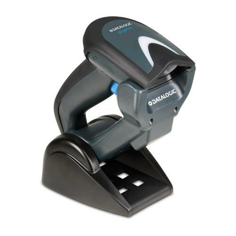
Datalogic Gryphon I GBT4400 Quick Reference Manual
General purpose handheld area imager bar code reader with bluetooth wireless technology
Hide thumbs
Also See for Gryphon I GBT4400:
- Product reference manual (332 pages) ,
- Quick reference manual (68 pages) ,
- Product reference manual (350 pages)

Related Manuals for Datalogic Gryphon I GBT4400


Summary of Contents for Datalogic Gryphon I GBT4400
- Page 1 Gryphon™ I GBT4400 General Purpose Handheld Area Imager Bar Code Reader with Bluetooth® Wireless Technology Quick Reference Guide...
- Page 2 Datalogic and the Datalogic logo are registered trademarks of Datalogic S.p.A. in many countries, including the U.S.A. and the E.U. All other brand and product names may be trademarks of their respective owners.
-
Page 3: Table Of Contents
Replacing the Batteries ..............16 Using the Gryphon™ I GBT4400 ............18 Linking the Reader ..................19 Link Datalogic RF Devices to Base ......... 19 Link Scanner to Bluetooth Adapter....... 19 Power Off ...................... 20 Selecting the Interface Type ..............20 Interface Selection ................. - Page 4 FCC RF Radiation Exposure Statement ......48 Canadian Notice ................48 Power Supply ................... 48 Imager Labeling ................49 Aiming System..............49 WEEE Statement ................54 Warranty ....................... 55 Ergonomic Recommendations ............. 56 Services and Support ................57...
-
Page 5: End User License Agreement
Agreement. If you do not intend to be bound to the terms of this Agreement, Datalogic is not willing to license the Software to you, you may not use the Datalogic Product or the Software, and you must contact the party from whom you acquired the Datalogic Product for instructions. -
Page 6: Limited Warranty
End User shall not sell, assign, sublicense, distribute, lend, rent, give, or other- wise transfer the Datalogic Product to any third party unless such third party agrees with Datalogic in writing to be bound by the terms and conditions of this Agreement. Any such transfer of the Datalogic Product absent such agree- ment shall be null and void. -
Page 7: Limitation Of Liability
Datalogic Scanning, Inc., Legal Department, 959 Terry Street, Eugene, OR 97402. In the defense or settlement of any such claim, Datalogic may, at its option, 1) procure for End User the right to continue using the Datalogic Product, 2) -
Page 8: Software Product Policy
The state or federal courts of the State of Oregon located in either Multnomah or Lane counties shall have exclusive jurisdiction over all matters regarding this Agreement, except that Datalogic shall have the right, at its absolute dis- cretion, to initiate proceedings in the courts of any other state, country, or ter- ritory in which End User resides, or in which any of End User's assets are located. -
Page 9: Description
Gryphon™ I GBT4400 Description With rich feature sets and extensive options, the Gryphon™ product series from Datalogic Scanning represents the premi- um level of data collection equipment for general purpose ap- plications. The Gryphon GBT4400 readers have enhanced optics with improved motion tolerance allowing codes placed... -
Page 10: Setting Up The Reader
Setting Up the Reader Setting Up the Reader Follow the steps below to connect and get your reader up and communicating with its host. Configure the Base Station starting on this page. Charge the Batteries (see page 14). Link to the Base Station (see page 19). Select the Interface Type (see page 20). - Page 11 Setting Up the Reader Insert the appropriate parts for the desired base station position, as shown below. Standing, Horizontal Horizontal Only or Vertical Using your thumbs, push open the plastic tabs on the bottom of the base to free the wing holders. Quick Reference Guide...
-
Page 12: Connecting The Base Station
Connecting the Base Station The stand can now be repositioned in either horizon- tal or standing position. Horizontal Standing Connecting the Base Station Figure 1 on page 9 shows how to connect the Base Station to a terminal, PC or other host device. Turn off the host before connection and consult the manual for that equipment (if necessary) before proceeding. -
Page 13: Securing The Dc Power Cord (Optional)
Connecting the Base Station Figure 1. Connecting the Base Station Wall plug Connector I/F Cable AC/DC Adapter DC Power Cord Base Station Securing the DC Power Cord (Optional) The DC power cord for the adapter can be secured to the bot- tom of the base in order to maximize the mechanical retention of the cable itself. - Page 14 Host Connection: ble type is compatible with your host equipment. The Gryphon I GBT4400 can be set up to require a PIN code when connecting to the host. If you are adding new equip- ment to a system that uses a custom security PIN, please see the PRG for information before proceeding.
-
Page 15: System And Network Layout
Connecting the Base Station Plug the AC Adapter into an approved AC Power Connection: wall socket with the cable facing downwards (as shown in Fig- ure 1) to prevent undue strain on the socket. To detach the cable, insert a paper clip Disconnecting the Cable: or similar object into the hole on the base, as shown. -
Page 16: Using The Bc40Xx™ Radio Base
The button can be used to force device connection via the Datalogic Aladdin Software tool, to force a BT disconnect, and for paging the scanner when it is activated. Refer to the Gryphon I GBT4400 Product Reference Guide (PRG) for a more detailed explanation. Gryphon™ I GBT4400... -
Page 17: Cleaning
Cleaning Cleaning Exterior surfaces and scan windows exposed to spills, smudges or debris accumulation require periodic cleaning to ensure best performance during scanning operations. Contacts on the scanner and the base should also be cleaned as needed to en- sure a good connection. Always use a soft, lint-free cloth or lens tissue dampened with isopropyl alcohol (or equivalent) or water-based window cleaner. -
Page 18: Charging The Batteries
) will indicate the sta- Table 1 tus of the battery. Before using the Battery, read “Battery Safety” in the follow- ing section. Datalogic recommends annual replacement of rechargeable battery packs to ensure maximum perfor- mance. Battery Safety To install, charge and/or perform any other action on the bat- tery, follow the instructions in this manual. - Page 19 Always charge the battery at 32° – 104°F (0° - 40°C) tem- perature range. Use only the authorized power supplies, battery pack, chargers, and docks supplied by your Datalogic reseller. CAUTION The use of any other power supplies can damage the device and void your warranty.
-
Page 20: Replacing The Batteries
Replacing the Batteries Before proceeding, read “Battery Safety” on the preced- ing pages. Datalogic recommends annual replacement of rechargeable battery packs to ensure maximum perfor- mance. Use the following procedure to change the reader’s battery: With a screwdriver, unscrew the battery cover screw. - Page 21 Charging the Batteries Carefully lift out the gold contacts circuit, and remove the battery holder cap while letting the white connec- tor pass through the hole in the battery holder (as shown below). Pass-through hole Gold contacts circuit Remove the old battery from its place (if present), and insert the new battery in the same position.
-
Page 22: Using The Gryphon™ I Gbt4400
Successful reading is signaled by an audible tone plus a good-read green spot LED indicator. Reference the Gryphon I GBT4400 Product Reference Guide (PRG) or Datalogic Aladdin configuration software (both available on the Datalogic website) for more information about this feature and other programmable settings. -
Page 23: Linking The Reader
Enable RF Link to Server The Gryphon I GBT4400 can be set up to require a PIN code when connecting. If you want to set up a PIN, or when add- ing new equipment to a system that uses a custom security PIN, please see the PRG for information. -
Page 24: Power Off
Power Off Power Off Scan the bar code below to shut off power to the BT handheld until the next trigger pull. PowerOff Selecting the Interface Type Upon completing the physical connection between the reader and its host, proceed directly to Interface Selection on page 20 for information and programming for the interface type the reader is connected to (for example: RS-232, Keyboard... - Page 25 Selecting the Interface Type RS-232 RS-232 standard interface Select RS232-STD RS-232 Wincor-Nixdorf Select RS232-WN RS-232 for use with OPOS/UPOS/JavaPOS Select RS-232 OPOS USB COM to simulate RS-232 standard interface Select USB-COM-STD a. Download the correct USB COM driver from www.datalogic.com Quick Reference Guide...
- Page 26 Selecting the Interface Type IBM-46xx Port 5B reader interface Select IBM-P5B IBM-46xx Port 9B reader interface Select IBM-P9B USB-OEM USB-OEM (can be used for OPOS/UPOS/JavaPOS) Select USB-OEM Gryphon™ I GBT4400...
-
Page 27: Keyboard Interface
Selecting the Interface Type Keyboard Interface Use the programming bar codes to select options for USB Keyboard and Wedge Interfaces. KEYBOARD AT, PS/2 25-286, 30-286, 50, 50Z, 60, 70, 80, 90 & 95 w/ Standard Key Encoding Select KBD-AT Keyboard Wedge for IBM AT PS2 with standard key encoding but without external keyboard Select KBD-AT-NK AT, PS/2 25-286, 30-286, 50, 50Z, 60, 70, 80, 90 &... - Page 28 Selecting the Interface Type KEYBOARD (continued) PC/XT w/Standard Key Encoding Select KBD-XT Keyboard Wedge for IBM Terminal 3153 Select KBD-IBM-3153 Keyboard Wedge for IBM Terminals 31xx, 32xx, 34xx, 37xx make only keyboard Select KBD-IBM-M Keyboard Wedge for IBM Terminals 31xx, 32xx, 34xx, 37xx make break keyboard Select KBD-IBM-MB USB Keyboard with alternate key encoding...
-
Page 29: Scancode Tables
Selecting the Interface Type KEYBOARD (continued) Keyboard Wedge for DIGITAL Terminals VT2xx, VT3xx, VT4xx Select KBD-DIG-VT USB Keyboard with standard key encoding Select USB Keyboard WAND EMULATION Wand Emulation Select WAND Scancode Tables Reference the Gryphon™ PRG for information about control character emulation which applies to keyboard interfaces. - Page 30 Selecting the Interface Type COUNTRY MODE ENTER/EXIT PROGRAMMING MODE Country Mode = U.S. Country Mode = Belgium Country Mode = Britain Country Mode = Croatia* *Supports only the interfaces listed in the Country Mode feature description Gryphon™ I GBT4400...
- Page 31 Selecting the Interface Type COUNTRY MODE (Continued) Country Mode = Czech* Country Mode = Denmark* Country Mode = France Country Mode = Germany Country Mode = Hungary* Country Mode = Italy *Supports only the interfaces listed in the Country Mode feature description Quick Reference Guide...
- Page 32 Selecting the Interface Type COUNTRY MODE (Continued) Country Mode = Japanese 106-key* Country Mode = Norway* Country Mode = Poland* Country Mode = Portugal* Country Mode = Romania* Country Mode = Spain *Supports only the interfaces listed in the Country Mode feature description Gryphon™...
- Page 33 Selecting the Interface Type COUNTRY MODE (Continued) Country Mode = Sweden Country Mode = Slovakia* Country Mode = Switzerland* *Supports only the interfaces listed in the Country Mode feature description Quick Reference Guide...
-
Page 34: Caps Lock State
Selecting the Interface Type Caps Lock State This option specifies the format in which the reader sends character data. This applies to keyboard wedge interfaces. This does not apply when an alternate key encoding keyboard is se- lected. ENTER/EXIT PROGRAMMING MODE Caps Lock State = Caps Lock OFF Caps Lock State = Caps Lock ON Caps Lock State = AUTO Caps Lock Enable... -
Page 35: Numlock
Selecting the Interface Type Numlock This option specifies the setting of the Numbers Lock (Num- lock) key while in keyboard wedge interface. This only applies to alternate key encoding interfaces. It does not apply to USB keyboard. ENTER/EXIT PROGRAMMING MODE Numlock = Numlock key unchanged Numlock = Numlock key toggled Quick Reference Guide... -
Page 36: Programming
Programming Programming The reader is factory-configured with a set of standard default features. After scanning the interface bar code from the Inter- faces section, select other options and customize your reader through use of the programming bar codes available in the Product Reference Guide (PRG). -
Page 37: Reading Parameters
Reading Parameters Reading Parameters Point the reader at the target and pull the trigger to enable the aiming system and the illuminator (red beam) to capture and decode the image. The aiming system will briefly switch off during the acquisition time and if no code is decoded will switch on again before the next acquisition. -
Page 38: Good Read Green Spot Duration
Reading Parameters Good Read Green Spot Duration Successful reading can be signaled by a good read green spot. Use the bar codes below to specify the duration of the good read pointer beam after a good read. ENTER/EXIT PROGRAMMING MODE Green Spot Duration = Disable (Green Spot is Off) Green Spot Duration = Short (300 msec) Green Spot Duration = Medium (500 msec) -
Page 39: Scan Modes
Scan Modes Scan Modes The imager can operate in one of several scanning modes. When the trigger is pulled, scanning is activat- Trigger Single — ed until one of the following occurs: - a programmable duration has elapsed - a label has been read - the trigger is released This mode is associated with typical handheld reader opera- tion. - Page 40 Scan Modes SCAN MODE ENTER/EXIT PROGRAMMING MODE Scan Mode = Trigger Single Scan Mode = Trigger Hold Multiple Scan Mode = Trigger Pulse Multiple Scan Mode = Flashing Scan Mode = Always On Scan Mode = Stand Mode Gryphon™ I GBT4400...
-
Page 41: Pick Mode
Scan Modes Pick Mode Pick Mode is a Decoding and Transmission process where bar codes that are not within the configurable distance from the center of the aiming pattern are not acknowledged or trans- mitted to the host. It is active only while the scanner is in Trig- ger Single mode. -
Page 42: Technical Specifications
Technical Specifications Technical Specifications The following table contains Physical and Performance Char- acteristics, User Environment and Regulatory information. Physical Characteristics White/Gray Color Black/Gray Height 7.1”/181 mm Dimensions Length 3.9”/100 mm Width 2.8”/71 mm Approximately Weight (without cable) 8.7 ounces/246 g (reader with display) 8.7 ounces/246 g (base charger) Electrical Characteristics Battery Type... - Page 43 Technical Specifications Depth of Field (Typical) Symbology 5mil: 1.6” -7.5” (4.0 -19cm) 3mil: 0.9” - 3.6” (2.4 - 9.1cm) Code 39 10mil: 0.4” - 11..8” (1.0 - 30cm) 5 mil: 0.3” - 4.5” (0.8 -11.3cm) 20mil: up to 17.7” (up to 45cm) 7.5mil: 0.5”...
- Page 44 PPT; Code 32 (Italian Pharmacode 39); Code 128; Code 128 ISBT; Interleaved 2 of 5; Standard 2 of 5; Interleaved 2 of 5 CIP (HR); Industrial 2 of 5; Discrete 2 of 5; Datalogic 2 of 5 (China Post Code/Chinese 2 of 5); IATA 2of5 Air cargo code; Code 11; Codabar; Codabar (NW7); ABC Coda- bar;...
- Page 45 Technical Specifications Scanner withstands 18 drops from 1.8 meters Drop Specifications (5.9 feet) to concrete Ambient Light Immunity Up to 100,000 Lux Contaminants Spray/rain IEC 529-IP52 (scanner only) Dust/particulates ESD Level 16 KV Regulatory Electrical Safety UL 60950, CSA C22.2 No. 60950, IEC 60950 Europe - CE;...
-
Page 46: Led And Beeper Indications
LED and Beeper Indications LED and Beeper Indications The reader’s beeper sounds and its LED illuminates to indicate various functions or errors on the reader. An optional “Green Spot” also performs useful functions. The following tables list these indications. One exception to the behaviors listed in the tables is that the reader’s functions are programmable, and so may or may not be turned on. - Page 47 LED and Beeper Indications Indication Description Beeper Upon successful read of a label, the soft- Green Spot ware shall turn the flashes green spot on for the momentarily time specified by the configured value. Blue light flashes Image When ready to cap- 2 times when Capture ture image...
-
Page 48: Programming Mode
LED and Beeper Indications Programming Mode - The following indications ONLY occur when the reader is in Programming Mode. INDICATION DESCRIPTION BEEPER A valid programming LED blinks Reader sounds Label Programming label has been continu- four low fre- Mode Entry scanned. -
Page 49: Error Codes
Error Codes Error Codes Upon startup, if the reader sounds a long tone, this means the reader has not passed its automatic Selftest and has entered FRU (Field Replaceable Unit) isolation mode. If the reader is reset, the sequence will be repeated. The following table de- scribes the LED flashes/beep codes associated with an error found. -
Page 50: Base Station Indications
Base Station Indications Base Station Indications Indication LEDS Power-up Complete Yellow LED on Reader Disabled by the HOST or the communication with HOST is Yellow LED blinking ~1Hz not established Data/labels are transmitted to the Yellow LEDs turned off HOST for 100mSec Programming Mode Yellow LED blinks quickly... -
Page 51: Statement Of Agency Compliance
Any changes or modifications to equipment, not expressly ap- proved by Datalogic could void the user's authority to operate the equipment. Statement of Agency Compliance This device complies with part 15 of the FCC Rules. -
Page 52: Fcc Rf Radiation Exposure Statement
Statement of Agency Compliance FCC RF Radiation Exposure Statement Exposure to Radio-Frequency Radiation CAUTION To comply with FCC RF exposure compliance requirements, for mobile configurations, a separation distance of at least 20 cm must be maintained between the antenna of this device and all persons. -
Page 53: Imager Labeling
Statement of Agency Compliance Imager Labeling Sample labels are shown for illustrative purposes only. Please view the labels on your product for actual details, as they may vary from those depicted. Scanner Regulatory Label Base Station Label Aiming System ™ The Gryphon aiming system meets the Class 2 require- ments for laser safety. - Page 54 Statement of Agency Compliance LA LUCE LE RAYON DIE LASER-STRAH- LASER È VISI- LASER EST VISI- LUNG IST FÜR DAS A LUZ LÁSER ES BILE BLE À L'OEIL MENSCHLICHE VISIBLE AL OJO ALL'OCCHIO NU ET IL EST AUGE SICHTBAR HUMANO Y ES UMANO E ÉMIS PAR LA UND WIRD AM...
- Page 55 Statement of Agency Compliance The product utilizes a low-power laser diode. Although staring directly at the laser beam momentarily causes no known bio- logical damage, avoid staring at the beam as one would with any very strong light source, such as the sun. Avoid allowing the laser beam to hit the eye of an observer, even through re- flective surfaces such as mirrors, etc.
- Page 56 Statement of Agency Compliance Es ist nicht notwendig, das Gerät wegen Betrieb oder Installa- tions-, und Wartungs-Arbeiten zu öffnen. Jegliche Änderungen am Gerät sowie Vorgehens- weisen, die nicht in dieser Betriebsanleitung besch- reiben werden, können ein gefährliches Laserlicht verursachen. ACHTUNG Der Produkt benutzt eine Laserdiode.
- Page 57 Statement of Agency Compliance ESPAÑOL Las informaciones siguientes son presentadas en conformidad con las disposiciones de las autoridades internacionales y se re- fieren al uso correcto del terminal. NORMATIVAS ESTÁNDAR PARA SEGURIDAD LÁSER Este aparato resulta conforme a las normativas vigentes de se- guridad láser a la fecha de producción: CDRH 21 CFR 1040 y EN 60825-1.
-
Page 58: Weee Statement
Waste Electrical and Electronic Equipment (WEEE) Statement English For information about the disposal of Waste Electrical and Electronic Equipment (WEEE), please refer to the website at www.scanning.datalogic.com. Italian Per informazioni sullo smaltimento delle apparecchiature elettriche ed elettroniche consultare il sito Web www.scanning.datalogic.com. -
Page 59: Warranty
Datalogic. Risk of Loss Customer shall bear risk of loss or damage for product in transit to Datalogic. Data- logic shall assume risk of loss or damage for product in Datalogic's possession or product being returned to Customer by Datalogic, except such loss or damage as may be caused by the negligence of Customer, its agents or employees. -
Page 60: Ergonomic Recommendations
Ergonomic Recommendations Ergonomic Recommendations In order to avoid or minimize the potential risk of ergo- nomic injury follow the recommendations below. Consult with your local Health & Safety Manager to ensure that you CAUTION are adhering to your company’s safety programs to prevent employee injury. -
Page 61: Services And Support
Services and Support Services and Support Datalogic provides several services as well as technical support through its website. Log on to www.scanning.datalogic.com and click on the links indicated for further information. Products Search through the links to arrive at your product page where... - Page 62 Services and Support NOTES Gryphon™ I GBT4400...
-
Page 63: Declaration Of Conformity
DECLARATION OF CONFORMITY EC-063 Rev.: 0 Pag.: 1 di 1 Datalogic Scanning, Inc. 959 Terry Street Eugene, Oregon 97402 dichiara che declares that the déclare que le bescheinigt, daß das Gerät declare que el Gryphon GBT 4400; Cordless Barcode Reader Gryphon BC 40X0-YY-BT;... - Page 64 Telephone: 49 (0) 61 51/93 58-0 Telephone: (65) 6435-1311 germany.scanning@datalogic.com singapore.scanning@datalogic.com India Iberia Datalogic Scanning India Datalogic Scanning SAS Sucursal en España Telephone: 91- 22 - 64504739 Telephone: 34 91 746 28 60 india.scanning@datalogic.com spain.scanning@datalogic.com Italy United Kingdom Datalogic Scanning SpA Datalogic Scanning LTD Telephone: [39] (0) 39/62903.1...