Datalogic Gryphon GBT4100 Quick Reference Manual
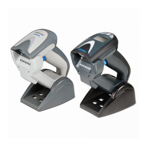
General purpose handheld linear imager barcode reader with bluetooth wireless technology
Hide thumbs
Also See for Gryphon GBT4100:
- Specifications (2 pages) ,
- Quick reference manual (60 pages) ,
- Quick reference manual (60 pages)

Related Manuals for Datalogic Gryphon GBT4100


Summary of Contents for Datalogic Gryphon GBT4100
- Page 1 Gryphon™ I GBT4100 General Purpose Handheld Linear Imager Barcode Reader with Bluetooth® Wireless Technology Quick Reference Guide...
- Page 2 Datalogic and the Datalogic logo are registered trademarks of Datalogic S.p.A. in many countries, including the U.S.A. and the E.U. All other brand and product names may be trademarks of their respective owners.
-
Page 3: Table Of Contents
Charging the Batteries ................11 Battery Safety ..................12 Replacing the Batteries ..............14 Linking the Reader ..................16 Link Datalogic RF Devices to Base ........16 Link Scanner to Bluetooth Adapater ......16 System and Network Layout ............17 Typical Setup with Cradle and Host........ 17 Selecting the Interface Type ..............18... - Page 4 NOTES...
-
Page 5: End User License Agreement
This End User Software License Agreement ("Agreement") is a legally binding agree- ment governing the licensing of the Software and Documentation by Datalogic Scan- ning, Inc. and its Affiliates ("Datalogic") to the entity or person who has purchased or otherwise acquired a Datalogic Product ("End User"). For purposes of this Agreement, any software that is associated with a separate end-user license agreement is licensed to you under the terms of that license agreement. - Page 6 End User shall not sell, assign, sublicense, distribute, lend, rent, give, or other- wise transfer the Datalogic Product to any third party unless such third party agrees with Datalogic in writing to be bound by the terms and conditions of this Agreement. Any such transfer of the Datalogic Product absent such agree- ment shall be null and void.
- Page 7 Datalogic Scanning, Inc., Legal Department, 959 Terry Street, Eugene, OR 97402. In the defense or settlement of any such claim, Datalogic may, at its option, 1) procure for End User the right to continue using the Datalogic Product, 2)
-
Page 8: Software Product Policy
State of Oregon located in either Multnomah or Lane counties shall have exclusive jurisdiction over all matters regarding this Agree- ment, except that Datalogic shall have the right, at its absolute discretion, to initiate proceedings in the courts of any other state, country, or territory in which End User resides, or in which any of End User's assets are located. -
Page 9: Configuring The Base Station
Setting Up the Reader Follow the steps below to connect and get your reader up and communicating with its host. Configure the Base Station starting on this page. Charge the Batteries (see page 11). Link to the Base Station (see page 16). Select the Interface Type (see page 18). - Page 10 Configuring the Base Station Insert the appropriate parts for the desired base station position, as shown below. Standing, Horizontal Horizontal Only or Vertical Using your thumbs, push open the plastic tabs on the bottom of the base to free the wing holders. Gryphon™...
-
Page 11: Connecting The Base Station
Connecting the Base Station The stand can now be repositioned in either horizontal or standing position. Horizontal Standing Connecting the Base Station Figure 1 shows how to connect the Base Station to a terminal, PC or other host device. Turn off the host before connection and con- sult the manual for that equipment (if necessary) before proceed- ing. -
Page 12: Securing The Dc Power Cord (Optional)
Connecting the Base Station Figure 1. Connecting the Base Station Wall plug Connector I/F Cable AC/DC Adapter DC Power Cord Base Station Securing the DC Power Cord (Optional) The DC power cord for the adapter can be secured to the bottom of the base in order to maximize the mechanical retention of the cable itself. - Page 13 Connecting the Base Station Figure 3. Arrows showing routing Verify before connection that the reader’s cable Host Connection: type is compatible with your host equipment. Most connections plug directly into the host device as shown in Figure 4 on page 9. Keyboard Wedge interface cables have a ‘Y’...
-
Page 14: Using The Bc40Xx™ Radio Base
Connecting the Base Station Gryphon BT can also be Powered by the Terminal. The exter- nal power supply is recommended but not necessary. When powered by the Terminal, the battery charger is automati- cally set as Slow charge. NOTE To detach the cable, insert a paper clip Disconnecting the Cable: or similar object into the hole on the base, as shown in Figure 5. -
Page 15: Charging The Batteries
The LEDs on the base (shown in above) will indicate the Table 1 status of the battery. Before using the Battery, read “Battery Safety” in the following section. Datalogic recommends annual replacement of rechargeable battery packs to ensure maximum performance. NOTE Quick Reference Guide... -
Page 16: Battery Safety
Always charge the battery at 32° – 104°F (0° - 40°C) tem- perature range. Use only the authorized power supplies, battery pack, chargers, and docks supplied by your Datalogic reseller. CAUTION The use of any other power supplies can damage the device and void your warranty. - Page 17 Charging the Batteries Do not place the battery in or near fire, on stoves or other high temperature locations. Do not place the battery in direct sunlight, or use or store the battery inside cars in hot weather. Doing so CAUTION may cause the battery to generate heat, explode or ignite.
-
Page 18: Replacing The Batteries
Charging the Batteries Replacing the Batteries Before proceeding, read “Battery Safety” on the preceding pages. Datalogic recommends annual replacement of rechargeable battery packs to ensure maximum performance. NOTE Use the following procedure to change the reader’s battery: With a screwdriver, unscrew the battery cover screw. - Page 19 Charging the Batteries Carefully lift out the gold contacts circuit, and remove the battery holder while letting the white connector pass through the hole in the battery holder (as shown below). Pass-through hole Gold contacts circuit Remove the old battery from its place (if present), and insert the new battery in the same position.
-
Page 20: Linking The Reader
Scan the Enable RF Link to Server label below to make the scanner visible to the host computer. Use the host computer’s Bluetooth manager to “Discover new devices” and select "Datalogic Scanner." If you receive an error message, it may be necessary to disable security on the device. -
Page 21: System And Network Layout
Linking the Reader System and Network Layout Typical Setup with Cradle and Host Figure 7. Reader Layout Quick Reference Guide... -
Page 22: Selecting The Interface Type
Selecting the Interface Type Selecting the Interface Type Upon completing the physical connection between the reader and its host, proceed directly to for in- Interface Selection on page 18 formation and programming for the interface type the reader is connected to (for example: RS-232, Keyboard Wedge, USB, etc.) and scan the appropriate barcode to select your system’s correct interface type. - Page 23 Selecting the Interface Type RS-232 RS-232 standard interface Select RS232-STD RS-232 Wincor-Nixdorf Select RS232-WN RS-232 for use with OPOS/UPOS/JavaPOS Select RS-232 OPOS USB Com to simulate RS-232 standard interface Select USB-COM-STD Quick Reference Guide...
- Page 24 Selecting the Interface Type IBM-46xx Port 5B reader interface Select IBM-P5B IBM-46xx Port 9B reader interface Select IBM-P9B USB-OEM USB-OEM (can be used for OPOS/UPOS/JavaPOS) Select USB-OEM a. Download the correct USB Com driver from www.datalogic.com Gryphon™ I GBT4100...
-
Page 25: Keyboard Interface
Selecting the Interface Type Keyboard Interface Use the programming barcodes to select options for USB Keyboard and Wedge Interfaces. KEYBOARD AT, PS/2 25-286, 30-286, 50, 50Z, 60, 70, 80, 90 & 95 w/ Standard Key Encoding Select KBD-AT Keyboard Wedge for IBM AT PS2 with standard key encoding but without external keyboard Select KBD-AT-NK AT, PS/2 25-286, 30-286, 50, 50Z, 60, 70, 80, 90 &... - Page 26 Selecting the Interface Type KEYBOARD (continued) PC/XT w/Standard Key Encoding Select KBD-XT Keyboard Wedge for IBM Terminal 3153 Select KBD-IBM-3153 Keyboard Wedge for IBM Terminals 31xx, 32xx, 34xx, 37xx make only keyboard Select KBD-IBM-M Keyboard Wedge for IBM Terminals 31xx, 32xx, 34xx, 37xx make break keyboard Select KBD-IBM-MB Keyboard Wedge for DIGITAL Terminals VT2xx, VT3xx, VT4xx...
-
Page 27: Scancode Tables
Selecting the Interface Type KEYBOARD (continued) USB Keyboard with alternate key encoding Select USB Alternate Keyboard USB Keyboard for Apple computers Select USB-KBD-APPLE WAND EMULATION Wand Emulation Select WAND Scancode Tables Reference the Gryphon™ I PRG for information about control character emulation which applies to keyboard interfaces. - Page 28 Selecting the Interface Type COUNTRY MODE ENTER/EXIT PROGRAMMING MODE Country Mode = U.S. Country Mode = Belgium Country Mode = Britain Country Mode = Croatia* *Supports only the interfaces listed in the Country Mode feature description Gryphon™ I GBT4100...
- Page 29 Selecting the Interface Type COUNTRY MODE (continued) Country Mode = Czechoslovakia* Country Mode = Denmark* Country Mode = France Country Mode = Germany Country Mode = Hungary* Country Mode = Italy *Supports only the interfaces listed in the Country Mode feature description Quick Reference Guide...
- Page 30 Selecting the Interface Type COUNTRY MODE (continued) Country Mode = Japanese 106-key* Country Mode = Norway* Country Mode = Poland* Country Mode = Portugal* Country Mode = Romania* Country Mode = Slovakia* *Supports only the interfaces listed in the Country Mode feature description Gryphon™...
- Page 31 Selecting the Interface Type COUNTRY MODE (continued) Country Mode = Spain Country Mode = Sweden Country Mode = Switzerland* *Supports only the interfaces listed in the Country Mode feature description Quick Reference Guide...
-
Page 32: Caps Lock State
Selecting the Interface Type Caps Lock State This option specifies the format in which the reader sends charac- ter data. This applies to keyboard wedge interfaces. This does not apply when an alternate key encoding keyboard is selected. ENTER/EXIT PROGRAMMING MODE Caps Lock State = Caps Lock OFF Caps Lock State = Caps Lock ON Caps Lock State = AUTO Caps Lock Enable... -
Page 33: Numlock
Selecting the Interface Type Numlock This option specifies the setting of the Numbers Lock (Numlock) key while in keyboard wedge interface. This only applies to alter- nate key encoding interfaces. It does not apply to USB keyboard. ENTER/EXIT PROGRAMMING MODE Numlock = Numlock key unchanged Numlock = Numlock key toggled Quick Reference Guide... -
Page 34: Programming
Programming Programming The reader is factory-configured with a set of standard default fea- tures. After scanning the interface barcode from the Interfaces sec- tion, you can select other options and customize your reader through use of the instructions and programming barcodes avail- able in the Gryphon™... -
Page 35: Stand Detection
Stand Detection Stand Detection The following labels control how the scanner behaves when it is placed into a cradle or stand that has the hardware to support au- tomatic stand detection. Automatically switches the scanner to Switch to Stand Mode: Stand Mode when the scanner is placed in the stand. -
Page 36: Technical Specifications
Technical Specifications Technical Specifications The following table contains Physical and Performance Charac- teristics, User Environment and Regulatory information. Item Description Physical Characteristics White/Gray Color Black/Gray Height 7.1”/181 mm Dimensions Length 3.9”/100 mm Width 2.8”/71 mm Approximately Weight (without cable) 8.7 ounces/246 g (reader with display) 8.7 ounces/246 g (base charger) Electrical Characteristics Battery Type... - Page 37 Technical Specifications Item Description Minimum Element Width 3 mil Print Contrast Minimum 15% minimum reflectance UPC/EAN/JAN, P2 /P5 add-ons; Code 39; Italian Phar- macode 39; Code 128; C128 ISBT; Code 128 add-ons; I 2 Decode Capability of 5; Standard 2 of 5; Code 11;Codabar; EAN 128; Code 93;...
- Page 38 Technical Specifications Item Description Regulatory Electrical Safety UL 60950, CSA C22.2 No. 60950, IEC 60950 Obtained: Europe - CE, Australia - C-tick, Russia – GOST, USA/CANADA – FCC/IC, Japan – JRF/VCCI EMI/RFI Pending: Mexico - NOM + Cofetel, South Korea - KCC, Brazil - ANATEL, Argentina - CNC LED class safety IEC Class 1...
-
Page 39: Led And Beeper Indications
LED and Beeper Indications LED and Beeper Indications The reader’s beeper sounds and its LED illuminates to indicate various functions or errors on the reader. An optional “Green Spot” also performs useful functions. The following tables list these indications. One exception to the behaviors listed in the ta- bles is that the reader’s functions are programmable, and may or may not be turned on. -
Page 40: Programming Mode
INDICATION DESCRIPTION BEEPER The reader has Reader The LED blinks been disabled by Disabled continuously the host. While in Stand Mode or Trigger Stand Mode the Green Spot is on green spot shall continuously be on while in stand watch state. -
Page 41: Error Codes
Error Codes INDICATION DESCRIPTION BEEPER Configuration option(s) have Reader sounds Label Program- been successfully one high fre- ming Mode programmed via quency beep and Acceptance of labels and the 4 low frequency Programming reader has exited beeps followed Programming by reset beeps. Mode. -
Page 42: Base Station Indications
Base Station Indications Base Station Indications INDICATION LEDS Power-up Complete Yellow LED on Reader Disabled by the HOST or the com- Yellow LED blinking ~1Hz munication with HOST is not established Yellow LEDs turned off for Data/labels are transmitted to the HOST 100mSec Programming Mode Yellow LED blinks quickly... -
Page 43: Statement Of Agency Compliance
All models are designed to be compliant with rules and regula- tions in locations they are sold and will be labeled as required. Any changes or modifications to equipment, not expressly ap- proved by Datalogic could void the user's authority to operate the equipment. Statement of Agency Compliance This device complies with part 15 of the FCC Rules. -
Page 44: Fcc Rf Radiation Exposure Statement
Statement of Agency Compliance FCC RF Radiation Exposure Statement Exposure to Radio-Frequency Radiation CAUTION To comply with FCC RF exposure compliance requirements, for mobile configurations, a separation distance of at least 20 cm must be maintained between the antenna of this device and all persons. -
Page 45: Imager Labeling
Cleaning Imager Labeling Sample labels are shown here to illustrate their location only. Please view the labels on your product for actual details. Scanner Regulatory Label Base Station Label Cleaning Exterior surfaces and scan windows exposed to spills, smudges or debris accumulation require periodic cleaning to ensure best per- formance during scanning operations. -
Page 46: Weee Statement
Waste Electrical and Electronic Equipment (WEEE) Statement English For information about the disposal of Waste Electrical and Electronic Equipment (WEEE), please refer to the website at www.scanning.datalogic.com. Italian Per informazioni sullo smaltimento delle apparecchiature elettriche ed elettroniche consultare il sito Web www.scanning.datalogic.com. -
Page 47: Warranty
The warranty period shall ex- tend from the date of shipment from Datalogic for the duration published by Datalogic for the product at the time of purchase (Warranty period). Datalogic warrants repaired... -
Page 48: Ergonomic Recommendations
POSSIBILITY OF SUCH DAMAGES. Risk of Loss Customer shall bear risk of loss or damage for product in transit to Datalogic. Data- logic shall assume risk of loss or damage for product in Datalogic’s possession. In the absence of specific written instructions for the return of product to Customer, Data- logic will select the carrier, but Datalogic shall not thereby assume any liability in con- nection with the return shipment. -
Page 49: Services And Support
Services and Support Services and Support Datalogic provides several services as well as technical support through its website. Log on to www.scanning.datalogic.com and click on the links indicated for further information. Products Search through the links to arrive at your product page where you can download specific Manuals and Software &... - Page 50 Services and Support NOTES Gryphon™ I GBT4100...
-
Page 51: Declaration Of Conformity
EC-062 DECLARATION OF CONFORMITY Rev.:1 Pag.:1 di 1 Datalogic Scanning Group Srl Via S. Vitalino, 13 Lippo di Calderara di Reno (BO) 40012 Italy dichiara che declares that the déclare que le bescheinigt, daß das Gerät declara que el Gryphon GBT41xx-YY ; Cordless Barcode Reader Gryphon BC 40X0-YY-BT ;... - Page 52 Telephone: 49 (0) 61 51/93 58-0 Telephone: (65) 6435-1311 germany.scanning@datalogic.com singapore.scanning@datalogic.com India Iberia Datalogic Scanning India Datalogic Scanning SAS Sucursal en España Telephone: 91- 22 - 64504739 Telephone: 34 91 746 28 60 india.scanning@datalogic.com spain.scanning@datalogic.com Italy United Kingdom Datalogic Scanning SpA Datalogic Scanning LTD Telephone: [39] (0) 39/62903.1...
Need help?
Do you have a question about the Gryphon GBT4100 and is the answer not in the manual?
Questions and answers