Table of Contents
Advertisement
SPLIT-TYPE, AIR CONDITIONERS
TECHNICAL & SERVICE MANUAL
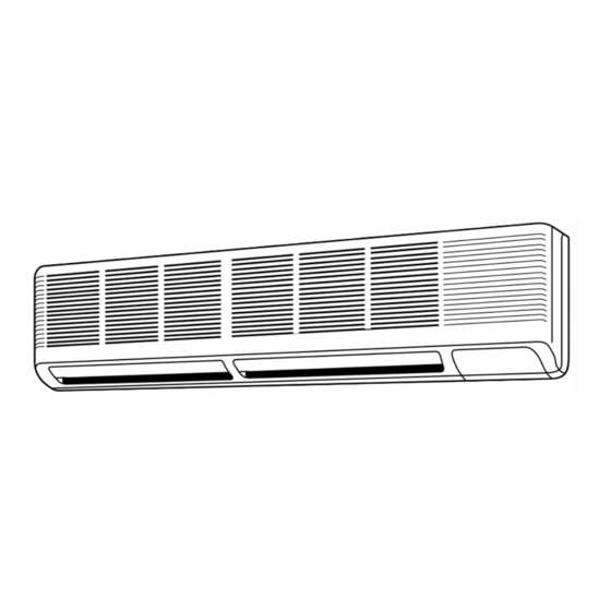
Wall Mounted
Series PK
<Indoor unit>
PK12FK / PU12EK
Models
PK18FK / PU18EK
PK24FK / PU24EK
PK30FK / PU30EK
PK36FK / PU36EK
Indoor unit
<Outdoor unit>
1
1
1
1
•CENTRALLY CONTROLLED•
POWER
ON/OFF
ON
DRY
MODE SELECT
FAN
COOL/DRY
FAN
COOL
CHECK
SET
WARMER
COOLER
SET TEMP
F
TEMPERATURE
TIMER OFF
TIMER
MODE
HOURS
AUTO STOP
HR
AUTO START
LOW HIGH
FAN SPEED LOW/HIOGH
AIR
SWING
UP/DOWN
STOP
DISCHARGE
F
AUTO RETURN
CHECK TEST RUN
CHECK
TEST RUN
MITSUBISHI ELECTRIC
REMOTE CONTROLLER
CONTENTS
1. FEATURES ···········································2
2. SPECIFICATIONS·································5
3. DATA ·····················································6
4. OUTLINES AND DIMENSIONS··········13
5. REFRIGERANT SYSTEM DIAGRAM ······21
6. WIRING DIAGRAM·····························22
7. OPERATION FLOW-CHART ··············26
8. MICROPROCESSOR CONTROL·······29
9. TROUBLESHOOTING ························40
10. SYSTEM CONTROL ···························48
11. DISASSEMBLY INSTRUCTIONS ·······53
12. PARTS LIST········································60
13. OPTIONAL PARTS ·····························74
The Slim Line.
From Mitsubishi Electric.
R
No. OC121
Advertisement
Table of Contents

Related Manuals for Mitsubishi Electric PK12FK


Summary of Contents for Mitsubishi Electric PK12FK
-
Page 1: Wall Mounted
SPLIT-TYPE, AIR CONDITIONERS No. OC121 TECHNICAL & SERVICE MANUAL Wall Mounted Series PK <Indoor unit> <Outdoor unit> PK12FK / PU12EK Models PK18FK / PU18EK PK24FK / PU24EK PK30FK / PU30EK PK36FK / PU36EK CONTENTS 1. FEATURES ···········································2 2. SPECIFICATIONS·································5 3. DATA ·····················································6 4. -
Page 2: Compact Design
The PK series models have been downsized and now require such minimal wall space that they can even be installed above windows. For the PK12FK, 11-13/16in, of wall space between the ceiling and the window allows “above window” installation (13-3/8in for the PK24/30/36FK) 2. - Page 3 TEST RUN 3) Convenient 24-Hour ON-OFF Timer The timer allows Mr.SLIM to be switched on or off automatically at the MITSUBISHI ELECTRIC time you set. Once the timer is set, the remaining time is shown on the LCD. 4) Self-Diagnostic Feature Indicates Faults Instantly In the rare case when a problem occurs, the unit stops operating and the set temperature indicator changes to the self-diagnostic indicator, indicating the location of the fault.
-
Page 4: Indoor Unit
7. HIGH RELIABILITY AND EASY SERVICING In addition to the self-diagnostic function, units are also equipped with a 3-minute time delay mechanism (cooling), an auto restart function, an emergency operation function, a test run switch, etc., to assure high reliability and easy servicing. 8. -
Page 5: Specifications
SPECIFICATIONS Model PK12FK PK18FK PK24FK PK30FK PK36FK Item Capacity Btu/h 12,500 18,500 24,000 30,000 34,200 Power consumption 1.21 1.75 2.34 3.06 3.47 10.3 10.6 10.3 SEER 11.3 10.6 10.7 10.2 11.5 INDOOR UNIT MODEL PK12FK PK18FK PK24FK PK30FK PK36FK External finish Munsell 3.4Y7.7/0.8... -
Page 6: Cooling Capacity
1.03 13.1 10.6 1.12 12.5 10.1 11.1 10.5 1.27 10.5 1.36 12.0 1.01 12.2 11.5 1.09 11.6 10.9 1.18 12.7 PK12FK 1.26 10.4 1.35 0.18 DB75˚F(50%RH) 10.7 1.01 12.1 10.3 1.09 11.5 1.17 11.0 62.5 12.6 1.32 0.99 11.5 10.0 1.07... -
Page 7: Performance Curve
2. PERFORMANCE CURVE NOTE : A point on the curve shows the reference point. PK12FK COOLING CAPACITY PK18FK COOLING CAPACITY SHF=0.81 SHF=0.82 indoor intake air WB temperature (¡F) indoor intake air WB temperature (¡F) indoor intake air WB temperature (¡F) indoor intake air WB temperature (¡F) - Page 8 Data is based on the condition of indoor humidity 50%. Air flow should be set at HI. A point on the curve shows the reference point. <Coling mode> [psi. G] PK12FK PK12FK [psi. G] indoor intake air WB temperature (¡F) indoor intake air WB temperature (¡F)
- Page 9 Data is based on the condition of indoor humidity 50%. Air flow should be set at HI. A point on the curve shows the reference point. <Coling mode> PK18EK PK18FK [psi.G] [psi.G] Indoor DB temperature (¡F) Indoor DB temperature (¡F) 100 110 100 110 DB(¡F)
- Page 10 Data is based on the condition of indoor humidity 50%. Air flow should be set at HI. A point on the curve shows the reference point. <Coling mode> [psi. G] PK30FK PK30FK [psi.G] indoor intake air WB temperature (¡F) indoor intake air WB temperature (¡F) 100 110 100 110 DB(¡F)
-
Page 11: Standard Operation Data
3. STANDARD OPERATION DATA Model PK24FK PK30FK PK36FK PK12FK PK18FK Item Unit Cooling Cooling Cooling Cooling Cooling Capacity Btu / t 24,000 30,000 34,200 12,500 18,500 — 0.72 0.75 0.71 0.81 0.82 Input 2.34 3.06 3.47 1.21 1.75 INDOOR UNIT MODEL... -
Page 12: Operating Range
DB (˚F) WB (˚F) DB (˚F) WB (˚F) Standard temperature Maximum temperature Cooling Minimum temperature — Maxmum humidity 5. OUTLET AIR SPEED AND COVERAGE RANGE PK12FK PK18FK PK24FK PK30FK PK36FK Standard Airflow (CFM) height Air speed (ft / sec.) 14.1 16.1... -
Page 13: Outline And Dimensions
OUTLINE AND DIMENSIONS 4.1. Indoor Unit PK12FK... - Page 14 PK18/24FK...
- Page 15 PK30, 36FK...
- Page 16 4.2. Outdoor Unit Unit : inch PU12EK...
- Page 17 Outdoor Unit Unit : inch PU18EK...
- Page 18 Outdoor Unit Unit : inch PU24/30EK...
- Page 19 Outdoor Unit Unit : inch PU36EK...
-
Page 20: Remote Controller
4.3. Unit : inch Remote controller 3-5/8 POWER — ON/OFF MODE SELECT COOL/DRY FAN COOL CHECK WARMER COOLER\ SET TEMP TEMPERATURE TIMER OFF TIMER MODE HOURS AUTO STOP AUTO START LOW HIGH FAN SPEED LOW/HIGH UP/DOWN SWING/STOP AIR SWEEP DISCHARGE CHECK TEST RUN CHECK TEST RUN... - Page 21 Capillary tube Compressor Flared connection Capillary tube size (OD ID Length) Ball valve Refrigerant pipe (with service For PK12FK ({0.126 {0.071 31.5) (Option) port) For PK18FK ({0.126 {0.063 31.5) 2 sets For PK24FK ({0.126 {0.063 17.3) 2 sets (with heat insulator)
-
Page 22: Wiring Diagram
WIRING DIAGRAM 6.1. Indoor Unit POWER SUPPLY PK12FK Å`(1 PHASE) Çm AC115V 60Hz GRN/YLW GROUND 11VAC 115V 14.1VAC CN4T FAN1 TRANSMISSION WIRES POWER TRANS TRANS DC12V LED2 5V VANE POWER LED1 12V TO OUTDOOR UNIT POWER CONNECTING WIRES DC12V CN21... - Page 23 PK18, 24, 30, 36FK POWER SUPPLY Å`(1 PHASE) Çm AC115V 60Hz GRN/YLW GROUND 10VAC 115V 14.3VAC MODELS 18,24FK 30,36FK 1234 1234 CN4T FAN1 TRANSMISSION WIRES POWER TRANS TRANS DC12V CN6V VANE LED2 5V POWER TO OUTDOOR UNIT CONNECTING WIRES DC12V LED1 12V CN21 POWER...
-
Page 24: Caution For Servicing
6.2. Outdoor Unit PU12/18EK WIRING DIAGRAM SYMBOL NAME SYMBOL NAME SYMBOL NAME COMPRESSOR CAPACITOR LD1 ~ LD8 LED <CHECK, SERVICE> OUTDOOR COIL THERMISTOR FAN CAPACITOR COMPRESSOR X11 <O. B> CRANKCASE HEATER RELAY CRANKCASE HEATER OUTDOOR FAN MOTOR (INNER THERMOSTAT) X12 <O. B> COMPRESSOR RELAY O. - Page 25 MODELS : PU24/30/36EK WIRING DIAGRAM SYMBOL NAME SYMBOL NAME SYMBOL NAME COMPRESSOR CAPACITOR LD1~LD8 LED <CHECK, SERVICE> OUTDOOR COIL THERMISTOR C3, 4 FAN CAPACITOR COMPRESSOR (INNER THERMOSTAT) X11 <O. B> CRANKCASE HEATER RELAY CRANKCASE HEATER MF1, 2 OUTDOOR FAN MOTOR (INNER THERMOSTAT) X12 <O.
-
Page 26: Operation Flow Chart
OPERATION FLOW-CHART MAIN OPERATION START Power circuit breaker Check SW ON twice Operation SW “OFF” timer Set time “ON” timer complete Set time complete Trouble Remote controller operation display STOP Trouble STOP Operating mode (COOL) COOL operation PROTECTION DEVICE PROTECTION DEVICE SELF HOLD RELEASE SELF HOLD Operating mode... - Page 27 COOLING OPERATION COOL operation Four-way valve/OFF Initial COOLING Vane initial setting Vane 60 deg downward angle 70 deg downward angle Fan speed Downward discharge 1 hour Vane horizontal Vane setting notch airflow Compressor thermostat Allowance cancel 3-minute time delay 6-minute Allowance time delay period...
-
Page 28: Dry Operation
DRY OPERATION operation Initial dry operation Vane Vane initial setting setting notch Room tempereature is 64 ° F or lower During compressor ON 3-minute 3-minute compressor time delay operation Compressor & Compressor & thermostat ON thermostat 10-minute Compressor ON compressor time completes Compressor ON 10-minute compressor... -
Page 29: Microprocessor Control
SWING UP/DOWN STOP DISCHARGE AUTO RETURN switching. CHECK TEST RUN CHECK TEST RUN TEST RUN switching. MITSUBISHI ELECTRIC CHECK mode switching. (Self diagnostic trouble shooting) Non-polar, two-wire cable Indoor maxinmum length 500 meters unit Signal Indoor controller board INPUT Receives orders from remote controller and Room temperature thermistor (RT1) temperature data from indoor unit. -
Page 30: Cooling Operation
2. COOLING OPERATION (1) Thermostat function During cooling operation, desired temperature can be set in the range from 66˚F to 86°F. When room temperature falls to the set temperature, the thermostat turns to OFF. After that, when the room temperature rises 2 deg. higher than the set tem- perature, the thermostat turns ON. - Page 31 3. DRY OPERATION (1) Thermostat function and compressor control contents Thermostat condition Compressor control Thermostat Room temperature after 3-minute compressor operation ON time OFF time 82˚F or above (min) 79˚F to 82˚F Thermostat ON 75˚F to 79˚F Below 75˚F Thermostat OFF Above 64˚F Compressor ON time depends on the room temperature after 3-minute compressor operation.
- Page 32 Display panel Operating panel Displayed during operation (ON). CENTRALLY CONTROLLED POWER ON/OFF MODE SELECT F A N COOL/DRY FAN COOL FAN, COOL/DRY CHECK TENPERATURE WARMER COOLER Operation mode is displayed. SET TEMP TIMER OFF TIMER MODE HOURS AUTO STOP AUTO START LOW HIGH FAN SPEED LOW/HIGH SWING...
- Page 33 Remote control operation and Liquid Crystal Display 1) ON/OFF Press the E button to operate the unit. 2) Operating mode selection Select the desired operating mode with these buttons : COOL/DRY 3) Room temperature setting Each time the J button is pressed, the set temperature rises by 2 deg. Each time the I button is pressed the set temperature falls by 2 deg.
-
Page 34: Test Run Function
5. TEST RUN FUNCTION 5-1 BEFORE TEST RUN After finishing the outdoor and indoor installation, piping, and wiring, check for refrigerant leaks and looseness of power sup- ply cord and control wire. And then, use the test run function. The test run operates independently of the thermostat function and the room tempera- ture. - Page 35 OFF: Without back-up ON: With back-up 2 On indoor controller board (1) SW1 (Mode selector)···PK12FK only 1 2 3 4 5 6 7 8 9 0 SW1-1) Switch that changes between FAN mode and AUTO mode OFF: Fan mode for models without heat pump...
- Page 36 For further information, refer to page 56. (4) SW3 (Emergency operation switch) Normal operation For emergency cooling For emergency heating (5) SW5 (Model selector)···PK12FK only 1 2 3 4 SW5-1) Power supply ON :230V/240V OFF:220V SW5-2) OFF:For models with heat pump...
- Page 37 8. OUTDOOR MICROPROCESSOR CONTROL 8-1 Protection function (1) As soon as a reversed phase, an open phase, or a P. C. board trouble is sensed, the operation stops and the check code is displayed by LED on the outdoor controller board. (2) When a protection function such as high pressure switch and overcurrent relay works for the first time, the operation stops and restarts after 3-minute time delay mode.
- Page 38 (1) Initial setting A. When power is turned to on, or when the compressor restarts after interval of 30 minutes or more : If the outdoor coil thermistor reads 46˚F or above, the fan output step becomes 100. If the outdoor coil thermistor reads below 46˚F, the fan output step becomes 200. B.
- Page 39 8-8 Operation during the power-on-reset state (1) When the circuit breaker is turned to ON, the microprocessor enters the power-on-reset state, which continues until the direct current for the microprocessor control reaches 12V. Then the microprocessor starts operation in the following order. 1 Each I/O port clearance 2 Function input Function depends on jumper wires set beforehand in the factory.
-
Page 40: Troubleshooting
TROUBLESHOOTING 1.TROUBLE IN TEST RUN Symptom Cause Check points The display “CENTRALLY 1) Wrong address setting of remote con- 1) Check the address setting of remote controller CONTROLLED” on remote troller/indoor controller board. and indoor controller. controller dose not disap- 2) Timer adapter is connected to the 2) Make sure the timer adapter is used correctly. - Page 41 (3) To cancel the check mode, press the POWER button. In ON/OFF MITSUBISHI ELECTRIC remote ON/OFF control, press the remote ON/OFF switch. In central- ized control, turn OFF the POWER ON/OFF button of centralized con- troller. H button NOTE: The latest check code is memorized, even if the check mode is cancelled by the way mentioned above.
- Page 42 Check Diagnosis of malfunction Cause Check points code Signal transmitting/receiving During individual unit control 1) Check the transmission wire. error 1) Bad contact of transmission 2) Check with another remote controller. If “EO” is (Indoor controller does not wire still indicated, replace the indoor controller respond to remote controller 2) Signal transmitting/receiving cir- board.
- Page 43 3.SERVICE DATA INDICATION BY SWITCHES ON OUTDOOR CONTROLLER BOARD Setting dip switchs SW2 and SW3 on the outdoor controller board enables LED to show the output state and check code. Output state is shown by LED lighting, and check code by blinking. SW1 : Turning SW1 ON clears the check code.
- Page 44 3-1 Outdoor coil temperature To obtain data on the outdoor coil tempera- ture, add the number of bits of lighting LEDs, and see the graph below to find the tempera- (Short 238 bits) (Short 238 bits) (Short 238 bits) ture. (Open 8 bits) (Open 8 bits) (Open 8 bits)
- Page 45 4. TROUBLESHOOTING ACCORDING TO CHECK CODE Blinking Diagnosis of malfunction Cause Check point Reversed phase Phases A , and A are con- Check the power supply connection. nected improperly. Open phase Phase A is open. Check the power supply. Contact of protector, such as Check each protector.
- Page 46 6. WRONG WIRING ON SITE 6-1 Between remote controller and indoor unit If wire is disconnected between the remote controller and the indoor unit, the POWER ON display does not appear despite turning the power switch ON. The beep sound is not heard, either. 6-2 Phenomena due to wrong wiring between indoor and outdoor units Wrong wiring Thermostat...
- Page 47 7. OTHER TROUBLES AND CAUSES Vanes do not work. Vane motor is damaged. Vane motor does not work. Vane motor relay is damaged. Limit swtich does not work. Connector is poorly connected. Limit switch is damaged. Vane motor is poorly assembled. The size of the cam is wrong.
-
Page 48: System Control
SYSTEM CONTROL 1. VARIETY OF SYSTEM CONTROL FUNCTIONS Many units, installed at different locations, can be started 1 Group control with and controlled with a single remote controller. The remote a single remote controller can be mounted in a different location using a controller non-polar two-wire cable, which can be extended up to (See page 49.) - Page 49 2. GROUP CONTROL WITH A SINGLE REMOTE CONTROLLER A maximum of 50 units can be started in order according to the dip switch settings 2-1 How to wire Figure 1 (1) Connect the remote controller to the double terminal block on the indoor controller board of the master unit (No.0 unit).
- Page 50 3. CONTROL USING TWO REMOTE CONTROLLERS : OPTIONAL REMOTE CONTROLLER (PAC-SK47RC) Two remote controllers can be used to control either one unit or a group of units. Units operate according to the latest com- mand from either of the two remote controllers. Before operation, be sure to set one remote controller as the "main controller"...
- Page 51 4. REMOTE ON-OFF AND INDIVIDUALREMOTE CONTROLS 4-1 Switch function of remote ON-OFF switch (Switches between remote ON-OFF and individual control) (Remote ON-OFF control) (Individual control) All units start together. Each unit can be controlled by each (Start) Individual control is not available. (Switches between remote controller.
- Page 52 6. MULTIPLE REMOTE CONTROL DISPLAY You can control serveral units with a multiple remote control display,by Indoor controller board wiring an optional multipe display adapter (PAC-SA88HA-E) with relays and lamps on the market. 6-1 How to wire (1) Connect the multipe display adapter to the connector CN51 on the indoor controller board.
-
Page 53: Operating Procedure
DISASSEMBLY INSTRUCTIONS 1. Indoor unit PK24FK OPERATING PROCEDURE PHOTOS&ILLUSTRATION 1. Removing the lower side of the indoor unit from the instal- Figure 1 lation plate (1) Remove the 2 screws. Hang the indoor unit hangers to the catches on the instal- Hanger of indoor unit lation plate. - Page 54 OPERATING PROCEDURE PHOTOS&ILLUSTRATION (8) Remove the screws of the indoor controller board case, Photo 3 RELAY and pull out the indoor controller board case. Then the transformer and the capacitor and relay can be Transformer serviced. Capacitor Indoor controller board case Electrical parts box 5.
- Page 55 OPERATING PROCEDURE PHOTOS 8. Removing the lineflow fan and the fan motor Photo 7 (1) Remove the left and right side panels. (2) Remove the grills. Screw Lineflow fan (3) Remove the electrical parts box. (4) Remove the drain pan. Fan motor (5) Loosen the screw that fixes the lineflow fan to the fan motor.
- Page 56 2. Outdoor unit (PU18EK) OPERATING PROCEDURE PHOTOS 1. Electrical parts Photo 1 (1) Remove top panel (3 screws in front, 2 screws in rear) Screws Top panel (2) Remove cover panel (1 screw). The panel is anchored by clicks to the side panel. Remove by pulling towards you.
- Page 57 OPERATING PROCEDURE PHOTOS 3. Heat Exchanger, Compressor Photo 4 (1) Remove the rear panel (2 screws in front, 1 screw on the Screws side, 3 screws in the rear). Remove the valve bed, and open the rear panel to the rear to remove. NOTE : All panels are clasped, and must be removed by shifting up and down.
- Page 58 3 Outdoor unit (PU24EK) OPERATING PROCEDURE PHOTOS 1. Electrical parts Screws Photo 1 (1) Remove top panel (3 screws in front, 2 screws in rear). (2) Remove panel cover (1 screw). The panel is clasped to the side panel. Remove by pulling towards you. (3) Remove service panel (1 screw).
- Page 59 OPERATING PROCEDURE PHOTOS 3. Heat Exchanger, Compressor (1) Remove the rear / right side panel (2 screws in front, 1 screw Screws on the side, 3 screws in the rear). Photo 4 Remove the electrical box, valve bed, and open to the rear to remove (anchors attached).
-
Page 60: Parts List
PARTS LIST PK12FK STRUCTURAL PARTS Q'ty / set Wiring Remarks Parts No. Parts Name Specifications Diagram PK12FK (Drawing No.) Symbol R01 47J 651 FRONT PANEL R01 47J 500 AIR FILTER R01 KV5 096 SCREW CAP R01 A20 054 FILTER CATCH... - Page 61 PK18FK PK24FK STRUCTURAL PARTS PK30FK PK36FK Part number that are circed is not shown in the figure. Q'ty / set Wiring Remarks Parts No. Parts Name Specifications Diagram (Drawing No.) Symbol 18FK 24FK 30FK 36FK R01 12G 661 RIGHT SIDE PANEL R01 12G 662 LEFT SIDE PANEL R01 12G 691...
- Page 62 PK12FK ELECTRICAL PARTS Q'ty / set Wiring Remarks Parts No. Parts Name Specifications Diagram PK12FK (Drawing No.) Symbol FAN MOTOR T7W B04 762 PK4W40-K R01 KV5 114 LINEFLOW FAN RUBBER MOUNT R01 KV5 105 R01 KV5 106 BEARING SUPPORT SLEEVE BEARING...
- Page 63 Q'ty / set Wiring Remarks Parts No. Parts Name Specifications Diagram PK12FK (Drawing No.) Symbol R01 556 246 TERMINAL BLOCK 2P(1/2) T7W B04 255 RUN CAPACITOR 7µF INDOOR COIL.ROOM R01 J07 202 THERMISTOR TEMPERATURE TRANSFORMER T7W B04 799 T7W B07 480...
- Page 64 PK18FK PK24FK ELECTRICAL PARTS PK30FK PK36FK Q'ty / set Wiring Remarks Parts No. Parts Name Specifications Diagram (Drawing No.) Symbol 18FK 24FK 30FK 36FK T7W B02 762 FAN MOTOR T7W B03 762 R01 12G 105 RUBBER MOUNT R01 16G 105 R01 13G 115 RIGHT LINEFLOW FAN R01 17G 115...
-
Page 65: Room Temperature
Q'ty / set Wiring Remarks Parts No. Parts Name Specifications Diagram (Drawing No.) Symbol 18FK 24FK 30FK 36FK R01 Z61 102 BEARING MOUNT R01 KV5 102 T7W B04 529 DRAIN PAN T7W B05 529 R01 12G 223 VANE MOTOR R01 12G 002 (BG25H301H02) AUTO VANE R01 16G 002... -
Page 66: Structural Parts
PU12EK/PU18EK STRUCTURAL PARTS Q'ty / set Wiring Remarks Parts No. Parts Name Specifications Diagram (Drawing No.) Symbol 12EK 18EK R01 A00 641 TOP PANEL R01 A08 668 FRONT PANEL R01 A00 668 R01 A00 675 FAN GUARD R01 A08 661 SERVICE PANEL R01 A00 661 R01 A08 662... - Page 67 PU24/30EK STRUCTURAL PARTS PU36EK STRUCTURAL PARTS Q'ty / set Wiring Remarks Parts No. Parts Name Specifications Diagram (Drawing No.) Symbol 24,30EK 36EK R01 A00 641 TOP PANEL R01 A11 668 FRONT PANEL R01 A00 675 FAN GUARD R01 A11 661 SERVICE PANEL R01 A11 662 SIDE PANEL (LEFT)
-
Page 68: Functional Parts
PU12EK/PU18EK FUNCTIONAL PARTS... - Page 69 Q'ty / set Wiring Remarks Parts No. Parts Name Specifications Diagram (Drawing No.) Symbol 12EK 18EK T7W 850 763 OUTDOOR FAN MOTOR S6V-85FPF PROPELLER R01 A00 115 T7W A30 315 OUTDOOR CONTROLLER BOARD T7W 410 239 FUSE 250V 6A T7W 850 716 3P(L1,L2,GR) TERMINAL BLOCK R01 556 246...
- Page 70 PU24/30EK FUNCTIONAL PARTS...
- Page 71 Q'ty / set Wiring Remarks Parts No. Parts Name Specifications Diagram (Drawing No.) Symbol 24EK 30EK T7W 851 763 OUTDOOR FAN MOTOR S6V-60FPN MF3,4 PROPELLER R01 A00 115 T7W A30 315 OUTDOOR CONTROLLER BOARD 250V 6A T7W 410 239 FUSE T7W 850 716 3P(L1,L2,GR) TERMINAL BLOCK...
- Page 72 PU36EK FUNCTIONAL PARTS...
-
Page 73: Ball Valve
Q'ty / set Wiring Remarks Parts No. Parts Name Specifications Diagram (Drawing No.) Symbol 36EK T7W 852 763 OUTDOOR FAN MOTOR VC-086DB MF3,4 PROPELLER R01 A00 115 T7W A30 315 OUTDOOR CONTROLLER BOARD 250V 6A T7W 410 239 FUSE T7W 850 716 3P(L1,L2,GR) TERMINAL BLOCK R01 556 246... -
Page 74: Optional Parts
OPTIONAL PARTS 1. REFRIGERANT PIPES For model : PK12/18/24FK Part No PAC-05FFS-E PAC-07FFS-E PAC-10FFS-E PAC-15FFS-E Pipe length Pipe size OD Liquid:ø9.52 Gas:ø15.88 Connection method Indoor unit:Flared Outdoor unit:Flared FOR model : PK30/36FK Part No PAC-SC51PI-E PAC-SC52PI-E PAC-SC53PI-E PAC-SC54PI-E Pipe length Pipe size OD Liquid:ø12.7 Gas:ø19.05... -
Page 75: Set / Monitor
BACK AHEAD the indication reverses in 10 minutes unit. SET BACK Set back display MITSUBISHI ELECTRIC Day setting button : Used to adjust the day of the week. Daily timer dislay Pressing BACK button moves the day light display in the order of S M T W Weekly timer button : Used to set the weekly timer. - Page 76 DUAL D U A L C E N T R A L O P E R A T I O N CENTRAL MITSUBISHI ELECTRIC 10 9 8 7 6 5 4 3 2 1 1 1 7 5-2. Functions POWER ON/OFF switch Operation ON/OFF switch.
- Page 77 5-3 Connection method (1) Connections in the power supply cord. 1. Connect the power supply cord to the power supply terminal-block and fix it in-place with a tie-wrap. Connect a single phase 200V AV (220, 230, 240V) to A N. As E is the GND terminal, be sure to ground the earth wire.
- Page 78 6. PROGRAM TIMER ADAPTER This adapter is needed when a program timer(PAC-SK65PT)or a centralized remote controller(PAC-805RC)is used. Part No. PAC-825AD 6-1 Parts included ADAPTER ··························x1 3-core cable ···························x1 3-core cable ···························x1 Length : 2m (6' 7") Length : 2m (6' 7") 4-core cable ···························x1 5-core cable ···························x1 Length : 2m (6' 7")
- Page 79 New publication, effective Jun. 1997 cCopyright 1997 MITSUBISHI ELECTRIC ENGINEERING CO.,LTD. Specifications subject to change without notice Issued in Jun. 1997. No. OC121 5020...
- Page 80 3400 Lawrenceville Suwanee Road Suwanee, Georgia 30024 ● Toll Free: 800-433-4822 Toll Free Fax: 800-889-9904 ● www.mrslim.com Specifications are subject to change without notice.
Need help?
Do you have a question about the PK12FK and is the answer not in the manual?
Questions and answers