Table of Contents
Advertisement
Quick Links
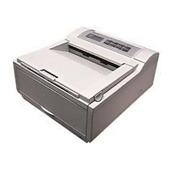
OL400 / 800 / 820 / 830 / 840
Note: This Adobe Acrobat version of the Okidata Service Training Manual was built with the
pictures rendered at 300 dpi, which is ideal for printing, but does not view on most
displays well.
Copyright 1997, Okidata, Division of OKI America, Inc. All rights reserved. See the OKIDATA Business
Partner Exchange (BPX) for any updates to this material. (http://bpx.okidata.com)
LED Page Printers
Adobe Acrobat printable reference
copy of the OKIDATA Service Training Manual.
Service Guide OL400
Chapter 0 About This Manual
09/17/97
Page: 1
Advertisement
Table of Contents
Troubleshooting

Related Manuals for OKIDATA OL400


Summary of Contents for OKIDATA OL400
- Page 1 OKIDATA Service Training Manual. 09/17/97 Note: This Adobe Acrobat version of the Okidata Service Training Manual was built with the pictures rendered at 300 dpi, which is ideal for printing, but does not view on most displays well.
-
Page 2: Table Of Contents
..2.3.06 Main Motor (Drum Motor) ..2.3.07 LED Head ..2.3.08 Resist Motor ..2.3.09 DC Fan 2.4 Mechanical Operation Description ..2.4.02 OL400 Printing Process ..2.4.03 Process Descriptions 2.5 Sensors And Switches ..2.5.01 Sensors and Switches ..2.5.02 Sensor Functions 3 Maintenance & Disassembly 3.1 Maintenance... - Page 3 Table of Contents Page ..3.2.03 Interface Board ..3.2.04 RAM Board (Option) ..3.2.05 Main Controller Board ..3.2.06 Engine Controller Circuit Board (LLAB) ..3.2.07 Main Motor ..3.2.08 DC Fan Assembly ..3.2.09 Idle Gears "A" and "B", and the Reduction Gear ..3.2.10 Power Supply Unit ..3.2.11 Upper Unit ..3.2.12 Fusing Unit ..3.2.13 Backup Roller...
- Page 4 Table of Contents Page ..RAP 07: Light or Blurred Images ..RAP 09: Blank Output ..RAP 10: Vertical Black Stripes ..RAP 11: Repeating Marks ..RAP 12: Blank Spots ..RAP 13: Vertical White Stripes ..RAP 14: Black Page ..RAP 15: Poor Fusing 4.7 Self-Tests A Reference Charts A.1 Overview...
- Page 5 LaserJet and LaserJet+ are registered trademarks of Hewlett Packard Corporation Proprinter is a registered trademark of International Business Machines, Inc. Note: The OL400 Service Training course is part of the OL-Series Training Course and can not be purchased separately. Copyright 1997, Okidata, Division of OKI America, Inc. All rights reserved. See the OKIDATA Business...
-
Page 6: About This Manual
Page: 3 Service Guide OL400 Chapter 0 About This Manual Note: The OL400 Service Training course is part of the OL-Series Training Course and can not be purchased separately. THE OL400/800/820/830/840 VIDEO TRAINING KIT covers the following products: OL400 OL800... -
Page 7: Product Specifications
4 letter-sized sheets per minute. A 512K page memory is standard on the OL400; this can be expanded to 1.5 or 2.5 megabyte with an optional RAM printed circuit board and a memory expansion chip set. Twenty-five resident fonts are included in the OL400 and five optional font cards are currently available. -
Page 8: Physical Specifications
Length: 17.72" 1.2.02 Printer Weight 24 lbs. 1.2.03 LED Array Number of LED Elements - 2560 Copyright 1997, Okidata, Division of OKI America, Inc. All rights reserved. See the OKIDATA Business Partner Exchange (BPX) for any updates to this material. (http://bpx.okidata.com) -
Page 9: Print Specifications
Manual Feed 1.3.06 Paper Delivery Method Face down/face up 1.3.07 Resolution 300 x 300 dots/inch Copyright 1997, Okidata, Division of OKI America, Inc. All rights reserved. See the OKIDATA Business Partner Exchange (BPX) for any updates to this material. (http://bpx.okidata.com) -
Page 10: Paper Specifications
Manual feed / Face up delivery only Must be able to withstand the heat of the fusing process. Copyright 1997, Okidata, Division of OKI America, Inc. All rights reserved. See the OKIDATA Business Partner Exchange (BPX) for any updates to this material. (http://bpx.okidata.com) -
Page 11: Power Requirements
At standby: 43 dB maximum AGENCY APPROVALS FCC Class B UL 478 Ver.5 CSA 22.2 220 Copyright 1997, Okidata, Division of OKI America, Inc. All rights reserved. See the OKIDATA Business Partner Exchange (BPX) for any updates to this material. (http://bpx.okidata.com) -
Page 12: Options
Page: 9 Service Guide OL400 Chapter 1 Product Specifications OPTIONS 1.8.01 RAM Expansion Board 1 megabyte (expands printer memory to 1.5 megabyte) Technician installed 1.8.02 RAM Expansion Chip Set Technician installed 1 megabyte memory expansion chip set used in conjunction with the RAM Expansion Board option. - Page 13 1.8.05 Interface Boards RS-232C Serial Interface Board Centronics Parallel Interface Board Technician installed Copyright 1997, Okidata, Division of OKI America, Inc. All rights reserved. See the OKIDATA Business Partner Exchange (BPX) for any updates to this material. (http://bpx.okidata.com)
-
Page 14: Consumables
One LED Head Cleaning Kit Image Drum Cartridge (P/N 56106601) One Image Drum Cartridge One Ozone Filter Copyright 1997, Okidata, Division of OKI America, Inc. All rights reserved. See the OKIDATA Business Partner Exchange (BPX) for any updates to this material. (http://bpx.okidata.com) -
Page 15: Reliability Data
Approximately 180,000 pages (5 years) 1.10.04 Printer Duty Cycle Approximately 3,000 pages @ 5% print density Copyright 1997, Okidata, Division of OKI America, Inc. All rights reserved. See the OKIDATA Business Partner Exchange (BPX) for any updates to this material. (http://bpx.okidata.com) -
Page 16: Principles Of Operation
Main Control Function Printer Control Function { } Mechanical Operation Sensors and Switches { } Copyright 1997, Okidata, Division of OKI America, Inc. All rights reserved. See the OKIDATA Business Partner Exchange (BPX) for any updates to this material. (http://bpx.okidata.com) -
Page 17: Main Control Function
Interface Control Centronics Parallel Interface Board RS-232C Serial Interface Board Optional Font Card Optional RAM Copyright 1997, Okidata, Division of OKI America, Inc. All rights reserved. See the OKIDATA Business Partner Exchange (BPX) for any updates to this material. (http://bpx.okidata.com) -
Page 18: Centronics Parallel Interface
Upon turning off the BUSY signal, the ACK-N signal is sent to the host interface to acknowledge reception processing. Copyright 1997, Okidata, Division of OKI America, Inc. All rights reserved. See the OKIDATA Business Partner Exchange (BPX) for any updates to this material. (http://bpx.okidata.com) -
Page 19: Rs-232C Serial Interface
The baud rate, character length, parity check, stop bit, etc., are automatically written into the 82C51 from the menu, so hardware switches are not required. Copyright 1997, Okidata, Division of OKI America, Inc. All rights reserved. See the OKIDATA Business Partner Exchange (BPX) for any updates to this material. (http://bpx.okidata.com) -
Page 20: Optional Font Card
In addition to the twenty-five resident fonts, an optional font IC card is available. The CD-N signal detects the option font card. Copyright 1997, Okidata, Division of OKI America, Inc. All rights reserved. See the OKIDATA Business Partner Exchange (BPX) for any updates to this material. (http://bpx.okidata.com) -
Page 21: Optional Ram Board / Ic Set
The expansion RAM board contains 1 Mbyte of memory and sockets for an additional 1 Mbyte. This RAM is in addition to the 512 Kbyte on the Main Control Board. Copyright 1997, Okidata, Division of OKI America, Inc. All rights reserved. See the OKIDATA Business Partner Exchange (BPX) for any updates to this material. (http://bpx.okidata.com) -
Page 22: Printer Control Function
Engine Board Power Supply Unit Fuser Unit Main Motor LED Head Resist Motor DC Fan Copyright 1997, Okidata, Division of OKI America, Inc. All rights reserved. See the OKIDATA Business Partner Exchange (BPX) for any updates to this material. (http://bpx.okidata.com) - Page 23 The operation panel is controlled by the operation panel interface located on the Main Control Board via the Engine Board. Copyright 1997, Okidata, Division of OKI America, Inc. All rights reserved. See the OKIDATA Business Partner Exchange (BPX) for any updates to this material. (http://bpx.okidata.com)
- Page 24 It is reset to zero when the drum is replaced by holding down the RESET button and applying power to the printer. Copyright 1997, Okidata, Division of OKI America, Inc. All rights reserved. See the OKIDATA Business Partner Exchange (BPX) for any updates to this material. (http://bpx.okidata.com)
- Page 25 (LLAB-PCB). It is kept at about -680 vdc during charging. Copyright 1997, Okidata, Division of OKI America, Inc. All rights reserved. See the OKIDATA Business Partner Exchange (BPX) for any updates to this material. (http://bpx.okidata.com)
- Page 26 Upon detecting a fuser alarm, the CPU will halt (after printing the current page). Copyright 1997, Okidata, Division of OKI America, Inc. All rights reserved. See the OKIDATA Business Partner Exchange (BPX) for any updates to this material. (http://bpx.okidata.com)
-
Page 27: Main Motor (Drum Motor)
The main motor is driven by the motor drive IC (M54646). It is a two-phase motor, driven by the DM-PH1 and DM-PH2 signals. Copyright 1997, Okidata, Division of OKI America, Inc. All rights reserved. See the OKIDATA Business Partner Exchange (BPX) for any updates to this material. (http://bpx.okidata.com) -
Page 28: Led Head
The on/off states of the LEDs are controlled by the signals STB1- STB4; 640 bits are turned on or off at a time. Copyright 1997, Okidata, Division of OKI America, Inc. All rights reserved. See the OKIDATA Business Partner Exchange (BPX) for any updates to this material. (http://bpx.okidata.com) -
Page 29: Resist Motor
IC (LB1731). It is four-phase motor, driven according to the RM-H1, RM-H2, and RM ON-P signals. Copyright 1997, Okidata, Division of OKI America, Inc. All rights reserved. See the OKIDATA Business Partner Exchange (BPX) for any updates to this material. (http://bpx.okidata.com) -
Page 30: Dc Fan
The fan is driven for 1 minute after the fuser has been turned off. The fan speed is reduced if the next PRINT signal is not received within 1 minute. Copyright 1997, Okidata, Division of OKI America, Inc. All rights reserved. See the OKIDATA Business Partner Exchange (BPX) for any updates to this material. (http://bpx.okidata.com) -
Page 31: Mechanical Operation Description
Toner that remains on the photoconductive material is returned to the developer. Fusing The toner is fused to the paper using heat and pressure. Copyright 1997, Okidata, Division of OKI America, Inc. All rights reserved. See the OKIDATA Business Partner Exchange (BPX) for any updates to this material. (http://bpx.okidata.com) -
Page 32: Ol400 Printing Process
2.4.02 OL400 Printing Process The layout of the electrostatic printing process hardware is shown below. Copyright 1997, Okidata, Division of OKI America, Inc. All rights reserved. See the OKIDATA Business Partner Exchange (BPX) for any updates to this material. (http://bpx.okidata.com) -
Page 33: Process Descriptions
Page: 29 Service Guide OL400 Chapter 2 Principles of Operation 2.4.03 Process Descriptions Hopping and Feeding Hopping and feeding are accomplished by the resist motor, hopping roller, and resist rollers. Turning the resist motor in the clockwise direction drives the hopping roller. Turning the resist motor in the counter-clockwise direction drives the feed rollers. - Page 34 exceeds -700 vdc, the varistor shunts this excess voltage to ground. Exposure Light emitted from the LED head is radiated to the image drum surface which is charged with negative ions. The areas of the drum that light is directed to become conductive. This allows the surface potential in these areas to drop from -700 vdc to approximately -100 vdc, thereby forming a latent image associated with the image signals.
- Page 35 Paper is ejected from the fuser unit by the back-up roller. If the face-up stacker is closed, paper is routed to the top of the printer for face-down delivery. Copyright 1997, Okidata, Division of OKI America, Inc. All rights reserved. See the OKIDATA Business Partner Exchange (BPX) for any updates to this material. (http://bpx.okidata.com)
-
Page 36: Sensors And Switches
Service Guide OL400 Chapter 2 Principles of Operation SENSORS AND SWITCHES Sensors & Switches Sensor Functions Copyright 1997, Okidata, Division of OKI America, Inc. All rights reserved. See the OKIDATA Business Partner Exchange (BPX) for any updates to this material. (http://bpx.okidata.com) -
Page 37: Sensors And Switches
Page: 31 Service Guide OL400 Chapter 2 Principles of Operation 2.5.01 Sensors and Switches Inlet Sensor (Photosensor) Outlet Sensor (Photosensor) Paper Tray Identification Switches Paper End Sensor (Photosensor) Cover Open Switch... - Page 38 Copyright 1997, Okidata, Division of OKI America, Inc. All rights reserved. See the OKIDATA Business Partner Exchange (BPX) for any updates to this material. (http://bpx.okidata.com)
- Page 39 If the sensor remains on in excess of this time, the controller assumes that an exit jam has occurred and an alarm is generated. Copyright 1997, Okidata, Division of OKI America, Inc. All rights reserved. See the OKIDATA Business Partner Exchange (BPX) for any updates to this material. (http://bpx.okidata.com)
-
Page 40: Maintenance & Disassembly
Cleaning procedures must be performed correctly if high print quality is to be achieved. Copyright 1997, Okidata, Division of OKI America, Inc. All rights reserved. See the OKIDATA Business Partner Exchange (BPX) for any updates to this material. (http://bpx.okidata.com) -
Page 41: Maintenance Tools
Shop Vacuum (with filter for toner) Cloth (soft and lint-free) All-purpose Cleaner Grease (Dow Corning BR2 or equivalent) Copyright 1997, Okidata, Division of OKI America, Inc. All rights reserved. See the OKIDATA Business Partner Exchange (BPX) for any updates to this material. (http://bpx.okidata.com) -
Page 42: Maintenance Precautions
Clear the fuser counter when a new fusing unit is installed. Refer to Section 3.3, Adjustments in this Service Handbook.{ } Copyright 1997, Okidata, Division of OKI America, Inc. All rights reserved. See the OKIDATA Business Partner Exchange (BPX) for any updates to this material. (http://bpx.okidata.com) -
Page 43: Disassembly/Assembly Procedures
This Service Handbook lists the disassembly procedures for major components of the unit. Okidata does NOT recommend disassembling a unit which is operating normally. If you decide to perform disassembly during this training, Okidata recommends that you perform only the disassembly procedures for RSPL items. -
Page 44: Upper Cover
Page: 37 Service Guide OL400 Chapter 3 Maintenance & Disassembly 3.2.01 Upper Cover 1. Turn the power switch and unplug the AC power cord from the outlet and the printer power receptacle at the rear of the printer. 2. Remove the paper tray (1), interface cable (2), and font card (3) (if installed). - Page 45 Lower the upper cover into position. If the cover is not installed properly, paper jams will result. Copyright 1997, Okidata, Division of OKI America, Inc. All rights reserved. See the OKIDATA Business Partner Exchange (BPX) for any updates to this material. (http://bpx.okidata.com)
-
Page 46: Led Head
Page: 38 Service Guide OL400 Chapter 3 Maintenance & Disassembly 3.2.02 LED Head 1. Perform this procedure: 3.2.01{ } 2. Push the two blue lock levers (1) toward the rear of the printer and open the LED holder (2). 3. Lift and remove the image drum cartridge (3). To protect the image drum cartridge, please place it back in the styrofoam shipping package. - Page 47 Copyright 1997, Okidata, Division of OKI America, Inc. All rights reserved. See the OKIDATA Business Partner Exchange (BPX) for any updates to this material. (http://bpx.okidata.com)
-
Page 48: Interface Board
4. Lift the interface board (5) to disconnect it from the control board (6) for removal. Copyright 1997, Okidata, Division of OKI America, Inc. All rights reserved. See the OKIDATA Business Partner Exchange (BPX) for any updates to this material. (http://bpx.okidata.com) -
Page 49: Ram Board (Option)
4. Lift the RAM board to disconnect it from the main controller board (5) for removal. Copyright 1997, Okidata, Division of OKI America, Inc. All rights reserved. See the OKIDATA Business Partner Exchange (BPX) for any updates to this material. (http://bpx.okidata.com) -
Page 50: Main Controller Board
3. Lift the main controller board (2) to disconnect it from the engine control circuit board (3) and remove the main controller board. Copyright 1997, Okidata, Division of OKI America, Inc. All rights reserved. See the OKIDATA Business Partner Exchange (BPX) for any updates to this material. (http://bpx.okidata.com) -
Page 51: Engine Controller Circuit Board (Llab)
Page: 42 Service Guide OL400 Chapter 3 Maintenance & Disassembly 3.2.06 Engine Controller Circuit Board (LLAB) 1. Perform these procedures: 3.2.01{ } 3.2.03{ } 3.2.04{ } 3.2.05{ } 2. Disconnect the cables (1) from connectors J1, J2, and J5. 3. Open the LED holder to allow access to the engine board mounting screw (2) and remove the mounting screw. - Page 52 Q1 (10) from the old board and mount them on the new board. With LLAB Revision 11, Q1 is not installed because the program is masked in the CPU. Copyright 1997, Okidata, Division of OKI America, Inc. All rights reserved. See the OKIDATA Business Partner Exchange (BPX) for any updates to this material. (http://bpx.okidata.com)
-
Page 53: Main Motor
Page: 43 Service Guide OL400 Chapter 3 Maintenance & Disassembly 3.2.07 Main Motor 1. Perform these procedures: 3.2.01{ } 3.2.03{ } 3.2.04{ } 3.2.05{ } 3.2.06{ } 2. Remove the three mounting screws (1) and detach the shield frame (2). - Page 54 Copyright 1997, Okidata, Division of OKI America, Inc. All rights reserved. See the OKIDATA Business Partner Exchange (BPX) for any updates to this material. (http://bpx.okidata.com)
-
Page 55: Dc Fan Assembly
2. Detach the shield frame (3.2.07 step 6). 3. Remove the DC fan assembly (1). Copyright 1997, Okidata, Division of OKI America, Inc. All rights reserved. See the OKIDATA Business Partner Exchange (BPX) for any updates to this material. (http://bpx.okidata.com) -
Page 56: Idle Gears "A" And "B", And The Reduction Gear
2. Detach the gears in the following order: idle gear "B" (1), reduction gear (2) and idle gear "A" (3). Copyright 1997, Okidata, Division of OKI America, Inc. All rights reserved. See the OKIDATA Business Partner Exchange (BPX) for any updates to this material. (http://bpx.okidata.com) -
Page 57: Power Supply Unit
Page: 46 Service Guide OL400 Chapter 3 Maintenance & Disassembly 3.2.10 Power Supply Unit 1. Perform these procedures: 3.2.01{ } 3.2.03{ } 3.2.04{ } 3.2.05{ } 3.2.06{ } 3.2.07{ } 2. Disconnect the two high-voltage cables (1). NOTE: When installing, the cables are keyed for correct placement. The larger connector is to the front of the printer. - Page 58 Copyright 1997, Okidata, Division of OKI America, Inc. All rights reserved. See the OKIDATA Business Partner Exchange (BPX) for any updates to this material. (http://bpx.okidata.com)
-
Page 59: Upper Unit
Page: 47 Service Guide OL400 Chapter 3 Maintenance & Disassembly 3.2.11 Upper Unit 1. Perform these procedures: 3.2.01{ } 3.2.02{ } 3.2.03{ } 3.2.04{ } 3.2.05{ } 3.2.06{ } 3.2.07{ } 3.2.08{ } 3.2.10{ } 2. Place the face-up stacker assembly, located at the rear of the printer, down. Then, lift the upper unit. - Page 60 Be careful not to drop the fulcrum block (6) and the idle gear (7) when removing the upper unit. Copyright 1997, Okidata, Division of OKI America, Inc. All rights reserved. See the OKIDATA Business Partner Exchange (BPX) for any updates to this material. (http://bpx.okidata.com)
-
Page 61: Fusing Unit
Page: 48 Service Guide OL400 Chapter 3 Maintenance & Disassembly 3.2.12 Fusing Unit WARNING: Allow the printer to cool before servicing the fusing unit. 1. Perform these procedures: 3.2.01{ } 3.2.02{ } 3.2.03{ } 3.2.04{ } 3.2.05{ } 3.2.06{ } 3.2.07{ }... - Page 62 The four separator claws must move freely within their grooves or paper jams will result. Copyright 1997, Okidata, Division of OKI America, Inc. All rights reserved. See the OKIDATA Business Partner Exchange (BPX) for any updates to this material. (http://bpx.okidata.com)
-
Page 63: Backup Roller
3. Use a straight slot screwdriver to detach the sheet guide (2). 4. Remove the backup roller (3). Copyright 1997, Okidata, Division of OKI America, Inc. All rights reserved. See the OKIDATA Business Partner Exchange (BPX) for any updates to this material. (http://bpx.okidata.com) -
Page 64: Transfer Charger Assembly
6. Lift and remove the transfer charger assembly. Copyright 1997, Okidata, Division of OKI America, Inc. All rights reserved. See the OKIDATA Business Partner Exchange (BPX) for any updates to this material. (http://bpx.okidata.com) -
Page 65: Resist Roller Assembly
The left claw can be accessed from the bottom of the printer. 3. Lift the resist roller assembly from the printer. Copyright 1997, Okidata, Division of OKI America, Inc. All rights reserved. See the OKIDATA Business Partner Exchange (BPX) for any updates to this material. (http://bpx.okidata.com) -
Page 66: Idle Gear C
The cutout (3) on the post should be positioned to the left side of the printer and on the top when installing. Copyright 1997, Okidata, Division of OKI America, Inc. All rights reserved. See the OKIDATA Business Partner Exchange (BPX) for any updates to this material. (http://bpx.okidata.com) -
Page 67: Paper Supply Unit
5. Lift the paper supply assembly (6) at its front until the frame of the unit comes off the guide pins, then move the unit towards you for removal. Copyright 1997, Okidata, Division of OKI America, Inc. All rights reserved. See the OKIDATA Business Partner Exchange (BPX) for any updates to this material. (http://bpx.okidata.com) -
Page 68: Resist Motor
3.2.17{ } 2. Remove the two mounting screws (1). 3. Detach the resist motor (2). Copyright 1997, Okidata, Division of OKI America, Inc. All rights reserved. See the OKIDATA Business Partner Exchange (BPX) for any updates to this material. (http://bpx.okidata.com) -
Page 69: Engine Connection Board
3. On the paper supply unit, press the pointed end of the nylon latch (2), push out the head (3), and remove the latch. 4. Detach the engine connection board (4). Copyright 1997, Okidata, Division of OKI America, Inc. All rights reserved. See the OKIDATA Business Partner Exchange (BPX) for any updates to this material. (http://bpx.okidata.com) -
Page 70: Hopping Roller
Page: 56 Service Guide OL400 Chapter 3 Maintenance & Disassembly 3.2.20 Hopping Roller 1. Perform these procedures: 3.2.01{ } 3.2.02{ } 3.2.03{ } 3.2.04{ } 3.2.05{ } 3.2.15{ } 3.2.17{ } 2. Remove the two screws (1) and slide the upper plate assembly (2) until the claws (3) are unlocked. - Page 71 When installing, always mount the hopping roller shaft above the ground plate, which is on the left side of the printer. Copyright 1997, Okidata, Division of OKI America, Inc. All rights reserved. See the OKIDATA Business Partner Exchange (BPX) for any updates to this material. (http://bpx.okidata.com)
-
Page 72: Separator
2. Hold the separator (1) down and remove the escape lever (2) from the pins on the paper supply unit. Be careful not to lose the separator spring (3). Copyright 1997, Okidata, Division of OKI America, Inc. All rights reserved. See the OKIDATA Business Partner Exchange (BPX) for any updates to this material. (http://bpx.okidata.com) -
Page 73: Ozone Filter
Remove the ozone filter (2) from the fan cover. Copyright 1997, Okidata, Division of OKI America, Inc. All rights reserved. See the OKIDATA Business Partner Exchange (BPX) for any updates to this material. (http://bpx.okidata.com) -
Page 74: Adjustments And Service Checks
2. Raise the upper unit. 3. Remove the image drum cartridge. 4. Override the cover open interlock switch. Copyright 1997, Okidata, Division of OKI America, Inc. All rights reserved. See the OKIDATA Business Partner Exchange (BPX) for any updates to this material. (http://bpx.okidata.com) -
Page 75: Actual Page Count
(refer to 3.3.02) Example Actual Page Counter = 235 pages Copyright 1997, Okidata, Division of OKI America, Inc. All rights reserved. See the OKIDATA Business Partner Exchange (BPX) for any updates to this material. (http://bpx.okidata.com) -
Page 76: Modified Page Count
The number "0" is represented by 10 flashes The Actual and Modified Page Counters CANNOT be changed. Copyright 1997, Okidata, Division of OKI America, Inc. All rights reserved. See the OKIDATA Business Partner Exchange (BPX) for any updates to this material. (http://bpx.okidata.com) -
Page 77: Vertical Print Start Position Adjustment
General Information The Vertical Print Start Position Adjustment is used to set the top of form position. Use this adjustment to correct print start variations between different OL400 printers, or to achieve a 4.6 mm vertical start position, the default value. - Page 78 +1.0 -3.0 +1.5 -2.5 +2.0 -2.0 +2.5 -1.5 +3.0 -1.0 +3.5 -0.5 Copyright 1997, Okidata, Division of OKI America, Inc. All rights reserved. See the OKIDATA Business Partner Exchange (BPX) for any updates to this material. (http://bpx.okidata.com)
-
Page 79: Setting The Led Head Drive Time
Page: 63 Service Guide OL400 Chapter 3 Maintenance & Disassembly 3.3.05 Setting the LED Head Drive Time General Information This adjustment is necessary only when replacing the LED head. However, if the luminous energy ratings of the new and original LED heads are the same, adjustment is not necessary. The luminous energy rating is on the label on the LED head. - Page 80 21 22 23 24 25 26 27 28 29 30 31 32 33 34 35 36 Copyright 1997, Okidata, Division of OKI America, Inc. All rights reserved. See the OKIDATA Business Partner Exchange (BPX) for any updates to this material. (http://bpx.okidata.com)
-
Page 81: Voltage Adjustment (+5 Vdc)
If adjustment is required, remove the font guide. Change the output voltage by adjusting potentiometer RV1 on the power supply board (2). Copyright 1997, Okidata, Division of OKI America, Inc. All rights reserved. See the OKIDATA Business Partner Exchange (BPX) for any updates to this material. (http://bpx.okidata.com) -
Page 82: Darkness Control
4. Press "+" to toggle through the values until the desired setting is reached. 5. Press ENTER/MENU RESET to store the new setting. Copyright 1997, Okidata, Division of OKI America, Inc. All rights reserved. See the OKIDATA Business Partner Exchange (BPX) for any updates to this material. (http://bpx.okidata.com) -
Page 83: Cleaning
Page: 66 Service Guide OL400 Chapter 3 Maintenance & Disassembly CLEANING 3.4.01 General Information Remove any dropped toner and dust. Clean inside and around the printer with a vacuum cleaner when necessary. CAUTION: Do not touch the image drum, the LED head, or the LED head connector block. - Page 84 Copyright 1997, Okidata, Division of OKI America, Inc. All rights reserved. See the OKIDATA Business Partner Exchange (BPX) for any updates to this material. (http://bpx.okidata.com)
-
Page 85: Failure & Repair Analysis
Output Samples Repair Analysis Procedures* Tests Continuous Print Print Fonts Menu Print Serial Interface Loop Engine Copyright 1997, Okidata, Division of OKI America, Inc. All rights reserved. See the OKIDATA Business Partner Exchange (BPX) for any updates to this material. (http://bpx.okidata.com) -
Page 86: Troubleshooting Updates
Technical Service Bulletins 4.2.02 Okilink II Okilink II is Okidata's Bulletin Board Service. This service is available to all Okidata Certified Service Technicians. Okilink II provides troubleshooting and service information. Technicians can download files, ask questions of Okidata's technical support personnel, and participate in round table discussions about Okidata products and services. -
Page 87: Reporting Problems
Errors and corrections in the training materials are listed in the Training Section of Okilink II. The Technical Service Bulletins (also known as Okidata's Monthly Mail) are available via Okilink II. Situations that are not addressed in the reference documentation, technical service bulletins, or round tables may be reported to the Dealer Service and Support Engineers (DSSEs) or the Technical Training Group. - Page 88 Firmware Revision Level Description of Problem Document Name (with page number or procedure) with error or problem. Copyright 1997, Okidata, Division of OKI America, Inc. All rights reserved. See the OKIDATA Business Partner Exchange (BPX) for any updates to this material. (http://bpx.okidata.com)
-
Page 89: Troubleshooting Tips
4. Do not expose the image drum to light for more than 5 minutes. Copyright 1997, Okidata, Division of OKI America, Inc. All rights reserved. See the OKIDATA Business Partner Exchange (BPX) for any updates to this material. (http://bpx.okidata.com) -
Page 90: Fault Alarms
If the printer output is faulty, refer to the Output Samples and determine which example resembles the problem. Proceed to the Repair Analysis Procedure (RAP) referred to by the example. Copyright 1997, Okidata, Division of OKI America, Inc. All rights reserved. See the OKIDATA Business Partner Exchange (BPX) for any updates to this material. (http://bpx.okidata.com) -
Page 91: Error Messages Table
Page: 72 Service Guide OL400 Chapter 4 Failure & Repair Analysis 4.5.02 Error Messages Table LCD Error Message Message Description Recommended Action ON-LINE Ready to receive data in Normal Operation on-line mode OFF-LINE Printer idling in off-line mode Normal Operation... - Page 92 FONT CARD FONT The font card is not recognized Install card NOT FOUND by the printer properly or replace main controller ERROR FONT CARD Font card taken out during Printer must be REMOVED ON-LINE on-line OFF-LINE when changing font card ERROR PRINT Printing overrun Page layout too...
- Page 93 ERROR ENGINE Engine fan motor error Replace DC Fan FAN PROBLEM or engine controller ERROR ENGINE Engine error other than the Refer to RAP 06 above two WARMING UP Power has been turned on and Normal Operation now warming up. PAPER OUT TRAY Paper cassette has run out of Add paper to...
- Page 94 Drum life has been attained Replace Drum Kit. Press RECOVER when turning the printer ON Copyright 1997, Okidata, Division of OKI America, Inc. All rights reserved. See the OKIDATA Business Partner Exchange (BPX) for any updates to this material. (http://bpx.okidata.com)
- Page 95 Page: 73 Service Guide OL400 Chapter 4 Failure & Repair Analysis 4.5.03 Output Samples ###### Copyright 1997, Okidata, Division of OKI America, Inc. All rights reserved. See the OKIDATA Business Partner Exchange (BPX) for any updates to this material. (http://bpx.okidata.com)
-
Page 96: Repair Analysis Procedures
3. All of the RAPs will begin with a START Statement, followed by questions or another type of statement. 4. If the RAPs do not lead you to the cause of a problem, please report this to Okidata. Refer to Section 4.3 for further details{ Copyright 1997, Okidata, Division of OKI America, Inc. -
Page 97: Rap Index
RECOVER switch. DO NOT RESET THE DRUM COUNTER unless you replace the image drum cartridge. Copyright 1997, Okidata, Division of OKI America, Inc. All rights reserved. See the OKIDATA Business Partner Exchange (BPX) for any updates to this material. (http://bpx.okidata.com) -
Page 98: Rap 01Printer Does Not Initialize
Page: 76 Service Guide OL400 Chapter 4 Failure & Repair Analysis RAP 01Printer Does Not Initialize START Turn the power OFF, then ON. Is the WARMING UP message displayed? Go to B Check the AC cable connection. Verify that +5V output is generated. Check the connection at the main controller circuit board... - Page 99 Allow the unit to warm up and go ON-LINE. Replace the engine controller circuit board Copyright 1997, Okidata, Division of OKI America, Inc. All rights reserved. See the OKIDATA Business Partner Exchange (BPX) for any updates to this material. (http://bpx.okidata.com)
-
Page 100: Rap 02:Paper Feed Jam Alarm
Run the Engine Drive Test. Does the resist roller turn? Replace the paper feed assembly. Replace the engine controller board. Copyright 1997, Okidata, Division of OKI America, Inc. All rights reserved. See the OKIDATA Business Partner Exchange (BPX) for any updates to this material. (http://bpx.okidata.com) -
Page 101: Rap 03:Paper Jam Alarm
Page: 78 Service Guide OL400 Chapter 4 Failure & Repair Analysis RAP 03:Paper Jam Alarm START Does the paper jam occur when the power is turned ON? Go to A Is the paper at the resist or exit sensor? Remove the paper. - Page 102 Check the exit sensor lever for normal operation. Check the paper path for obstructions or replace the engine controller circuit board. Copyright 1997, Okidata, Division of OKI America, Inc. All rights reserved. See the OKIDATA Business Partner Exchange (BPX) for any updates to this material. (http://bpx.okidata.com)
-
Page 103: Rap 04:Size Tray Error Alarm
Is the tray identified correctly? Replace the engine connection board or the engine controller circuit board. Copyright 1997, Okidata, Division of OKI America, Inc. All rights reserved. See the OKIDATA Business Partner Exchange (BPX) for any updates to this material. (http://bpx.okidata.com) -
Page 104: Rap 05:Engine Error - Fusing Problem Alarm
Page: 80 Service Guide OL400 Chapter 4 Failure & Repair Analysis RAP 05:Engine Error - Fusing Problem Alarm START Turn the power OFF, then ON. Does a fuser unit alarm occur immediately? Go to A Is the thermistor open (the normal resistance should be about 100k ohms at room temperature)? Measure between pins 1 and 2 of the cable connected to engine controller circuit board J2. - Page 105 Copyright 1997, Okidata, Division of OKI America, Inc. All rights reserved. See the OKIDATA Business Partner Exchange (BPX) for any updates to this material. (http://bpx.okidata.com)
-
Page 106: Rap 06:Engine Error Alarm
Replace the ROM (Q1) on the engine controller circuit board. Has the trouble been resolved? Replace the engine controller circuit board. Copyright 1997, Okidata, Division of OKI America, Inc. All rights reserved. See the OKIDATA Business Partner Exchange (BPX) for any updates to this material. (http://bpx.okidata.com) -
Page 107: Rap 07:Light Or Blurred Images
Is the problem removed? Replace the Engine Controller Board. Is the problem resolved? Replace the High Voltage Power Supply Unit. Copyright 1997, Okidata, Division of OKI America, Inc. All rights reserved. See the OKIDATA Business... - Page 108 Partner Exchange (BPX) for any updates to this material. (http://bpx.okidata.com)
-
Page 109: Rap 09:Blank Output
Has the trouble been removed? Replace the LED head. Has the trouble been removed? Replace the image drum cartridge. Copyright 1997, Okidata, Division of OKI America, Inc. All rights reserved. See the OKIDATA Business Partner Exchange (BPX) for any updates to this material. (http://bpx.okidata.com) -
Page 110: Rap 10:Vertical Black Stripes
Has the trouble been removed? Replace the LED head. Has the trouble been removed? Replace the engine controller board. Copyright 1997, Okidata, Division of OKI America, Inc. All rights reserved. See the OKIDATA Business Partner Exchange (BPX) for any updates to this material. (http://bpx.okidata.com) -
Page 111: Rap 11:Repeating Marks
Check/replace the image drum cartridge. 4.75" Check/replace the hopping roller. All others Check/replace the resist rollers. Copyright 1997, Okidata, Division of OKI America, Inc. All rights reserved. See the OKIDATA Business Partner Exchange (BPX) for any updates to this material. (http://bpx.okidata.com) -
Page 112: Rap 12:Blank Spots
Has the trouble been resolved? Replace the high voltage power supply unit. Copyright 1997, Okidata, Division of OKI America, Inc. All rights reserved. See the OKIDATA Business Partner Exchange (BPX) for any updates to this material. (http://bpx.okidata.com) -
Page 113: Rap 13:Vertical White Stripes
Replace the image drum cartridge. Power ON the printer power while pressing RECOVER switch to clear the drum counter. Copyright 1997, Okidata, Division of OKI America, Inc. All rights reserved. See the OKIDATA Business Partner Exchange (BPX) for any updates to this material. (http://bpx.okidata.com) -
Page 114: Rap 14:Black Page
Replace the image drum cartridge. Power ON while pressing the RECOVER switch to clear the drum counter. Copyright 1997, Okidata, Division of OKI America, Inc. All rights reserved. See the OKIDATA Business Partner Exchange (BPX) for any updates to this material. (http://bpx.okidata.com) -
Page 115: Rap 15:Poor Fusing
Replace the fuser assembly. Has the trouble been removed? Replace the engine controller circuit board. Copyright 1997, Okidata, Division of OKI America, Inc. All rights reserved. See the OKIDATA Business Partner Exchange (BPX) for any updates to this material. (http://bpx.okidata.com) -
Page 116: Self-Tests
Serial Interface Loop Test Engine Test 4.7.02 Continuous Print Test During the Continuous Print Test the OL400 will print a rolling ASCII character set. This test is helpful in determining the relative print quality of an entire page. 4.7.03 Print Fonts Although Print Fonts is not usually considered a diagnostic, it is quite useful in determining if the OL400 is recognizing Font Cards and DLL Fonts. - Page 117 7. To stop the test, press Switch 1. 8. The printer may print a few more pages before stopping the test. Copyright 1997, Okidata, Division of OKI America, Inc. All rights reserved. See the OKIDATA Business Partner Exchange (BPX) for any updates to this material. (http://bpx.okidata.com)
-
Page 118: Overview
Sensors Test Points Where an item is not applicable, the word NONE will be listed. Copyright 1997, Okidata, Division of OKI America, Inc. All rights reserved. See the OKIDATA Business Partner Exchange (BPX) for any updates to this material. (http://bpx.okidata.com) -
Page 119: Charts
Page: 92 Service Guide OL400 Chapter A Reference Charts A.2 CHARTS Index to Charts Description Board Designation Section Main Controller LBPE / LBPF A.2.01{ } Engine Controller LLAB A.2.02{ } Operator Panel LLDC A.2.03{ } Engine Connection LLCC A.2.04{ }... - Page 120 Copyright 1997, Okidata, Division of OKI America, Inc. All rights reserved. See the OKIDATA Business Partner Exchange (BPX) for any updates to this material. (http://bpx.okidata.com)
-
Page 121: Main Controller Board (Lbpe / Lbpf)
Page: 93 Service Guide OL400 Chapter A Reference Charts A.2.01 Main Controller Board (LBPE / LBPF) Firmware O4B - PROM (512K) - Program O5B - PROM (512K) - Program 07C-Masked ROM (4Mbit) - Resident Fonts Fuses NONE Jumpers NONE Sensors... - Page 122 Paper Deliver Units are interchangeable between both A and B revisions of the OL400.Revision A Program ROMs are 04B (PN31060501), 05B (PN31060601), Self-Test 2.22. Copyright 1997, Okidata, Division of OKI America, Inc. All rights reserved. See the OKIDATA Business Partner Exchange (BPX) for any updates to this material. (http://bpx.okidata.com)
-
Page 123: Engine Controller Board (Llab)
Page: 94 Service Guide OL400 Chapter A Reference Charts A.2.02 Engine Controller Board (LLAB) Firmware Q1 - EPROM (64Kbyte) - Engine Control Beginning with LLAB Revision 11, Q1 is not needed. The Q1 ROM has been changed to Masked ROM internal to MPU 83C154, which replaces MPU 80C51. - Page 124 +38vdc J6 pin 15 (Power Supply) +5vdc J6 pins 13,31,32 (Power Supply) Ground - J6 pin 16 Copyright 1997, Okidata, Division of OKI America, Inc. All rights reserved. See the OKIDATA Business Partner Exchange (BPX) for any updates to this material. (http://bpx.okidata.com)
-
Page 125: Operator Panel Pcb (Lldc)
A.2.03 Operator Panel PCB (LLDC) Firmware NONE Fuses NONE Jumpers NONE Sensors NONE Switches NONE Test Points NONE Copyright 1997, Okidata, Division of OKI America, Inc. All rights reserved. See the OKIDATA Business Partner Exchange (BPX) for any updates to this material. (http://bpx.okidata.com) -
Page 126: Engine Connection Pcb (Llcc)
Chapter A Reference Charts A.2.04 Engine Connection PCB (LLCC) Firmware NONE Fuses NONE Jumpers NONE Sensors Paper-End Sensor Switches Paper Tray identification switches Test Points NONE Copyright 1997, Okidata, Division of OKI America, Inc. All rights reserved. See the OKIDATA Business... - Page 127 Partner Exchange (BPX) for any updates to this material. (http://bpx.okidata.com)
-
Page 128: Centronics Parallel Interface Pcb (Llcp / Llcq)
Page: 97 Service Guide OL400 Chapter A Reference Charts A.2.05 Centronics Parallel Interface PCB (LLCP / LLCQ) Firmware NONE Fuses NONE Jumpers NONE Sensors NONE Switches S1- Installed : +5vdc on CN5 Pin 18 Test Points NONE... - Page 129 Copyright 1997, Okidata, Division of OKI America, Inc. All rights reserved. See the OKIDATA Business Partner Exchange (BPX) for any updates to this material. (http://bpx.okidata.com)
-
Page 130: Rs-232C Interface Pcb (Llrs)
Page: 98 Service Guide OL400 Chapter A Reference Charts A.2.06 RS-232C Interface PCB (LLRS) Firmware NONE Fuses NONE Jumpers NONE Sensors NONE Switches NONE Test Points NONE... - Page 131 Copyright 1997, Okidata, Division of OKI America, Inc. All rights reserved. See the OKIDATA Business Partner Exchange (BPX) for any updates to this material. (http://bpx.okidata.com)
-
Page 132: Expansion Ram Board (Optional) (Ramk / Ramh)
A.2.07 Expansion RAM Board (optional) (RAMK / RAMH) Firmware NONE Fuses NONE Jumpers NONE Sensors NONE Switches NONE Test Points NONE Copyright 1997, Okidata, Division of OKI America, Inc. All rights reserved. See the OKIDATA Business Partner Exchange (BPX) for any updates to this material. (http://bpx.okidata.com) -
Page 133: Power Interconnect Board (Llie)
A.2.08 Power Interconnect Board (LLIE) Firmware NONE Fuses NONE Jumpers NONE Sensors NONE Jumpers NONE Testpoints NONE Copyright 1997, Okidata, Division of OKI America, Inc. All rights reserved. See the OKIDATA Business Partner Exchange (BPX) for any updates to this material. (http://bpx.okidata.com) -
Page 134: Power Supply Unit
Page: 101 Service Guide OL400 Chapter A Reference Charts A.2.09 Power Supply Unit Fuses F1: AC Line Fuse (125V 8A) F2: +38 V Line Fuse (125V 2.5A) Firmware NONE Jumpers NONE Sensors NONE Switches Cover Interlock Switch Testpoints: +5V CN1 pins 13,31,32... - Page 135 Copyright 1997, Okidata, Division of OKI America, Inc. All rights reserved. See the OKIDATA Business Partner Exchange (BPX) for any updates to this material. (http://bpx.okidata.com)
-
Page 136: B Illustrated Parts Listing
The format for this appendix is a series of tables with diagrams. The table contains the item reference number, the part description, and the Okidata part number. Also note that some items are only available as assemblies. Every effort has been made to clearly indicate which items are in assemblies and which are not. -
Page 137: Illustrated Parts Listing
A consumable is a supply item which has a specified life and needs to be replaced periodically. It is purchased and installed by the end user. Okidata machines are designed to work exclusively with Okidata consumables. By using genuine Okidata consumable products, the investment made in the equipment will be protected. -
Page 138: Parts Ordering Information
Orders are placed through Okidata's Logistics Department. When a technician has successfully completed a product certification course and the Dealer has become service authorized, an information package will be provided to the Dealer. The Okidata Service Center Reference Guide outlines the following. - Page 139 Copyright 1997, Okidata, Division of OKI America, Inc. All rights reserved. See the OKIDATA Business Partner Exchange (BPX) for any updates to this material. (http://bpx.okidata.com)
-
Page 140: Charts
Items 17 - 27, and 41 B.2.03{ } Items 28 - 35 B.2.04{ } Items 36 - 40 B.2.05{ } Copyright 1997, Okidata, Division of OKI America, Inc. All rights reserved. See the OKIDATA Business Partner Exchange (BPX) for any updates to this material. (http://bpx.okidata.com) -
Page 141: B.2.01 Items 1 - 7
Page: 106 Service Guide OL400 Chapter B Illustrated Parts Listing B.2.01 Items 1 - 7 Part numbers are subject to change. Refer to Section B.1.01{ } for finding current information. Item Part Description Okidata Part Number Paper Cassette (Letter Size) - Page 142 Ozone Filter 55503501 Face-up Stacker Assembly 50066601 Copyright 1997, Okidata, Division of OKI America, Inc. All rights reserved. See the OKIDATA Business Partner Exchange (BPX) for any updates to this material. (http://bpx.okidata.com)
-
Page 143: Items
Page: 107 Service Guide OL400 Chapter B Illustrated Parts Listing B.2.02 Items 8 - 16 Part numbers are subject to change. Refer to Section B.1.01 { } for finding current information. Item Part Description Okidata Part Number LED Head 55619501... - Page 144 12 13 14 15 & 16) 240vac Upper Unit (includes #8 9 50213702 12 13 14 15 & 16) Copyright 1997, Okidata, Division of OKI America, Inc. All rights reserved. See the OKIDATA Business Partner Exchange (BPX) for any updates to this material. (http://bpx.okidata.com)
- Page 145 Page: 108 Service Guide OL400 Chapter B Illustrated Parts Listing B.2.03 Items 17 - 27, and 41 Part numbers are subject to change. Refer to Section B.1.01 { }for finding current information. Item Part Description Okidata Part Number Main Pulse Motor...
- Page 146 Idle Gear (in base) 51218601 Post 53329501 Backup Roller Pressure Spring 50914801 DC Fan Assembly 56507601 Copyright 1997, Okidata, Division of OKI America, Inc. All rights reserved. See the OKIDATA Business Partner Exchange (BPX) for any updates to this material. (http://bpx.okidata.com)
-
Page 147: Items
Page: 109 Service Guide OL400 Chapter B Illustrated Parts Listing B.2.04 Items 28 - 35 Part numbers are subject to change. Refer to Section B.1.01 { } for finding current information. Item Part Description Okidata Part Number Power Supply Unit (120Volts) - Page 148 Three Main Controller Boards are available. See Appendix A { } for information on installing the correct board. Copyright 1997, Okidata, Division of OKI America, Inc. All rights reserved. See the OKIDATA Business Partner Exchange (BPX) for any updates to this material. (http://bpx.okidata.com)
- Page 149 Page: 110 Service Guide OL400 Chapter B Illustrated Parts Listing B.2.05 Items 36 - 40 Item Part Description Okidata Part Number Engine Connection Board (LLCC PCB) 55044601 Resist Motor (70 Ohms) 56507401 Resist Motor (79 Ohms) 56507402 Separator 53500501 Hopping Roller (includes 2 pins)
- Page 150 Part numbers are subject to change. Refer to Section B.1.01 { } for finding current information. Copyright 1997, Okidata, Division of OKI America, Inc. All rights reserved. See the OKIDATA Business Partner Exchange (BPX) for any updates to this material. (http://bpx.okidata.com)
Need help?
Do you have a question about the OL400 and is the answer not in the manual?
Questions and answers