Advertisement
Advertisement
Table of Contents

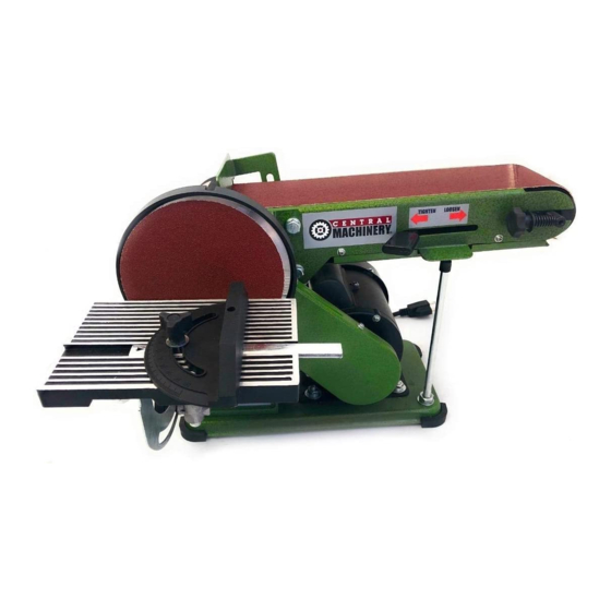
Summary of Contents for Central Machinery 97181
-
Page 2: Table Of Contents
4. DON’T USE IN DANGEROUS ENVIRONMENT. to do a job for which it was not designed. Don’t use power tools in damp or wet locations, or expose them to rain. Keep work area well lighted. Page 2 For technical questions, please call 1-800-444-3353. Item 97181... - Page 3 It’s safer than using your hand and it frees both hands to operate tool. 21. NEVER LEAVE TOOL RUNNING UNATTENDED. TURN POWER OFF. Don’t leave tool until it comes to a complete stop. Item 97181 For technical questions, please call 1-800-444-3353. Page 3...
-
Page 4: Sander Safety Warnings
Switch when the tool is not in use. pulled into the machine. For safety, it must be adjusted very close to the sanding surface. Page 4 For technical questions, please call 1-800-444-3353. Item 97181... -
Page 5: Vibration Safety
If you feel any medical or physical symptoms related to vibration (such as tingling, numbness, and white or blue fingers), seek medical advice as soon as possible. SAVE THESE INSTRUcTIONS. Item 97181 For technical questions, please call 1-800-444-3353. Page 5... -
Page 6: Specifications
Drive Axle (54). See Figure B. Set Screw (6) Rubber Feet (28) Drive Axle (54) Backing Disc (5) Figure A Figure B 3. Tighten the Set Screw (6) securely. Page 6 For technical questions, please call 1-800-444-3353. Item 97181... - Page 7 Insert the Safety Key into the Switch. This “Key” is a safety precaution and should remain in the Switch during use and be removed after Switch (31) is turned off and/or any time the Belt/Disc Sander is left unattended or in storage. Item 97181 For technical questions, please call 1-800-444-3353.
-
Page 8: Operation
Flat Side (76) See Figure E and Figure F. Figure G 5. Tighten all fasteners. Make sure the Pivot Indicator (70) operates smoothly when the Angle Adjusting Knob (75) is loosened. Page 8 For technical questions, please call 1-800-444-3353. Item 97181... - Page 9 Adjusting the Sanding Belt Tracking 1. With the Belt/Disc Sander turned off, 2. If the belt starts moving to the side of manually move the Sanding Belt. either roller, it needs to be adjusted. Item 97181 For technical questions, please call 1-800-444-3353. Page 9...
-
Page 10: General Operating Instructions
Sanding Disc (as you face it) to sand. The Sanding Disc turns counterclockwise and using the right side could cause kickback. Page 10 For technical questions, please call 1-800-444-3353. Item 97181... -
Page 11: Maintenance
Then, wipe external surfaces of the tool with clean cloth. WARNING! If the supply cord of this power tool is damaged, it must be replaced only by a qualified service technician. Item 97181 For technical questions, please call 1-800-444-3353. Page 11... -
Page 12: Sanding Belt Replacement
Motor (40) further forward towards Front Roller (44), Replace Backing Disc and tighten Set Screws. making sure to pull evenly on the motor. While holding the Motor in its current position, tighten the Nuts. Page 12 For technical questions, please call 1-800-444-3353. Item 97181... -
Page 13: Troubleshooting
2. Too much pressure. 2. Use less pressure. Follow all safety precautions whenever diagnosing or servicing the tool. Disconnect power supply before service. Item 97181 For technical questions, please call 1-800-444-3353. Page 13... -
Page 14: Parts List And Diagram
If product has no serial number, record month and year of purchase instead. Note: Some parts are listed and shown for illustration purposes only, Some parts are listed and shown for illustration purposes only, and are not available individually as replacement parts. Page 14 For technical questions, please call 1-800-444-3353. Item 97181... -
Page 15: Assembly Diagram
Assembly Diagram Item 97181 For technical questions, please call 1-800-444-3353. Page 15... -
Page 16: Warranty
Limited 90 Day Warranty Harbor Freight Tools Co. makes every effort to assure that its products meet high quality and durability standards, and warrants to the original purchaser that this product is free from defects in materials and workmanship for the period of 90 days from the date of purchase.


Need help?
Do you have a question about the 97181 and is the answer not in the manual?
Questions and answers
part number and cost for Central Machinery belt and sander disc. for the disc only
The Central Machinery 97181 belt and disc sander was mentioned with a price of $76 in the first document. Additionally, a used unit was listed for $63 on eBay.
This answer is automatically generated