Table of Contents

Related Manuals for BenQ A31


Summary of Contents for BenQ A31
- Page 1 Release 1.0 Service Manual Level 1-3 Release Date Department Notes to change R 1.0 28.12.2005 BenQ Mobile S CC CES New document 10/2005 Technical Documentation TD_Repair_L2.5L_A31_R1.0.pdf Page 1 of 46 Company Confidential 2005©BenQ...
-
Page 2: Table Of Contents
10 JPICS (Java based Product Information Controlling System) ..........23 11 International Mobile Equipment Identity, IMEI..............29 12 General Testing Information....................30 13 Introduction of Service Repair Documentation for Level 3 Basic Repairs – A31....36 14 List of available Level 3 Basic Parts..................37 15 Hardware Requirements ......................37 16 A31 Board Layout........................38... -
Page 3: Key Feature
Speed dialing keys, Programmable soft keys Handsfree talking Alarm function Calculator Stopwatch Silent alert (Vibra) External Antenna Connector in the phone offers an interface for a built-in car kit 10/2005 Technical Documentation TD_Repair_L2.5L_A31_R1.0.pdf Page 3 of 46 Company Confidential 2005©BenQ... -
Page 4: A31 Interface To Accessories
Release 1.0 2 A31 Interface to Accessories The car cradle is the same design of the G85 existing design. Nano I/O connector is for G85 generation. The compatible interface is suitable to use the travel charger. 10/2005 Technical Documentation TD_Repair_L2.5L_A31_R1.0.pdf... -
Page 5: Unit Description Of A31
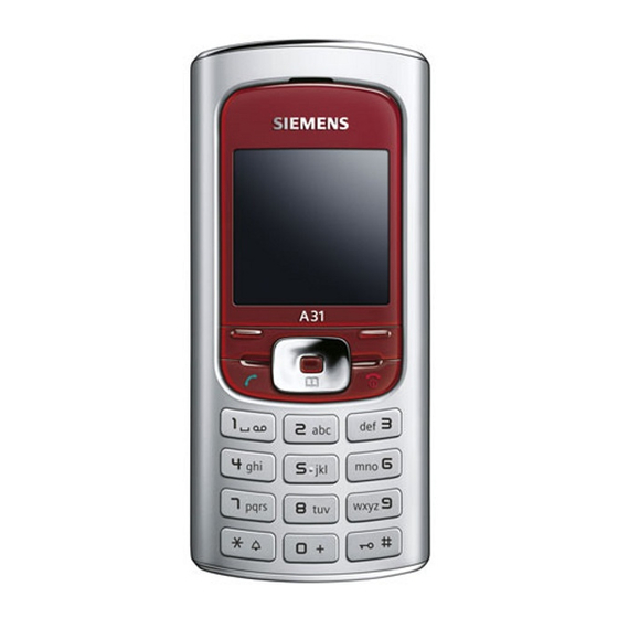
Release 1.0 3 Unit Description of A31 The A31 Finch is designed as a Mono Block with non-exchangeable housing. The Upper case and battery cover are painted parts (1k; 2 colours). IMD Lens will be mounted by double adhesive, display, 128X128(reuse from Pegasus); semi-bridge keypad, 4-way Navi-Key, 12 keys block; IMD lens (1pcs only);... -
Page 6: Exploded View Of A31
Release 1.0 4 Exploded View of A31 10/2005 Technical Documentation TD_Repair_L2.5L_A31_R1.0.pdf Page 6 of 46 Company Confidential 2005©BenQ... -
Page 7: Disassembly Of A31
Release 1.0 Disassembly of A31 All repairs as well as disassembling and assembling have to be carried out in an ESD protected environment and with ESD protected equipment/tools. For all activities the international ESD regulations have to be considered. For more details please check information in c – market https://market.benqmobile.com/SO/welcome.lookup.asp... - Page 8 Step 3 Remove Vibramotor by using Tweezers. Step 4 Remove Loudspeaker by using Tweezers. Step 5 Remove MMI from Upper Case Assy by using the Alternative Opening Tool carefully. 10/2005 Technical Documentation TD_Repair_L2.5L_A31_R1.0.pdf Page 8 of 46 Company Confidential 2005©BenQ...
- Page 9 Release 1.0 Step 6 To avoid scratches it is mandatory to place a protection foil onto the Display!!! Step 7 Remove Display by using the alternative opening tool carefully. 10/2005 Technical Documentation TD_Repair_L2.5L_A31_R1.0.pdf Page 9 of 46 Company Confidential 2005©BenQ...
- Page 10 Release 1.0 Step 8 Remove Earphone. Press the hocks together and lift the earphone up. Step 9 Remove keypad by using tweezers. 10/2005 Technical Documentation TD_Repair_L2.5L_A31_R1.0.pdf Page 10 of 46 Company Confidential 2005©BenQ...
-
Page 11: Assembly Of A31
Display Screws Upper Base Assy Lower Case Battery Assy Battery Cover Assy Keypad Assembly of A31 Step 1 Assemble Keypad by using Tweezers. Step 2 Assemble Earphone by using Tweezers. 10/2005 Technical Documentation TD_Repair_L2.5L_A31_R1.0.pdf Page 11 of 46 Company Confidential... - Page 12 Release 1.0 Step 3 Assemble Display module. Step 4 Remove the display protection foil. Step 5 Assemble Receiver by using tweezers. 10/2005 Technical Documentation TD_Repair_L2.5L_A31_R1.0.pdf Page 12 of 46 Company Confidential 2005©BenQ...
- Page 13 Release 1.0 Step 9 Assemble the Vibramotor by using tweezers. Step 10 Assemble MMI and Upper Case Assy. Step 11 Assemble Lower Case Assy. 10/2005 Technical Documentation TD_Repair_L2.5L_A31_R1.0.pdf Page 13 of 46 Company Confidential 2005©BenQ...
- Page 14 Release 1.0 Step 9 Assemble Battery and Battery Cover Assy. 10/2005 Technical Documentation TD_Repair_L2.5L_A31_R1.0.pdf Page 14 of 46 Company Confidential 2005©BenQ...
-
Page 15: Benq Mobile Service Equipment User Manual
BenQ Mobile Service Equipment User Manual Introduction Every LSO repairing BenQ Mobile handset must ensure that the quality standards are observed. BenQ Mobile has developed an automatic testing system that will perform all necessary measurements. This testing system is known as: BenQ Mobile Service Equipment •... -
Page 16: Grt Software: Functionality Configuration
Enter the value for “JPICS Server Timeout”. Be careful, this value defines how long GRT tries to reach the server until you get an error message. Do not select a very long time 10/2005 Technical Documentation TD_Repair_L2.5L_A31_R1.0.pdf Page 16 of 46 Company Confidential 2005©BenQ... - Page 17 GRT Software has now finished all required settings and configuration tasks. All files have been down- and uploaded. In dependency of the selected number of mobile phones and variants the volume of transferred date could be (~100MB) 10/2005 Technical Documentation TD_Repair_L2.5L_A31_R1.0.pdf Page 17 of 46 Company Confidential 2005©BenQ...
-
Page 18: Grt Software: Regular Usage
Personal Repair Personal Repair is always accessible. Basis for the decision if a SW-Update is authorised by BenQ Mobile is the so called Service Release-Table . Example: Mobile Phone has already SW50. Service -Release-Table shows SW50 In this case SW-Update is not necessary and therefore not authorised In any case customer data can be erased on request. - Page 19 Is the correct COM-Port selected o If a variant is missing, move back to Settings select the missing variant and conncet the GRM Server. Then continue with SW-Update. 10/2005 Technical Documentation TD_Repair_L2.5L_A31_R1.0.pdf Page 19 of 46 Company Confidential 2005©BenQ...
- Page 20 >>Appears in the window above. Remarks: The decision about a BenQ Mobile authorised SW-Update depends only on the Service Release-Table . The SW which is booted by GRT can be below the SW mentioned in the Service Release Table, if this SW is not released for the Net-Operator If xfs and mapping are activated, GRT will erase in any case the customer data even if the action is cancelled.
- Page 21 >>Appears in the window above. Remarks: The decision about a BenQ Mobile authorised SW-Update depends only on the Master-Table . The user has no chance to influence the decision Xfs and mapping are always activated there is no chance to deactivate them.
- Page 22 >>Appears in the window above. Remarks: The decision about a BenQ Mobile authorised SW-Update depends only on the Master-Table . The user has no chance to influence the decision Xfs and mapping can be activated on demand. GRT will erase in any case the customer data even if the action is cancelled.
-
Page 23: Jpics (Java Based Product Information Controlling System)
The following functions are available for the LSO: • General mobile information • Generate PINCODE • Generate SIMLOCK – UNLOCK – Code • Print IMEI labels • Lock, Unlock and Test the BF - Bus 10/2005 Technical Documentation TD_Repair_L2.5L_A31_R1.0.pdf Page 23 of 46 Company Confidential 2005©BenQ... - Page 24 – server can only be provided by the JPICS – TRUST – Center of the responsible department in Kamp – Lintfort. In case of any questions or requests concerning smart cards or administration of the databases please ask your responsible BenQ Mobile Customer Care Manager. 10/2005 Technical Documentation TD_Repair_L2.5L_A31_R1.0.pdf...
- Page 25 Here is a step by step instruction to install all the required components: It is necessary to follow this order! 1. Smart Card Reader (Omnikey: Cardman 2020 USB or Cardman 3121 USB) 2. CardOS interface (BenQ Mobile Version 3.0 B) 3. Java Runtime Environment (Sun) 4. Java additional components Every user is responsible for a proper installation matching the license agreements.
- Page 26 • Simlock – Unlock – Codes Masterphone codes The Masterphone code is used to unlock blocked mobiles. Masterphone codes can only be supplied for mobiles which have been delivered in a regular manner. 10/2005 Technical Documentation TD_Repair_L2.5L_A31_R1.0.pdf Page 26 of 46 Company Confidential 2005©BenQ...
- Page 27 • The user must be given the authorization to obtain Simlock – Unlock – Codes for the variant of the operator to which the mobile was delivered last time. 10/2005 Technical Documentation TD_Repair_L2.5L_A31_R1.0.pdf Page 27 of 46 Company Confidential 2005©BenQ...
- Page 28 This printer has to be connected to local LPT1 printer port (also see Installation of IMPRINT) and MUST feature a printing resolution of 300dpi. 10/2005 Technical Documentation TD_Repair_L2.5L_A31_R1.0.pdf Page 28 of 46 Company Confidential 2005©BenQ...
-
Page 29: International Mobile Equipment Identity, Imei
2 digits. 6 digits have been allocated for the equipment serial number for manufacturer and the last digit is spare. The part number for the A31 is S30880-S2920-#xxx where the last for letters specify the housing and software variant. -
Page 30: General Testing Information
The technical instruction for testing GSM mobile phones is to ensure the best repair quality. Validity This procedure is to apply for all from BenQ Mobile authorized level 1 up to 3 workshops. Procedure All following checks and measurements have to be carried out in an ESD protected environment and with ESD protected equipment/tools. - Page 31 If components and especially soldered components have to be replaced all rules mentioned in dedicated manuals or additional information e.g. service information have to be considered 10/2005 Technical Documentation TD_Repair_L2.5L_A31_R1.0.pdf Page 31 of 46 Company Confidential 2005©BenQ...
- Page 32 • highest PCL0 • Phase Error RMS • BS Power = -75 dBm • Phase Error Peak • middle BCCH • Average Power • Power Time Template Call release from BS 10/2005 Technical Documentation TD_Repair_L2.5L_A31_R1.0.pdf Page 32 of 46 Company Confidential 2005©BenQ...
- Page 33 Basis is the international standard of DIN ISO 2859. Use Normal Sample Plan Level II and the Quality Border 0, 4 for LSO. Remark: All sample checks must be documented. 10/2005 Technical Documentation TD_Repair_L2.5L_A31_R1.0.pdf Page 33 of 46 Company Confidential 2005©BenQ...
- Page 34 PUK 1 12345678 Pin 2 number: 0000 PUK 2 23456789 2) Test SIM Card from the company “T-D1” Pin 1 number: 1234 76543210 Pin 2 number: 5678 PUK 2 98765432 10/2005 Technical Documentation TD_Repair_L2.5L_A31_R1.0.pdf Page 34 of 46 Company Confidential 2005©BenQ...
- Page 35 Revision Letter (A, B,…) Sony Date code example P N A SO Year (O:2002, P:2003...) Supplier Code Month (1:Jan, 2:Feb,…9:Sep, O:Oct, N:Nov, D:Dec) (Maker’s marking) Revision Letter (A, B,…) 10/2005 Technical Documentation TD_Repair_L2.5L_A31_R1.0.pdf Page 35 of 46 Company Confidential 2005©BenQ...
-
Page 36: Introduction Of Service Repair Documentation For Level 3 Basic Repairs - A31
Level 3 Basic Repairs – A31 Purpose This part of Service Repair Documentation is intended to carry out repairs on BenQ Mobile repair level 3basic (only for workshops without level 3 equipment (special agreement required). The described failures shall be repaired in BenQ authorized local workshops only. -
Page 37: List Of Available Level 3 Basic Parts
(According to L2.5L-L2.5 General soldering information V1.3 - check C-market for updates) Jigs, Tools and working materials for all described repairs: hot air blower soldering gun tweezers flux solder 10/2005 Technical Documentation TD_Repair_L2.5L_A31_R1.0.pdf Page 37 of 46 Company Confidential 2005©BenQ... -
Page 38: A31 Board Layout
Release 1.0 16 A31 Board Layout Lower board side Connector SIM-Card IO Jack Nana 12-Pol Earphone Connector Connector Antenna Battery Upper board side Disdiode Led´s 10/2005 Technical Documentation TD_Repair_L2.5L_A31_R1.0.pdf Page 38 of 46 Company Confidential 2005©BenQ... -
Page 39: Sim Card Problems
Resolder new component afterwards. E-commerce order number: L50620-U6029-D670 E-commerce order name: FILTER EMI (Fi-Type6) PB Free Soldering temperature: ~ 360°C TIP Temp IRIS Diagnose Code: 43300 Interface/SIM Card reader/Mechanical Damage 10/2005 Technical Documentation TD_Repair_L2.5L_A31_R1.0.pdf Page 39 of 46 Company Confidential 2005©BenQ... -
Page 40: Io Connector Problems
E-commerce order number: L50634-Z93-C364 E-commerce order name: IO-JACK NANO 12-POL Soldering temperature: ~ 360°C TIP Temp. IRIS Diagnose Code: 46100 Interface/Charging Connector/Mechanical Damage 47300 Interface/Data Interface/Mechanical Damage 4B100 Interface/Headset Connector/Mechanical Damage 10/2005 Technical Documentation TD_Repair_L2.5L_A31_R1.0.pdf Page 40 of 46 Company Confidential 2005©BenQ... -
Page 41: Main Keypad Illumination Problems
Attention: Remove Metal Dome Sheet before!!! E-commerce order number: L36840-L2082-D670 E-commerce order name: LED BLUE TOP Soldering temperature: ~ 360°C TIP Temp. IRIS Diagnose Code: 36000 Keys / Illumination 10/2005 Technical Documentation TD_Repair_L2.5L_A31_R1.0.pdf Page 41 of 46 Company Confidential 2005©BenQ... -
Page 42: Connector Battery
Use hot air blower to remove defective component. Avoid excessive heat! Watch surrounding components! Resolder new component afterwards. E-commerce order number: L36334-Z97-C213 E-commerce order name: CONNECTOR BATTERY 3-POL Soldering temperature: 240 - 255°C IRIS Diagnose Code: 13000 Battery/Mechanical Damage 10/2005 Technical Documentation TD_Repair_L2.5L_A31_R1.0.pdf Page 42 of 46 Company Confidential 2005©BenQ... -
Page 43: Display Problems
Resolder new component afterwards. E-commerce order number: L36334-Z97-C205 E-commerce order name: CONNECTOR DISPLAY 10POL Soldering temperature: ~ 360°C TIP Temp. IRIS Diagnose Code: 21000 Display / Performance 22000 Display / Background Illumination 10/2005 Technical Documentation TD_Repair_L2.5L_A31_R1.0.pdf Page 43 of 46 Company Confidential 2005©BenQ... -
Page 44: Connector Rf Internal Antenna
81100 Radio / No Contact / Int. Antenna 81200 Radio / No Contact / Ext. Antenna 82100 Radio / Low Receiving Signal / Int. Antenna 82200 Radio / Low Receiving Signal / Ext. Antenna 10/2005 Technical Documentation TD_Repair_L2.5L_A31_R1.0.pdf Page 44 of 46 Company Confidential 2005©BenQ... - Page 45 83100 Radio / Dropped Calls / Int. Antenna 83200 Radio / Dropped Calls / Ext. Antenna 84100 Radios / Call Setup / Int. Antenna 84200 Radio / Call Setup / Ext. Antenna 10/2005 Technical Documentation TD_Repair_L2.5L_A31_R1.0.pdf Page 45 of 46 Company Confidential 2005©BenQ...
-
Page 46: Filter Emi Problems
Resolder new component afterwards. E-commerce order number: L50620-U6029-D670 E-commerce order name: FILTER EMI (Fi-Type6) PB Free Soldering temperature: ~ 360°C TIP Temp IRIS Diagnose Code: 47000 Data connectivity 11/2005 Technical Documentation TD_Repair_L1-L3_M580_R1.0.pdf Page 46 of 46 Company Confidential 2005©BenQ...
Need help?
Do you have a question about the A31 and is the answer not in the manual?
Questions and answers