
Related Manuals for Friedrich VERT-I-PAK B-SERIES


Summary of Contents for Friedrich VERT-I-PAK B-SERIES
- Page 1 INSTALLATION & OPERATION GUIDE ® VERT-I-PAK B-SERIES SINGLE PACKAGE VERTICAL AIR CONDITIONING SYSTEM 18,000 - 60,000 BTU/h 920-164-02 (10-04)
-
Page 2: Table Of Contents
920-164-02 (10-04) Table of Contents Safety Considerations ............................3 General Recommendations ........................... 3 Unpacking and Inspecting the Unit ........................3 Supplies Needed for Installation ..........................3 Accessories ................................4 General Specifi cations Model Number Identifi cation Guide ........................5 Dimensional Data V(E,H)B18,24,30,36 Unit Dimensions ........................ -
Page 3: Safety Considerations
920-164-02 (10-04) Safety Considerations Follow all safety codes. Wear safety glasses and work Improper installation, adjustment, alteration, service, gloves. Read these instructions thoroughly and follow all maintenance, or use can cause explosion, fi re, electrical warnings or cautions attached to the unit. Always install shock, or other conditions which may cause personal injury or units in accordance with local building codes, the National property damage. -
Page 4: Accessories
920-164-02 (10-04) Vert-I-Pak ® B Series ACCESSORIES MODEL DESCRIPTION PHOTO Telescoping wall plenums adjust to exact wall depth. Models with -8 suffi xes adjust 4 " - 8" deep; -14 models adjust 8" - 14". WALL PLENUM- Used when chassis is positioned against an exterior wall for outdoor air infi ltration. Recommended for use with 18,000 and 24,000 Btu/h units. -
Page 5: General Specifi Cations Model Number Identifi Cation Guide
920-164-02 (10-04) Section I – Nomenclature MODEL NUMBER 09 K 50 RT A EN GI NEER ING CODE SERIES V=Vertical Series OPTIONS E=Cooling with or without electric heat RT = Stan dard Re mote Op er a tion H=Heat Pump SP = Sea coast Pro tect ed DESIGN SERIES ELECTRIC HEATER SIZE... -
Page 6: E,H)B42,49 Unit Dimensions
920-164-02 (10-04) Figure 2 V(E,H)B42, 49 Unit Dimensions (Inches) 38.00 INDOOR AIR RETURN 19" x 27" NOM. OUTDOOR OUTDOOR OUTDOOR OUTDOOR INTAKE EXHAUST INTAKE EXHAUST 68.00 14.00 SERVICE PORT 21.00 22.5 22.5 ACCESS CONTROL BOX 23.25 ACCESS 5.50 16.25 11.6 11.6 INDOOR AIR SUPPLY... -
Page 7: Installation
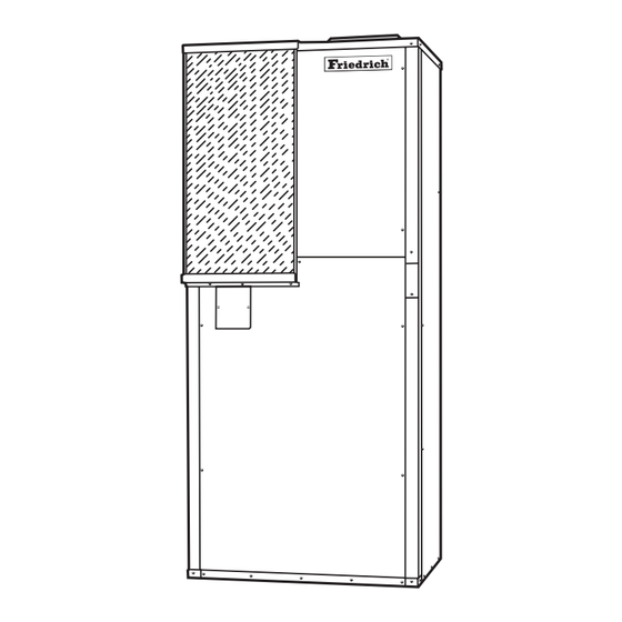
920-164-02 (10-04) Figure 4 Unit Confi guration Section III – Installation The Vert-I-Pak was designed for installation in residential from the outdoor air coil. The outdoor air intake and discharge and light commercial applications. These instructions detail openings are located on the back side of the unit. The unit may a typical method of installation. - Page 8 920-164-02 (10-04) Figure 5 VPBWP3 – 8/14 Wall Plenum For Models VE/VHB18 • VE/VHB24 • Figure 6 VPBWP4 – 8/14 Wall Plenum For Models VE/VHB18 • VE/VHB24 • VE/VHB30 • VE/VHB36 •...
- Page 9 920-164-02 (10-04) Figure 7 VPBWP5 – 8/14 Wall Plenum For Models VE/VHB42 • VE/VHB49 • Figure 8 VPBWP6 – 8/14 Wall Plenum For Model VE/VHB60 •...
-
Page 10: Indoor Air (Conditioned Supply Air) System
920-164-02 (10-04) Outdoor Fan Performance Table 1 Outdoor Blower Air Flow, SCFM 0.0" 0.1" 0.2" 0.3" VEB18 / VHB18 Outdoor 1160 1080 VEB24 / VHB24 Outdoor 1160 1080 VEB30 / VHB30 Outdoor 1300 1227 1131 1026 VEB36 / VHB36 Outdoor 1600 1550 1480... -
Page 11: Indoor Fan Performance
920-164-02 (10-04) C. Indoor-Air (Conditioned Supply Air) System The VEB/VHB series unit may be applied in either a free return If the unit is installed in a closet behind a door and the return air louver or grille is directly opposite the unit RA opening, air confi... -
Page 12: Electrical
920-164-02 (10-04) 2) Electrical The circuit breakers or fuses used for branch circuit protection DANGER: Electrical shock hazard. Turn OFF electric should be UL recognized. If circuit breakers are used, the power at the fuse box or service panel before making any circuit breaker for the compressor circuit must have a UL electrical connections and ensure a proper ground connection HACR rating. -
Page 13: Thermostat Mounting And Wiring
920-164-02 (10-04) Table 5 Heat Pumps Multiple Circuits Single Circuit HACR / Groung HACR / Groung Wire Size* Factory Breaker Wire Size* Wire Size* Max Breaker Size Wire Size (fi eld)* (fi eld) Size (fi eld) (fi eld) Circuit Voltage Breakers Voltage / Hz / Ph Range Ckt 1... -
Page 14: Wire Thermostat Cable To Unit Terminal
920-164-02 (10-04) 100 ft. from the unit (as measured along the control voltage drain line. This is to eliminate air trapping and allow proper wires), use No. 18 AWG color-coded wires to avoid excessive condensate drainage. voltage drop. Heat pumps generate condensate during both cooling and heating modes. -
Page 15: Identifying Your System
920-164-02 (10-04) Set system control to EM HEAT (Emergency Heat). NOTE: During EM HEAT operation, temperature of air fl owing Compressor should turn off and warm air should from room registers may be slightly warmer than during normal continue to fl ow from the registers. (This step is for HEAT mode operation. -
Page 16: Thermostat Operation
920-164-02 (10-04) particularly cool and humid weather. When this occurs, your Condensate heat pump senses this condition and goes through a defrost The heat pump may generate condensate during both the cycle. During the defrost cycle, the outdoor-air blower is turned cooling and heating modes of operation. -
Page 17: Heating Cycle
920-164-02 (10-04) reduce the amount of heat absorbed from outside air. To Heating Cycle maintain energy-effi cient operation, your heat pump has an With the SYSTEM control of your indoor thermostat set to automatic defrost cycle. HEAT, the heating section of your home comfort system will operate until room temperature is raised to the level you have The defrost cycle will occur only if ice is suffi... - Page 18 920-164-02 (10-04)
- Page 19 920-164-02 (10-04)
- Page 20 Use Factory Certifi ed Parts. FRIEDRICH AIR CONDITIONING CO. INC. Post Office Box 1540 · San Antonio, Texas 78295-1540 4200 N. Pan Am Expressway · San Antonio, Texas 78218-5212 (210) 357-4400 · FAX (210) 357-4480 www.friedrich.com Printed in the U.S.A.
Need help?
Do you have a question about the VERT-I-PAK B-SERIES and is the answer not in the manual?
Questions and answers