Subscribe to Our Youtube Channel
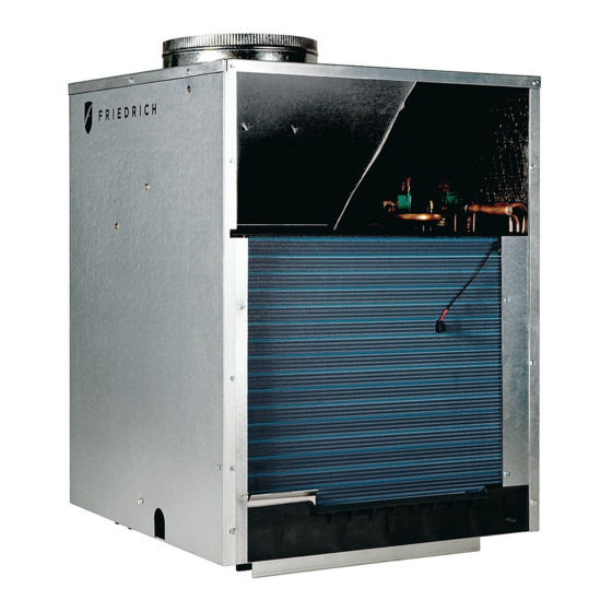
Summary of Contents for Friedrich VEA09K25
- Page 1 INSTALLATION & OPERATION GUIDE VERT-I-PAK ® A-SERIES SINGLE PACKAGE VERTICAL AIR CONDITIONING SYSTEM 9,000 - 18,000 BTU/h 920-075-09 (11-07)
-
Page 2: Table Of Contents
920-075-09 Table of Contents Installation Recommendations ..............................3 General Specifications Model Number Identification Guide ..............................4 VERT-I-PAK Chassis Specifications ............................... 4 Electrical Data ....................................4-5 Installation Utility Closet Dimensions ................................. 6 Wall Plenum & Architectural Louver Installation ..........................7 Drain Pan Installation ..................................8 Condensate Disposal Sysatem ............................... -
Page 3: Installation Recommendations
The above suggestions are for reference only and do not represent all possible installations. Please contact the factory for information regarding affects of other installation arrangements. By following these simple recommendations you can be confident that your Friedrich Vert-I-Pak will provide years of worry-free ®... -
Page 4: General Specifications
920-075-09 General Specifications Vert-I-Pak Model Identification Guide ® MODEL NUMBER 09 K 34 RT H ENGINEERING CODE SERIES V=Vertical Series OPTIONS RT = Standard Remote Operation E =Cooling with electric heat H =Heat Pump ELECTRIC HEATER SIZE DESIGN SERIES A Series A = 32"/47"... -
Page 5: Electrical Rating Tables
60°C WARNING LISTED Sample Nameplate MODEL NO 1 SERIAL NO * 120524 FRIEDRICH AIR CONDITIONING CO. SAN ANTONIO, TEXAS HEATING AND VOLTS: 24,33,34 COOLING EQUIPMENT ELECTRICAL SHOCK AND VOLTAGE RANGE: 255-197 REFRIG CHARGE: 7 OZS. R22... -
Page 6: Installation Utility Closet Dimensions
920-075-09 Installation Utility Closet Dimensions Recommended utility closet dimensions and a typical indoor installation are illustrated in Figure 1. Three inches minimum clearance on three sides of the unit must be allowed for return airflow, installation access and service access. See Figures 1 & 2 for clearances and reference dimensions. -
Page 7: Wall Plenum & Architectural Louver Installation
A. Install the wall plenum (VPAWP1-8/1-14) components in accordance with the installation instructions provided with each accessory. IMPORTANT REMINDER: FRIEDRICH WALL PLENUM IS NOT DESIGNED TO CARRY STRUCTURAL LOADS. PROPER WALL HEADER CONSTRUCTION IS REQUIRED. THE PLENUM REQUIRES PROPER FLASHING, SHIM AND CAULK FOR A WEATHER RESISTANT INSTALLATION. -
Page 8: Drain Pan Installation
Notes: and out of the ¾" internal drain connections. These are the Friedrich recommended return air grille/ filter/access panel arrangements. Consult the factory on Part 3: If Parts 1 & 2 fail for any reason, excess condensate other arrangements. -
Page 9: Chassis Installation
920-075-09 Ductwork Preparation Determining the Indoor CFM: Chart A – CFM Duct ESP: ESP (") Capacity To determine your system's indoor external static pressure (ESP, BTU/h 18000 12000 / 9000 in inches of water) use a duct calculator (as provided by your duct supplier). -
Page 10: Remote Thermostat
920-075-09 Remote Thermostat and Low Voltage Control Connections Remote Thermostat Thermostat Connections All Friedrich Vert-I-Pak units units are factory configured to be = Common Ground controlled by using a single stage remote wall mounted thermostat. W = Call for Heating The thermostat may be auto or manual changeover as long as the control configuration matches that of the Vert-I-Pak unit. -
Page 11: Electrical And Thermostat Wiring Diagrams
920-075-09 Figure 8 Electrical & Thermostat Wiring Diagrams CONNECTION TERMINAL NOTE: THE DIAGRAM ABOVE ILLUSTRATES THE TYPICAL THERMOSTAT WIRING. SEE THE UNIT CONTROL PANEL FOR THE ACTUAL UNIT WIRING DIAGRAM AND SCHEMATIC. -
Page 12: Chassis Operation
920-075-09 Chassis Final Connections Final Installation Checklist With the chassis in place, you are now ready to begin chassis Correct line voltage? connections: Chassis deck level? A. Move the thermostat switches to "OFF" and "AUTO." This Plenum divider baffle installed? will keep the thermostat from cycling the chassis until final ... -
Page 13: Servicing/Chassis Quick Changeouts
920-075-09 Service & Warranty To Remove the Chassis from the Closet: A. Switch the wall Thermostat off. Servicing / Chassis Quick Changeouts B. Pull the Power Disconnect located in the front of the chassis. C. Disconnect the thermostat wiring harness. The chassis is designed for quick disconnect and change out. -
Page 14: Error Codes
920-075-09 Error Codes The chart below lists the possible error codes and their description: Error Code Translation Action Taken by Unit Possible Cause Code An extreme low voltage condition Shut down unit. Display Error code and • Inadequate power supply exists <198V for 230V units and flash. -
Page 15: Accessories
VPSC2 match the exterior wall. DIGITAL THERMOSTAT Single stage, wall-mounted digital thermostat for control of Friedrich VERT-I-PAK. ACCESS PANEL / RETURN AIR GRILLE – Serves as an access panel to chassis and interior return air grille. A field-supplied (25" x 20") filter is mounted inside the hinged access door. -
Page 16: Warranty
Friedrich Air Conditioning Company - International Division. Any defective part to be replaced must be made available to FRIEDRICH in exchange for the replacement part. Reasonable proof must be presented to establish the date of install, otherwise the beginning date of this certificate will be considered to be our shipment date plus sixty days.


Need help?
Do you have a question about the VEA09K25 and is the answer not in the manual?
Questions and answers