Table of Contents
Advertisement
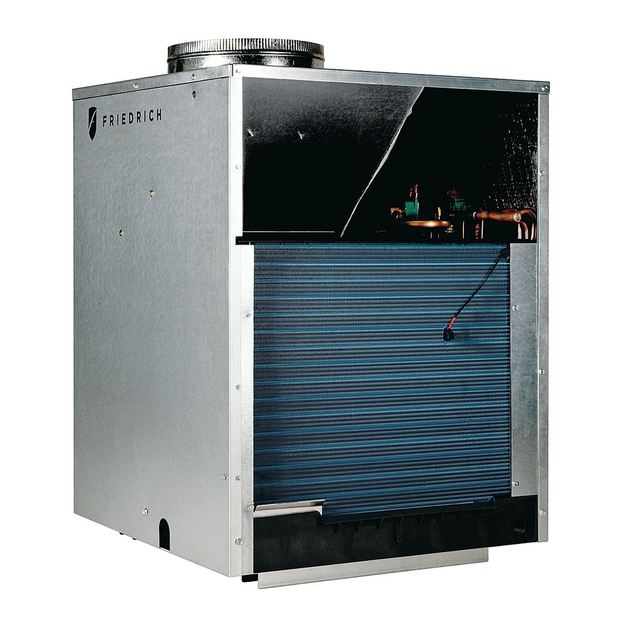
Service Manual
Single Package
Vertical Air Conditioning System
A – H Suffi x Models
MODELS
V(E,H)A09K25***
V(E,H)A12K25***
V(E,H)A18K25***
V(E,H)A24K25***
V(E,H)A24K75***
VPSERVMN (4-05)
A SERIES
V(E,H)A09K34***
V(E,H)A12K34***
V(E,H)A18K34***
V(E,H)A24K34***
V(E,H)A24K10***
V(E,H)A09K50***
V(E,H)A12K50***
V(E,H)A18K25***
V(E,H)A24K50***
V(E,H)A24K00***
*** Digits vary with model.
Advertisement
Table of Contents
Troubleshooting

Related Manuals for Friedrich H)A09K25


Summary of Contents for Friedrich H)A09K25
-
Page 1: Service Manual
Service Manual Single Package Vertical Air Conditioning System A – H Suffi x Models MODELS V(E,H)A09K25*** V(E,H)A12K25*** V(E,H)A18K25*** V(E,H)A24K25*** V(E,H)A24K75*** VPSERVMN (4-05) A SERIES V(E,H)A09K34*** V(E,H)A12K34*** V(E,H)A18K34*** V(E,H)A24K34*** V(E,H)A24K10*** V(E,H)A09K50*** V(E,H)A12K50*** V(E,H)A18K25*** V(E,H)A24K50*** V(E,H)A24K00*** *** Digits vary with model. -
Page 2: Table Of Contents
Introduction ...3 Vert-I-Pak Model Number Identifi cation Guide ...4 Serial Number Identifi cation Guide ...4 H Suffi x Chassis Specifi cations ...5 E and G Suffi x Chassis Specifi cations ...6 A and D Suffi x Chassis Specifi cations ...7 Sequence Of Operation ...8 Electrical Supply ...9 Supply Circuit ...9... -
Page 3: Introduction
If you install or perform service on equipment, you must assume responsibility for any bodily injury or property damage which may result to you or others. Friedrich Air Conditioning Company will not be responsible for any injury or property damage arising from improper installation, service, and/or service procedures. -
Page 4: Vert-I-Pak Model Number Identifi Cation Guide
MODEL NUMBER SERIES V=Vertical Series E=Cooling with or without electric heat H=Heat Pump DESIGN SERIES A = 32" and 47" Cabinet NOMINAL CAPACITY A-Series (Btu/h) 09 = 9,000 12 = 12,000 18 = 18,000 24 = 24,000 VOLTAGE K = 208/230V-1Ph-60Hz SERIAL NUMBER Decade Manufactured J = 9... -
Page 5: Electric Heat Data
VERT-I-PAK ® H SUFFIX CHASSIS SPECIFICATIONS VEA/VHA9K-24K VEA09K C O O L I N G D A T A Cooling Btu/h 9500/9300 Cooling Power (W) 10.8 Sensible Heat Ratio 0.74 H E A T P U M P D A T A Heating Btu/h COP @ 47°F Heating Power (W) -
Page 6: E And G Suffi X Chassis Specifi Cations
VERT-I-PAK ® E & G SUFFIX CHASSIS SPECIFICATIONS Model Voltage (V) Refrigerant Chassis Width Chassis Depth Chassis Height ** Shipping W x D x H Supply Duct Collar *** Drain Connection Min. Circuit Amps CFM Indoor Max. Duct ESP ** Height includes 2" duct collar & isolators under unit. *** Factory collar accepts 10" fl ex duct. VEA / VHA9K-24K VEA09K C O O L I N G... -
Page 7: A And D Suffi X Chassis Specifi Cations
Fan Speeds Max. Duct ESP NOTES: ** Height includes 2" duct collar & isolators under unit. *** Factory collar accepts 10" fl ex duct. MODELS V(E,H)A09K25 V(E,H)A09K34 V(E,H)A09K50 V(E,H)A12K25 V(E,H)A12K34 V(E,H)A12K50 V(E,H)A18K25 V(E,H)A18K34 V(E,H)A18K50 Cooling Cap. (Btu/h) 9500/9300 9500/9300 Cooling Power (W) SEER 10.0... -
Page 8: Sequence Of Operation
Sequence of Operation A good understanding of the basic operation of the refrigeration system is essential for the service technician. Without this understanding, accurate troubleshooting of refrigeration system problems will be more diffi cult and time consuming, if not (in some cases) entirely impossible. The refrigeration system uses four basic principles (laws) in its operation they are as follows: 1. -
Page 9: Electrical Supply
Electrical Supply WARNING: Electrical shock hazard. Turn OFF electric power at fuse box or service panel before making any electrical connections and ensure a proper ground connection is made before connecting line voltage. All electrical connections and wiring MUST be installed by a qualifi... -
Page 10: Room Thermostats
Room Thermostats Room thermostats are available from several different manufacturers in a wide variety of styles. They range from the very simple Bimetallic type to the complex electronic set-back type. In all cases, no matter how simple or complex, they are simply a switch (or series of switches) designed to turn equipment (or components) "ON"... -
Page 11: Electrical & Thermostat Wiring Diagrams
Typical Electrical & Thermostat Wiring Diagrams THERMOSTAT (FRONT) THERMOSTAT CONNECTIONS (EAR) BROWN BLACK BLUE COMP WIRE HARNESS COMPRESSOR TERM BOARD BLACK BLUE GREEN YELLOW WHITE NOTE: THE DIAGRAM ABOVE ILLUSTRATES THE TYPICAL THERMOSTAT WIRING AND 208 VOLT TRANSFORMER WIRING. SEE THE UNIT CONTROL PANEL FOR THE ACTUAL UNIT WIRING DIAGRAM AND SCHEMATIC. - Page 12 Typical Electrical & Thermostat Wiring Diagrams G & H Suffi x COM. 208V 240V THERMOSTAT (FRONT) NOTE: THE DIAGRAM ABOVE ILLUSTRATES THE TYPICAL THERMOSTAT WIRING AND 208 VOLT TRANSFORMER WIRING. SEE THE UNIT CONTROL PANEL FOR THE ACTUAL UNIT WIRING DIAGRAM AND SCHEMATIC.
- Page 13 Typical Electrical & Thermostat Wiring Diagrams A – E Suffi x FOR 208 VOLT MODELS ONLY: MOVE THE WHITE WIRE AS SHOWN BELOW.
-
Page 14: Indoor Blower - Air Flow
Indoor Blower - Airfl ow The current Vert-I-Pak 9, 12, & 18 use a dual shaft, permanent split capacitor, single speed motor to drive indoor blower and outdoor fan. Earlier model VERT-I-Pak units used 2-speed motors. The Vert-I-Pak 24 uses an individual, single shaft, permanent split capacitor, single speed motor for the indoor blower, and a separate motor drives the outdoor fan. -
Page 15: Checking External Static Pressure
Checking External Static Pressure The airflow through the unit can be determined by measuring the external static pressure of the system, and consulting the blower performance data for the specifi c VERT-I-PAK. 1. Set up to measure external static pressure at the supply and return air. -
Page 16: Airfl Ow Charts
Airfl ow Charts A – D Suffi x Chart A CFM @ 230 Volts - DRY COIL Model — > V(E,H)A09/A12 Fan Speed — > High ESP (in water) 0.00 0.10 0.20 0.30 Ductwork Preparation Pull the fl ex duct tight. Extra fl ex duct slack can greatly increase static pressure Explanation of charts Chart A is the nominal dry coil VERT-I-PAK CFMs. -
Page 17: Method Of Charging
Method Of Charging The acceptable method for charging the Vert-I-Pak system is the Weighed in Charge Method. The weighed in charge method is applicable to all units. It is the preferred method to use, as it is the most accurate. The weighed in method should always be used whenever a charge is removed from a unit such as for a leak repair, compressor replacement, or when there is no refrigerant... -
Page 18: Overcharged Refrigerant Systems
Overcharged Refrigerant Systems Compressor amps will be near normal or higher. Noncondensables can also cause these symptoms. To confi rm, remove some of the charge, if conditions improve, system may be overcharged. If conditions don’t improve, Noncondensables are indicated. Whenever an overcharged system is indi cated, always make sure that the problem is not caused by air fl... -
Page 19: Capillary Tube Systems
Metering Device - Capillary Tube Systems All units are equipped with capillary tube metering devices. Checking for restricted capillary tubes. Connect pressure gauges to unit. Start the unit in the cooling mode. If after a few minutes of operation the pressures are normal, the check valve and the cooling capillary are not restricted. -
Page 20: Checking Reversing Valves
Checking Reversing Valve NOTE: You must have normal operating pressures before the reversing valve can shift. Check for proper refrigerant charge. Sluggish or sticky reversing valves can sometimes be remedied by reversing the valve several time with the airfl ow restricted to increase system pressure. -
Page 21: Compressor Checks
WARNING DANGER OF BODILY INJURY OR DEATH FROM ELECTRICAL SHOCK When working on high voltage equipment - turn the electrical power off before attaching test leads. Use test leads with alligator type clips - clip to terminals, turn power on, take reading - turn power off before removing leads. -
Page 22: Compressor Single Phase Resistance Test
Single Phase Resistance Test Remove the leads from the compressor terminals and set the ohmmeter on the lowest scale (R x 1). Touch the leads of the ohmmeter from terminals common to start ("C" to "S"). Next, touch the leads of the ohmmeter from terminals common to run ("C"... -
Page 23: Capacitors
WARNING HAZARD OF SHOCK AND ELECTROCUTION. A CAPACITOR CAN HOLD A CHARGE FOR LONG PERIODS OF TIME. A SERVICE TECHNICIAN WHO TOUCHES THESE TERMINALS CAN BE INJURED. NEVER DISCHARGE THE CAPACITOR BY SHORTING ACROSS THE TERMINALS WITH A SCREWDRIVER. Capacitors Many motor capacitors are internally fused. -
Page 24: Emergency Heat Switch
Emergency Heat Switch (Defrost Thermostat) Continuity Check Electric Heat Switch Operation (Heat Pumps Only) The electric heat switch is a dual function control and is shown on the wiring diagram as a defrost thermostat. It may be adjusted using a screwdriver. As the control shaft is rotated counter clockwise a detent will be encountered. -
Page 25: Wiring Diagram Index
MODEL DIAGRAM VEA09K00 RTA ... 80004910 ...28 VEA09K00RTB ... 80004910 ...28 VEA09K00RTE ... 80004910 ...28 VEA09K00RTG ... 80004922 ...34 VEA09K00RTH ... 80004922 ...34 VEA09K25 RTA ... 80004911 ...30 VEA09K25RTB ... 80004911 ...30 VEA09K25RTE ... 80004911 ...30 VEA09K25RTG ... 80004923 ...35 VEA09K25RTH ... - Page 26 MODEL DIAGRAM VEA18K50RTG ... 80004920 ...32 VEA18K50RTH ... 80004920 ...32 VEA24K00RTH ... 80110500 ...37 VEA24K10RTH ... 80108800 ...38 VEA24K25RTH ... 80108800 ...38 VEA24K34RTH ... 80108800 ...38 VEA24K50RTH ... 80108800 ...38 VEA24K75RTH ... 80108800 ...38 VHA09K25RTA ... 800004912 ...29 VHA09K25RTB ... 800004912 ...29 VHA09K25RTE ...
-
Page 39: 9-18 Electrical Troubleshooting Chart - Cooling
9-18 ELECTRICAL TROUBLESHOOTING CHART — COOLING Compressor runs but Fan runs but Fan doesn't Compressor doesn't Turn Fan Switch of Room Thermostat to "On" position or jump "R" to "G" at Terminal board O.K. Does Fan Motor operate now? 24Volts at Coil Terminals of Blower Problem indicated in Control wiring and/or... -
Page 40: 2-Ton Electrical Troubleshooting Chart - Cooling
2-TON ELECTRICAL TROUBLESHOOTING CHART — Cooling Compressor and outdoor Indoor blower runs but fan motor run but indoor outdoor fan motor and blower does not run compressor do not run Turn Fan Switch of Room Thermostat to "On" position or jump "R" to "G"... -
Page 41: Troubleshooting Chart - Cooling
TROUBLESHOOTING CHART — COOLING REFRIGERANT SYSTEM DIAGNOSIS COOLING Low Suction Pressure High Suction Pressure Low Load Conditions High Load Conditions Low Air Flow Across High Air Flow Across Indoor Coil Refrigerant System Reversing Valve not Restriction Undercharged Moisture in System Defective Compressor TROUBLESHOOTING CHART —... -
Page 42: Electrical Troubleshooting Chart Heat Pump
ELECTRICAL TROUBLESHOOTING CHART Is Line Voltage Present at Solenoid Valve? Is the Solenoid Coil Good? Reversing Valve Stuck Replace Reversing Valve HEAT PUMP HEAT PUMP SYSTEM COOLS WHEN HEATING IS DESIRED. Replace Solenoid Coil Is Selector Switch set for Heat? - Page 44 Use Factory Certifi ed Parts. FRIEDRICH AIR CONDITIONING CO. Post Office Box 1540 · San Antonio, Texas 78295-1540 4200 N. Pan Am Expressway · San Antonio, Texas 78218-5212 (210) 357-4400 · FAX (210) 357-4480 www.friedrich.com Printed in the U.S.A. VPSERVMN (4-05)
Need help?
Do you have a question about the H)A09K25 and is the answer not in the manual?
Questions and answers