Table of Contents

Related Manuals for Toa SR-T5


Summary of Contents for Toa SR-T5
- Page 1 OPERATING INSTRUCTIONS LINE ARRAY SPEAKER SR-T5 WALL PAN BRACKET (optional) SR-PB5 Thank you for purchasing TOA's Line Array Speaker. Please carefully follow the instructions in this manual to ensure long, trouble-free use of your equipment.
-
Page 2: Table Of Contents
8. BEFORE INSTALLING THE SPEAKER 8.1. Anchor Bolt Mounting Dimensions ..............12 8.2. Speaker Cable Outlet Position When Installing the SR-T5 Flat against Wall .. 12 9. MOUNTING TO THE WALL 9.1. When Installing the SR-T5 Using the Supplied Mounting Bracket Only (Downward angle adjustable) 9.1.1. -
Page 3: Safety Precautions
1. SAFETY PRECAUTIONS • Before installation or use, be sure to carefully read all the instructions in this section for correct and safe operation. • Be sure to follow all the precautionary instructions in this section, which contain important warnings and/or cautions regarding safety. - Page 4 Indicates a potentially hazardous situation which, if mishandled, could CAUTION result in moderate or minor personal injury, and/or property damage. When Installing the Unit • When unpacking or moving the unit, be sure to handle it with two or more persons. Falling or dropping the unit may cause personal injury and/or property damage.
-
Page 5: General Description
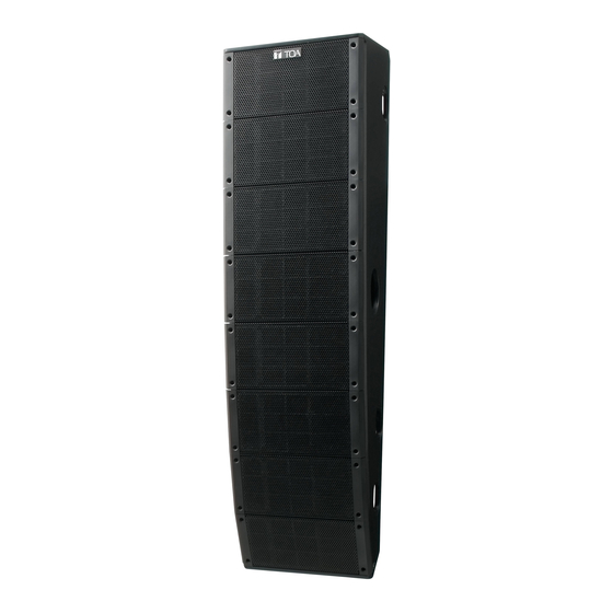
2. GENERAL DESCRIPTION The TOA SR-T5 is a 2-way line array speaker in which low- and high-frequency speaker units are arranged vertically within close proximity to each another. Its excellent speech clarity and sturdy impact-resistant construction make it ideal for installation in sports facilities with strong reverberation, such as school gymnasiums. -
Page 6: Nomenclature And Dimensional Diagrams
4. NOMENCLATURE AND DIMENSIONAL DIAGRAMS 4.1. SR-T5 Line Array Speaker 4.1.1. Speaker [Top] M10 Nut (for suspension use) Unit: mm (inches) Used for temporarily suspending the speaker at installation. (Refer to p. 15 and p. 21.) Safety wire mounting bolts... -
Page 7: Sr-Pb5 Wall Pan Bracket (Optional)
4 - M8 For anchor bolt (Refer to p. 12 and p. 19.) Use this hole to join the bracket supplied with the SR-T5. (Refer to p. 18.) Unit: mm (inches) Unit: mm (inches) Horizontal angle adjustment hole (for 5°) Horizontal angle adjustment hole (for 10°) -
Page 8: Input Terminal Connection
6. INPUT TERMINAL CONNECTION Speaker Cable entry hole (on the rear) Pull the cable to take up Input terminal the slack after connection (on the side) completion. Input terminal Cable Speaker Speaker entry hole cable cable Step 1. Run the speaker cable through the cable entry hole in the speaker's rear panel, then lead it out from the side panel. -
Page 9: Changing To High Impedance
7. CHANGING TO HIGH IMPEDANCE The speaker can be used for high-impedance application with the installation of the optional MT-S0601 Matching Transformer. To install the MT-S0601 transformer, remove the blank panel on the speaker's rear panel. Step 1. Remove 4 screws holding the blank panel and detach the panel. Note When removing the blank panel, do not forcibly pull it since the interlocked connectors used to connect the matching transformer is tied to the blank panel's back side. - Page 10 Step 3. Connect a lead wire to the desired impedance tap. Never connect to an 83 Ω tap when using the speaker on CAUTION high impedance 100 V line. Otherwise, heat builds up in the matching transformer, possibly causing a fire. Note Make wiring to the tap before installing the transformer Connector...
- Page 11 Step 5. Replace the blank panel with the matching transformer fixed in the speaker. Note When replacing the blank panel, take care not to pinch the lead wire. Speaker Blank panel Machine screw M4 x 25 Step 6. Attach the supplied impedance indication label to the given place in the speaker nameplate. Select the indication label corresponding to the impedance set in step 3 from 4 different labels.
-
Page 12: Before Installing The Speaker
8. BEFORE INSTALLING THE SPEAKER Anchor bolts must first be installed when mounting the SR-T5 line array speaker on a wall. 8.1. Anchor Bolt Mounting Dimensions M10 Safety Wire Anchor Bolt When using the supplied mounting bracket or the optional SR-PB5 Wall Pan... -
Page 13: Mounting To The Wall
9. MOUNTING TO THE WALL 9.1. When Installing the SR-T5 Using the Supplied Mounting Bracket Only (Downward angle adjustable) The speaker can be mounted flat or at a downward angle of 1º, 2º, or 3º against wall using the supplied mounting bracket. -
Page 14: Rough Installation Plan
9.1.2. Rough installation plan Safety wire (accessory) Anchor bolt (required separately) Speaker Mounting Bracket A (accessory) Wall surface Mounting Bracket B (accessory) 9.1.3. Installation procedure The example here shows the procedure to install the speaker on the left side wall as viewed toward the stage. Step 1. - Page 15 Step 2. Install the supplied mounting brackets on the wall. Secure the Mounting Bracket A to the upper anchor bolts and the Bracket B to the lower anchor bolts. M10 anchor bolt for the safety wire (required separately) Mounting Bracket A (accessory) M10 anchor bolt for the mounting bracket (required separately) Nuts and washers...
- Page 16 Step 4. Screw 2 supplied hex bolts loosely to the speaker. Follow the same installation procedure to the other side. Fix the hex bolt loosely leaving about 5 – 7 mm (0.2" – 0.28") protruding. Hex bolt M8 x 40 (accessory) About 5 –...
- Page 17 Step 8. Determine the speaker’s downward angle, then fix the speaker with the supplied hex bolts. 8-1. Fix the Mounting Bracket B (lower side of the speaker) loosely with the supplied hex bolts. Fix it loosely to the extent that the speaker can be inclined when adjusting the speaker angle. 8-2.
-
Page 18: When Installing The Speaker In Conjunction With The Optional Sr-Pb5
SR-PB5 Wall Pan Bracket. 9.2.1. Rough installation plan Safety wire (accessory) Anchor bolt (required separately) Mounting Bracket A Speaker (supplied with the SR-T5) Pan Bracket A (supplied with the SR-PB5) Pan Bracket B (supplied with the SR-PB5) Wall surface... - Page 19 Pan Bracket A (supplied with the SR-PB5) Nuts and washers (required separately) Step 3. Attach 2 SR-PB5’s Pan brackets B to the Mounting Brackets A and B supplied with the SR-T5. Note When installing the speaker on the right side wall as viewed toward the stage, position each Pan Bracket B upside down.
- Page 20 Step 4. Install the Pan Brackets B to the Pan Brackets A secured to the wall. In this case, set the speaker’s horizontal angle. Note: Be sure to set both upper and lower Pan Brackets B at equal angles. Horizontal angle adjustment The mounting position of this bolt determines the horizontal angle.
- Page 21 When using the supplied eye bolt at the speaker installation Eyebolt M10 x 30 Remove the hole plug on the speaker’s top, then (accessory) install the supplied eye bolt instead. Remove the hole plug. Note As this eyebolt is for temporarily suspending the speaker at installation, never use this eyebolt for permanent installation of the speaker.
- Page 22 Step 8. Install the safely wire to the wall. M10 safety wire anchor bolt Install the end of the safety wire attached to the speaker to the anchor bolt installed Nut and washers on the wall surface. (required separately) Safety wire Speaker Step 9.
- Page 23 Step 11. Attach the supplied side covers. Attach the supplied side covers to the upper side (Mounting Bracket A side), the lower side (Mounting Bracket B side), and the input terminal section. (5 points) Side cover (accessory) Machine screw M4 x 10 (accessory) Note The figure above shows an example for attaching the covers to the upper side (Mounting Bracket A side).
-
Page 24: Specifications
Weight 29 kg (63.93 lb) (including accessories) Optional Product Wall Pan Bracket: SR-PB5 (to be used with SR-T5's accessory bracket) Matching Transformer: MT-S0601 Note: The design and specifications are subject to change without notice for improvement. • Accessories Mounting Bracket A ........1 Hex bolt M10 x 40 (w/washer) ....
Need help?
Do you have a question about the SR-T5 and is the answer not in the manual?
Questions and answers