Table of Contents
Advertisement
Quick Links
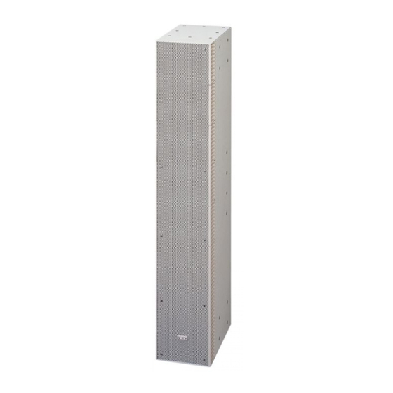
LINE ARRAY SPEAKERS
EXTENSION PLATE
PROTECTION PAD
Thank you for purchasing TOA's Line Array Speakers and their associated products.
Please carefully follow the instructions in this manual to ensure long, trouble-free use of your equipment.
(optional)
(optional)
SR-S4LWP
OPERATING INSTRUCTIONS
SR-S4LWP
SR-S4SWP
SR-EP4WP
SR-PP4
SR-S4SWP
Advertisement
Table of Contents


Need help?
Do you have a question about the SR-S4LWP and is the answer not in the manual?
Questions and answers