Yamaha RDX-E700 Service Manual
Micro component system
Hide thumbs
Also See for RDX-E700:
- Owner's manual (110 pages) ,
- Owner's manual (428 pages) ,
- Owner's manual (160 pages)
Table of Contents
Advertisement
MICRO COMPONENT SYSTEM
RDX-E700/
This manual has been provided for the use of authorized YAMAHA Retailers and their service personnel.
It has been assumed that basic service procedures inherent to the industry, and more specifically YAMAHA Products, are already
known and understood by the users, and have therefore not been restated.
WARNING:
IMPORTANT:
The data provided is believed to be accurate and applicable to the unit(s) indicated on the cover. The research, engineering, and service
departments of YAMAHA are continually striving to improve YAMAHA products. Modifications are, therefore, inevitable and
specifications are subject to change without notice or obligation to retrofit. Should any discrepancy appear to exist, please contact the
distributor's Service Division.
WARNING:
IMPORTANT:
CONTENTS
TO SERVICE PERSONNEL . . . . . . . . . . . . . . . . . . 2-4
PREVENTION OF ELECTRO STATIC DISCHARGE . . . . . . 4
LOCALE MANAGEMENT INFORMATION . . . . . . . . 5
FRONT PANEL . . . . . . . . . . . . . . . . . . . . . . . . . . . . . . 6
REMOTE CONTROL PANELS . . . . . . . . . . . . . . . . . . 6
REAR PANELS . . . . . . . . . . . . . . . . . . . . . . . . . . . . . . 7
SPECIFICATIONS /
DIMENSIONS /
. . . . . . . . . . . . . . . . . . . . . . . . . 9
. . . . . . . . . . . . . . . . . . . . . . . 10-11
© 2005 YAMAHA CORPORATION. All rights reseved.
1 0 0 9 9 1
This manual is copyrighted by YAMAHA and may not be copied or
redistributed either in print or electronically without permission.
The MCR-E700 consists of the RDX-E700 and the NX-E700.
IMPORTANT NOTICE
Failure to follow appropriate service and safety procedures when servicing this product may result in personal
injury, destruction of expensive components, and failure of the product to perform as specified. For these reasons,
we advise all YAMAHA product owners that any service required should be performed by an authorized YAMAHA
Retailer or the appointed service representative.
The presentation or sale of this manual to any individual or firm does not constitute authorization, certification or
recognition of any applicable technical capabilities, or establish a principle-agent relationship of any form.
Static discharges can destroy expensive components. Discharge any static electricity your body may have
accumulated by grounding yourself to the ground buss in the unit (heavy gauge black wires connect to this buss).
Turn the unit OFF during disassembly and part replacement. Recheck all work before you apply power to the unit.
. . . . . . . . . . . . . . . . . . 8-9
. . . . . . . . . . . . . . . . . . . . 10
MCR-E700
NX-E700
SERVICE MANUAL
SERVICE MANUAL
PRINTED CIRCUIT BOARD . . . . . . . . . . . . . . . . 13-16
BLOCK DIAGRAM . . . . . . . . . . . . . . . . . . . . . . . . . . . 17
SCHEMATIC DIAGRAM . . . . . . . . . . . . . . . . . . . 18-23
RDX-E700 EXPLODED VIEW . . . . . . . . . . . . . . . . . . 24
RDX-E700 MECHANICAL PARTS . . . . . . . . . . . 25-26
NX-E700 . . . . . . . . . . . . . . . . . . . . . . . . . . . . . . . . . . . 27
REMOTE CONTROL . . . . . . . . . . . . . . . . . . . . . . 28-29
12
12
'05.11
Advertisement
Table of Contents

Related Manuals for Yamaha RDX-E700


Summary of Contents for Yamaha RDX-E700
-
Page 1: Table Of Contents
REAR PANELS ......7 RDX-E700 EXPLODED VIEW ....24 RDX-E700 MECHANICAL PARTS . -
Page 2: To Service Personnel
RDX-E700/NX-E700 TO SERVICE PERSONNEL AC LEAKAGE 1. Critical Components Information EQUIPMENT WALL TESTER OR Components having special characteristics are marked Z OUTLET UNDER TEST EQUIVALENT and must be replaced with parts having specifications equal to those originally installed. 2. Leakage Current Measurement (For 120V Models Only) - Page 3 RDX-E700/NX-E700 2. If lead solder must be used, be sure to remove lead free solder from each terminal section of the parts to be replaced and from the area around it completely before soldering, or make sure that the lead free solder and lead solder melt together fully.
-
Page 4: Prevention Of Electro Static Discharge
RDX-E700/NX-E700 CAUTION Use of controls or adjustments or performance of procedures CLASS 1 LASER PRODUCT other than those specified herein may result in hazardous LASERE KLASSE 1 PRODUKT radiation exposure. CAUTION- VISIBLE AND INVISIBLE AVERTISSEMENT LASER RADIATION WHEN OPEN. DO NOT STARE INTO BEAM OR VIEW DIRECTLY L’utilisation de commandes et l’emploi de réglages ou de... -
Page 5: System Composition
M a c r o v i s i o n C o r p o r a t i o n . R e v e r s e engineering or disassembly is prohibited. SYSTEM COMPOSITION The MCR-E700 consists of the RDX-E700 and the NX-E700. NX-E700 NX-E700... -
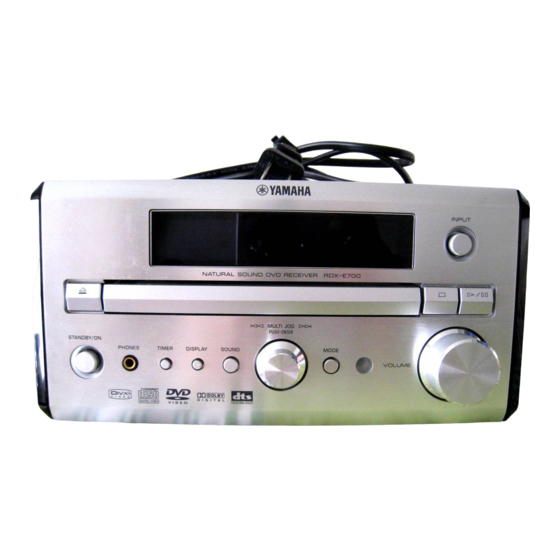
Page 6: Front Panel
RDX-E700/NX-E700 FRONT PANEL REMOTE CONTROL PANELS U, C, T, K, A, L, V, J models B, G models... -
Page 7: Rear Panels
RDX-E700/NX-E700 REAR PANELS U, C models B, G models T model L model K model V model A model J model... - Page 8 RDX-E700/NX-E700 SPECIFICATIONS RDX-E700 • WMA: Up to 192 kbps (not support 32 kbps), AMPLIFIER SECTION / 32 kHz, 44.1 kHz, 48 kHz sampling rate / • Minimum RMS output power per channel (20 kHz Factory LPF) / (6 ohoms, 1 kHz, 0.18% THD) ....20 W + 20 W •...
- Page 9 RDX-E700/NX-E700 NX-E700 • Type / ... . 2-Way Bass Reflex Speaker System Manufactured under license from Dolby Laboratories. “Dolby” and the double-D symbol are trademarks of Dolby Laboratories. Magnetic Shielding Type •...
-
Page 10: Internal View
MAIN (1) P.C.B. POWER SUPPLY UNIT FRONT P.C.B. DVD MECHANISM ASS’Y RDX-E700 DISASSEMBLY PROCEDURES • Remove parts in disassembly order as numbered. • Disconnect the power cable from the AC outlet. 1. Removal of Top Cover a. Remove 2 screws ( ) and 4 screws ( ). - Page 11 RDX-E700/NX-E700 Fig. 2 Fig. 1 HOW TO MANUALLY EJECT THE TRAY a. Turn the unit bottom up. b. Turn the Loading Gear in the direction indicated with a screwdriver until the tray is ejected. c. Gently pull the tray out.
-
Page 12: Tray Lock Mode
RDX-E700/NX-E700 TRAY LOCK MODE In the TRAY LOCK mode, the tray open/close function is stopped temporarily. Setting Tray Lock mode 1. With the power turned off, while pressing the "TIMER" key and "MODE" key, keep pressing the "STANDBY/ON" key for 4 seconds or longer. -
Page 13: Printed Circuit Board
RDX-E700/NX-E700 PRINTED CIRCUIT BOARD FOR INFORMATION ONLY (NO REPLACEMENT COMPONENT PARTS WILL BE AVAILABLE) MPEG P.C.B. MPEG P.C.B. DVD MECHANISM DVD MECHANISM (Side A) Lead Free Solder Used (Side B) Lead Free Solder Used (OPEN/CLOSE) (SPINDOLE & SLED) - Page 14 RDX-E700/NX-E700 VIDEO OUT PRINTED CIRCUIT BOARD SUBWOOFER SPEAKERS (B, G models) VIDEO FOR INFORMATION ONLY (NO REPLACEMENT COMPONENT PARTS WILL BE AVAILABLE) (B, G models) MAIN (1) P.C.B. MAIN (2) P.C.B. (Side A) Lead Free Solder Used (Side A) Lead Free Solder Used...
- Page 15 RDX-E700/NX-E700 PRINTED CIRCUIT BOARD FOR INFORMATION ONLY (NO REPLACEMENT COMPONENT PARTS WILL BE AVAILABLE) MAIN (1) P.C.B. (Side B) Lead Free Solder Used MAIN (2) P.C.B. (Side B) Lead Free Solder Used MAIN (3) P.C.B. (Side B) Lead Free Solder Used...
- Page 16 RDX-E700/NX-E700 PRINTED CIRCUIT BOARD Lead Free Solder Used FOR INFORMATION ONLY (NO REPLACEMENT COMPONENT PARTS WILL BE AVAILABLE) FRONT P.C.B. (Side A) MAIN (1) CN14 VOLUME DISPLAY SOUND TIMER MODE PHONES STANDBY/ON POWER SUPPLY UNIT (Side A) POWER CABLE MAIN (1)
-
Page 17: Block Diagram
RDX-E700/NX-E700 BLOCK DIAGRAM AMP PART HEAD PHONE IC62 DOWN MIXOUT H/P OUT FILTER NJM4556AL IC63 SUB PRE OUT BUFFER FILTER OPAMP IC81 M2068MD WM8776 SUB_PREOUT IC51 IC52 DIGITAL SCART IN 48,1 CONTROLLER DDX-2001 42,43 DDX-2102 TUNER IN QUAD AM/FM AUDIO... -
Page 18: Schematic Diagram
RDX-E700/NX-E700 SCHEMATIC DIAGRAM (MPEG 1/2 (FRONT END)) FOR INFORMATION ONLY (NO REPLACEMENT COMPONENT PARTS WILL BE AVAILABLE) * Components having special characteristics are marked Z and must be replaced with parts having specifications equal to those originally installed. * Schematic diagram is subject to change without notice. - Page 19 RDX-E700/NX-E700 SCHEMATIC DIAGRAM (MPEG 2/2 (BACK END)) FOR INFORMATION ONLY (NO REPLACEMENT COMPONENT PARTS WILL BE AVAILABLE) * Components having special characteristics are marked Z and must be replaced with parts having specifications equal to those originally installed. * Schematic diagram is subject to change without notice.
- Page 20 RDX-E700/NX-E700 SCHEMATIC DIAGRAM (MAIN 1/2 (Microprocessor)) FOR INFORMATION ONLY (NO REPLACEMENT COMPONENT PARTS WILL BE AVAILABLE) MAIN (2) MAIN (1) ST92F124V1 FLASH Mircroprocessor MAIN (3) * Components having special characteristics are marked Z and must be replaced with parts having specifications equal to those originally installed.
- Page 21 RDX-E700/NX-E700 SCHEMATIC DIAGRAM (MAIN 2/2 (FUNCTION & AMP)) FOR INFORMATION ONLY (NO REPLACEMENT COMPONENT PARTS WILL BE AVAILABLE) MAIN (1) * Components having special characteris- tics are marked Z and must be replaced with parts having specifications equal to those originally installed.
- Page 22 RDX-E700/NX-E700 SCHEMATIC DIAGRAM (FRONT) FOR INFORMATION ONLY (NO REPLACEMENT COMPONENT PARTS WILL BE AVAILABLE) FRONT * Components having special characteristics are marked Z and must be replaced with parts having specifications equal to those originally installed. * Schematic diagram is subject to change without notice.
- Page 23 RDX-E700/NX-E700 SCHEMATIC DIAGRAM (POWER SUPPLY UNIT) FOR INFORMATION ONLY (NO REPLACEMENT COMPONENT PARTS WILL BE AVAILABLE) POWER * Components having special characteristics are marked Z and must be replaced with parts having specifications equal to those originally installed. * Schematic diagram is subject to change without notice.
-
Page 24: Rdx-E700 Exploded View
RDX-E700/NX-E700 RDX-E700 EXPLODED VIEW A model B model U, C, V, J, T models G, L, K models J model 58-3 58-2 J model 58-1 J model Other models (except J model) G, B models only 55-11 55-12 55-13 51-2... -
Page 25: Rdx-E700 Mechanical Parts
RDX-E700/NX-E700 RDX-E700 MECHANICAL PARTS... - Page 26 RDX-E700/NX-E700...
-
Page 27: Nx-E700
RDX-E700/NX-E700 NX-E700 1-12 TWEETER 2.7 /5W 3.3/63V WOOFER INPUT 1.0mH... -
Page 28: Remote Control
RDX-E700/NX-E700 REMOTE CONTROL KEY NO. LAYOUT U, C, T, K, A, L, V, J models B, G models SCHEMATIC DIAGRAM P0D2 P1A2 P0D3 P0D1 P1B0/INT P0D0 P0E0 P0C3 P0E1 P0C2 2Ω (1/4W) P0E2 P0C1 MIE-554A2 P0E3 P0C0 27Ω P0B3 2SD1781K-Q P0B2 3.0V... - Page 29 RDX-E700/NX-E700 Function DVD/CD TUNER STANDBY/ON 78-OF TV POWER MBR TV POWER : 50-17 7C-94 78-11 MBR TV (1) :50-0D 7C-95 78-12 MBR TV (2) :50-0E 7C-96 78-13 MBR TV (3) :50-0F 7C-97 78-14 MBR TV (4) :50-1C 7C-98 78-15 MBR TV (5) :50-1D...
- Page 30 RDX-E700/NX-E700...
Need help?
Do you have a question about the RDX-E700 and is the answer not in the manual?
Questions and answers