
Related Manuals for Yamaha YSP-2500


Summary of Contents for Yamaha YSP-2500
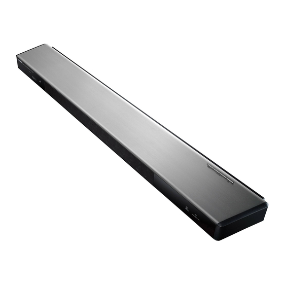
- Page 1 Digital Sound Projector Owner’s Manual Read the supplied booklet “Safety Brochure” before using the unit. English...
-
Page 2: Table Of Contents
CONTENTS FEATURES Initial settings ..........30 Displaying the menu screen on the TV . - Page 3 Yamaha’s Audio Technologies ........
-
Page 4: Features
FEATURES What you can do with this unit Sound beams are reflected off walls using unique real surround sound formats and techniques, allowing listeners to enjoy their preferred Wireless subwoofer acoustic environment. (the unit) . p. 32 • Automatically and quickly adjusts surround sound effects for the listening room setup (IntelliBeam) . -
Page 5: Preparations
• indicates precautions for use of the unit and its feature limitations. Supplied accessories Before connecting, make sure you have received all of the following items. The YSP-2500 Center unit (YSP-CU2500) Wireless subwoofer (NS-WSW120) STATUS PHONES... -
Page 6: Controls And Functions
Controls and functions Center unit (front, top) STATUS PHONES INTELLIBEAM MIC Remote control sensor PHONES jack Receives infrared signals from the remote control (p. 9). For connecting the headphones (p. 44). • When the unit is turned off, this unit consumes a small amount of Remote control sensor of a TV INTELLIBEAM MIC jack power in order to search for HDMI signals or to receive infrared... -
Page 7: Center Unit (Back)
Center unit (back) HDMI SYSTEM SUBWOOFER AUX2 OPTICAL OUT (ARC) CONNECTOR AUX1 HDMI SYSTEM SUBWOOFER AUX2 OPTICAL OUT (ARC) CONNECTOR AUX1 SYSTEM CONNECTOR jack TV/OPTICAL jacks Power cable For connecting to the supplied subwoofer using a wired For connecting to a playback device equipped with an For connecting to an AC wall outlet (p. -
Page 8: Front Panel Display
Front panel display HDMI indicator REPEATER indicator Glows when HDMI signals are input. Glows when the TV Remote Repeater function is enabled • Note that the front panel display turns off when the Eco function is (p. 15). HD indicator enabled and remains off unless an operation is performed. -
Page 9: Remote Control
Remote control ECO key CLEAR VOICE key Infrared signal transmitter Turns the Eco function on or off (p. 46). Turns the CLEAR VOICE function on or off (p. 45). SURROUND key CH LEVEL key Switches to surround playback mode (p. 40). Adjusts the volume balance during playback (p. -
Page 10: Subwoofer
Subwoofer Front Back INPUT INPUT SYSTEM CONNECTOR SYSTEM CONNECTOR SUBWOOFER PAIRING SUBWOOFER PAIRING Connection indicator SUBWOOFER PAIRING key Shows subwoofer’s connection status (p. 29). Used to pair the center unit with the subwoofer manually (p. 75). Use a pin or other pointed object to press this key. Glows green: Power on Glows red: Power off Heat discharge unit... -
Page 11: Installation
Installation This unit reflects sound beams off of walls to create the surround sound effect. The position of this unit in relation to both the listening position and walls is important to achieving the desired surround sound effects. When installing this unit on a rack behind which there is limited space, for example, it may be easier to connect external devices to this unit first. This will depend upon the installation location. -
Page 12: Example For Installing The Unit
Parallel installation Example for installing the unit Install this unit as close to the exact center of the wall as possible. This unit outputs sound beam as shown in the illustrations below. Install this unit where there are no obstacles such as furniture obstructing the path of sound beams. Otherwise, the desired surround sound effects may not be achieved. - Page 13 Installing in a non-square room Irregularly shaped rooms that are open to a hallway on one side Install this unit so that the sound beams can be reflected off the walls. Irregularly shaped rooms with solid walls on all sides •...
-
Page 14: Unrecommended Listening Environments
Example for installing the unit in living room Unrecommended listening environments • As sound beams normally pass through tables, tables are not obstacles. And a This unit creates surround sound by reflecting projected sound beams off the walls of cupboard installed facing the wall reflects sounds. your listening room. -
Page 15: (Tv Remote Repeater Function)
If the TV remote control does not work properly after the center unit is installed (TV Remote Repeater function) When the TV Remote Repeater function is enabled, the unit receives TV remote control signals at the TV remote control sensor (on front) and transmits the signals from the TV Remote Repeater (on rear). -
Page 16: Adjusting The Height Of The Center Unit
Adjusting the height of the center unit Remove the inner legs. Turn the legs counter-clockwise to increase the height of the center unit if necessary. Use a screwdriver to remove the screws. Use the arrows ( ) on the bottom of the left and right legs, and the scale on the insides of these legs, to confirm that the legs are positioned at the same height. - Page 17 ❑ Attaching the legs Attach the outer legs. Attach the innter legs. Position the outer legs so that the arrow ( ) on them points towards the rear side, and turn them clockwise to attach them. Position the inner legs so that the arrow ( ) on them points toward the rear side, and insert the protrusions into the slots on the center unit.
-
Page 18: Positioning The Subwoofer On Its Side
Positioning the subwoofer on its side The subwoofer can be laid on its side when positioned on a rack. Remove the legs and washers attached to the bottom of the Place the subwoofer on its side as shown in the illustration, and subwoofer. -
Page 19: Mounting The Center Unit On A Wall
Mounting the center unit on a wall ❑ If your TV is mounted on a wall, the optional Wall Mount Bracket SPM-K20 can be used Mounting the SPM-K20 to mount this unit on the wall under the TV. Be sure that there is enough space on the wall to mount the wall mount bracket and this See “Dimensions”... - Page 20 Attach the template supplied with this unit to the wall and use a thumbtack or pin to mark the position where screws will be inserted in the wall. Template Attach the template to the wall so that the center of The wall mount bracket is designed to be offset Once screw position has been the template is aligned with the center of the TV.
- Page 21 Connect commercial cables to this unit. • Be sure that screws are inserted in a sturdy portion of the wall or pillar. Do not mount the bracket on a wall made of materials such as mortar or veneer, which may chip or peel. If screws fall out, the wall mount bracket will also fall, resulting in damage or injury.
- Page 22 ❑ Dimensions Tighten screws. YSP-CU2500 SPM-K20 10.8 154.3 (mm) 298.3 188.3 276.8 166.8 Tighten the screws used to attach the spacer to this unit in step 4. (mm) YSP-CU2500 SPM-K20 (1.4 kg) (mm) PREPARATIONS ➤ Installation...
-
Page 23: Preparing Remote Control
Preparing remote control Before installing batteries or using the remote control, be sure to read battery and remote control precautions in “Safety Brochure” (separate booklet). Installing the batteries Operation range Battery × 2 (AAA, R03, UM-4) STATUS Press down on the arrow and slide the cover in the direction in which it points. -
Page 24: Connections
Connections When external devices such as a TV, BD/DVD player, and/or game console are connected, audio and video signals are transmitted as shown below. See pages 25 through 29 for instructions on connecting each device. Audio connection This unit: Plays audio from TV broadcasts, BD/DVD discs, etc. Video connection STATUS PHONES... -
Page 25: Connecting A Tv
Connecting a TV Connect a TV to the unit so that video input to the unit can be output to the TV. You can also enjoy playback of TV audio on the unit. • Use a 19-pin HDMI cable with the HDMI logo printed on it. A cable with a maximum length of 5 m is recommended to prevent degradation of signal quality. •... -
Page 26: Connecting Playback Devices
Connecting playback devices Connect video devices such as BD/DVD players, set-top boxes (STBs) and game consoles to the unit. Depending on the video/audio output jacks available on your video device, choose one of the following connections. We recommend using an HDMI connection if the video device has an HDMI output jack. HDMI connection Optical connection Connect a video device to the unit with an HDMI cable (not supplied). -
Page 27: Coaxial Connection
Coaxial connection Analog connection Connect a video device to this unit via a coaxial digital cable. Next, connect the video Connect a video device to this unit via a stereo cable (not supplied). Next, connect the device’s video output to the TV’s video input. video device’s video output to the TV’s video input. -
Page 28: Connecting The Power Cable
Connecting the power cable Plug in the power cable of the center unit and the subwoofer. Center unit (rear) To an AC wall outlet Subwoofer (rear) INPUT SYSTEM CONNECTOR SUBWOOFER PAIRING To an AC wall outlet PREPARATIONS ➤ Connections... -
Page 29: Connecting The Subwoofer
Connecting the subwoofer Plug the subwoofer’s power cable into a wall outlet. When the center unit is turned on, If there is no sound coming out of the subwoofer, or if sounds is intermittent, connect the center the center unit and subwoofer are automatically connected via wireless connection. unit and subwoofer via an RCA mono cable and system control cable (3.5 mm monaural mini Once the connection has been successfully established, the indicators on the center plug cable). -
Page 30: Initial Settings
Initial settings Displaying the menu screen on the TV Visual operation of this unit is The menu display TV remote control (example) possible by displaying its menu The menu is displayed on the TV screen when the SETUP ( ) key screen on the TV. -
Page 31: Selecting The Language For Menu Display
Selecting the language for menu display Turn the unit and TV on. Switch the TV’s input to display video input from this unit (p. 30). Press and hold the SETUP ( ) key until the “OSD LANGUAGE” menu appears on the TV. O S D L A N G U A G E E N G L I S H D E U T S C H... -
Page 32: Auto Setup For Appropriate Surround Effects (Intellibeam)
Auto setup for appropriate surround effects (IntelliBeam) In order for this unit to provide the optimal listening experience, adjust each channel • Use the supplied cardboard microphone stand or a tripod to place the IntelliBeam first using the “IntelliBeam” function. microphone at the same height as your ears would be when you are seated. -
Page 33: Using Auto Setup (Intellibeam)
“AUTO SETUP” in the “IntelliBeam” menu can automatically Using AUTO SETUP (IntelliBeam) adjust the following two settings. This feature optimizes the beam angle so that • It is normal for loud test tones to be output during the AUTO SETUP procedure. Beam the parameter best matches your listening Make sure that there are no children around in the listening room while the AUTO... - Page 34 Remove the IntelliBeam microphone. • The AUTO SETUP procedure takes about 3 minutes. The “AUTO SETUP COMPLETE” screen closes. • To cancel the AUTO SETUP procedure after it is started, or if you do not The IntelliBeam microphone is sensitive to heat, so should want to apply the results, press the RETURN ( ) key.
- Page 35 Press the key to select one of the items below and then press the key or ENTER key. Settings Select this optimization feature if you make BEAM+SOUND settings for the first time. This menu takes OPTIMIZE about 3 minutes. Use to optimize the beam angle so that the parameter best matches your listening BEAM OPTIMIZE ONLY environment.
-
Page 36: Error Messages
❑ If an error message is displayed If an error message is displayed on the TV screen, see “Error messages” below to determine the cause and resolve the problem. Follow the instructions displayed on the TV screen to begin measurement again. Error messages Error message Cause... -
Page 37: Operating The Unit By Tv's Remote Control (Hdmi Control)
Operating the unit by TV’s remote control (HDMI control) With some TVs, the following additional functions can be controlled. What is the HDMI control function? • Turning the UniVolume function on and off HDMI Control allows you to operate external devices via HDMI. If you connect a TV that •... -
Page 38: Setting The Hdmi Control Function
Setting the HDMI control function If the HDMI control function is not working Be sure that all devices are correctly connected to this unit, and Turn on the unit, TV, and playback devices. that settings are properly configured as described below. –... -
Page 39: Playback
PLAYBACK Basic operation for playback Input selector Press the key to turn on this unit. Press the VOL (+/-) key to adjust the volume. Press keys the SUB (+/-) key to adjust the volume of the Turn on devices (TV, BD/DVD player, game console, subwoofer. -
Page 40: Enjoying Sound Based On Your Preference
• Target playback mode (p. 44) (CINEMA DSP) • Enjoying surround sound with headphones (p. 44) Yamaha’s exclusive CINEMA DSP technology reproduces sound • Compressed Music Enhancer (p. 45) fields (sound amplitudes) for optimal surround sound playback. • CLEAR VOICE (p. 45) Press the CINEMA DSP (MOVIE, MUSIC, or •... - Page 41 ❑ CINEMA DSP options ENTERTAINMENT (use the ENTERTAINMENT key to select) MOVIE (use the MOVIE key to select) This program reproduces the energetic environment of live sports broadcasting, converging a commentator’s This program clearly reproduces dialogs and special Sports voice on the center and broadening the overall Sci-Fi sound effects of the latest science fiction films and lets atmosphere of the stadium, and lets you feel as if you are...
-
Page 42: Switching Between Audio Output Methods For Surround Playback
Switching between audio output methods for surround playback BEAM To achieve optimal surround sound effects, you can switch between sound beam output methods based on listening content or room setup. See “Sound beam output options and characteristics” (p. 43) to specify the optimal sound beam output method. - Page 43 ❑ Sound beam output options and characteristics Objective/possible Sound beam output method scenario 5BEAM+2 (5 Beam Plus 2) 5BEAM (5 Beam) Outputs sound beams from the front right and left, center, and Outputs sound beams from the front right and left, surround back right and left channels.
-
Page 44: If The Tv Remote Control Does Not Work Properly After The Center Unit Is Installed 2-Channel Playback (Stereo Playback Mode)
2-channel playback (stereo playback mode) Beam angle can be adjusted while audio or video content is playing. The front channels are the primary channel sources for output of Press the TARGET key. SURROUND stereo sound. STEREO TARGET Use the key to adjust beam angle. Press the STEREO key to switch to stereo playback mode. -
Page 45: (Compressed Music Enhancer)
Playing back digitally compressed formats Adjusting volume for each channel (such as MP3, etc.) with enriched sound Adjust the volume of playback for each channel (audio in each (Compressed Music Enhancer) direction) so that sounds are evenly distributed in their respective directions. -
Page 46: Using Useful Features
Using useful features Automatic volume level adjustment Disabling the Eco function Press the ECO key. (UniVolume) “ECO OFF” is displayed in the front panel display. Turn the UniVolume function on/off. When this function is activated, volume differences that occur when switching between input •... -
Page 47: Saving This Unit's Settings To System Memory
Saving this unit’s settings to system memory Three sets of settings can be saved to this unit’s memory, enabling • Surround playback (p. 40), stereo playback (p. 44), or target quick loading of settings optimized for specific listeners or playback mode (p. 44) environmental changes as needed. -
Page 48: Listening To The Sound From A Bluetooth Device
Perform the following steps on the Bluetooth device to be The operation varies depending on the device. Refer to the connected. instruction manual supplied with the device. Select “YSP-2500 Yamaha” in the Bluetooth device For the first Bluetooth For subsequent connection Bluetooth connection list on the device. -
Page 49: Playing Back Audio From A Bluetooth Device On The Unit
• Up to eight Bluetooth devices can be pairing with the unit. If a ninth device is • It may be necessary to select “YSP-2500 Yamaha” in the Bluetooth device list paired, the oldest pairing information is deleted. again, in the event that a connection problem occurs. You may have to change the output setting to output audio to the unit, depending on the Bluetooth device you •... -
Page 50: Using The Bluetooth Standby Mode
Using the Bluetooth standby mode Disabling Bluetooth standby mode With the unit turned on, hold down the BLUETOOTH STANDBY key for more than 3 seconds. The Bluetooth standby mode allows you to turn on (or off) the unit automatically, that coordinated by the operation of the Bluetooth device. -
Page 51: Settings
SETTINGS Setup menu A variety of settings for this unit can be specified and adjusted from the setup menu. Among the options available are the sound beam output method for optimal surround sound effects, channel volume control, and HDMI settings. The setup menu is displayed on, and operated from, the TV screen (it cannot be displayed in the front panel display). -
Page 52: Setup Menu List
Setup menu list Menu Item Function Page BEAM+SOUND OPTIMIZE Optimizes the sound beam and sound settings automatically. Optimizes the sound beam settings automatically. IntelliBeam BEAM OPTIMIZE ONLY SOUND OPTIMIZE ONLY Optimizes the sound settings automatically. HORIZONTAL ANGLE Front L, Front R, Center, Surround L, Surround R Adjust horizontal sound beam angle. -
Page 53: Beam Settings
BEAM settings • Channels that cannot be configured are displayed in grey as settings are specified as indicated in When “AUTO SETUP” in the “IntelliBeam” menu (p. 33) is used, recommended beam “Switching between audio output methods for surround playback” (p. 42). settings are automatically applied by this unit. -
Page 54: Focal Length
We recommend using the default setting (-0.5 m or -1.5 ft) for “Center”. FOCAL LENGTH Example Front left channel Center channel ➜ ➜ SETUP MENU BEAM FOCAL LENGTH With positive focal With negative focal lengths lengths Expand the optimal listening area (sweet spot). The illustration below shows how output from all channels is once concentrated in a focal point and then expanded from that point. -
Page 55: Image Location
❑ RIGHT IMAGE LOCATION The higher the percentage, the louder the output from the center channel. Once “ADJUSTMENT” has been set to “ON”, this setting can be selected. ➜ ➜ SETUP MENU BEAM IMAGE LOCATION Control range 0% (default) to 95% If sound from the left and right channels is unnatural, first adjust the volume of each channel (p. -
Page 56: Subwoofer
SOUND settings SUBWOOFER ➜ ➜ SETUP MENU BEAM SUBWOOFER CHANNEL LEVEL Specify whether or not the subwoofer’s wireless function will be used, and the distance ➜ ➜ SETUP MENU SOUND CHANNEL LEVEL from the subwoofer to the listening position. ❑ WIRELESS FUNCTION Adjust the volume of each channel to balance output levels. -
Page 57: Adaptive Drc
Adaptive DRC DYNAMIC RANGE ➜ ➜ ➜ ➜ SETUP MENU SOUND Adaptive DRC SETUP MENU SOUND DYNAMIC RANGE Adjust this unit’s volume and dynamic range for optimal balance. When “ON” is Adjust this unit’s dynamic range (difference between maximum and minimum volumes). selected, dynamic range is adjusted as follows for optimal listening at low volumes, Settings such as might be used at night. -
Page 58: Matrix Decoder
❑ About the surround decoder for playback of 5.1-channel sources MATRIX DECODER When “CHANNEL OUT” (p. 55) is set to “7.1ch”, this unit decodes 5.1-channel sources and then playback them in up to 7.1-channel surround. One of the following decoders ➜... -
Page 59: Dolby Pliix Parameter
HDMI setup Dolby PLIIx PARAMETER Use to configure the settings related to HDMI signals and the HDMI control function. Dolby PLIIx ➜ ➜ SETUP MENU SOUND PARAMETER HDMI CONTROL Adjust Dolby Pro Logic IIx Music surround decoder parameters. ➜ ➜ SETUP MENU HDMI HDMI CONTROL... -
Page 60: Tv Input
DISPLAY settings TV INPUT DIMMER ➜ ➜ SETUP MENU HDMI TV INPUT ➜ ➜ If your TV is not ARC compatible (or if the ARC feature has been disabled), TV audio is SETUP MENU DISPLAY DIMMER input via the TV (optical) jack (default). This unit’s input source can be changed to the AUX2 (coaxial) jack or AUX1 (analog) jack. -
Page 61: Osd Language
OSD LANGUAGE DISTANCE UNIT ➜ ➜ ➜ ➜ SETUP MENU DISPLAY OSD LANGUAGE SETUP MENU DISPLAY DISTANCE UNIT Use to select the language used for menus displayed on the TV screen. Use to change the display unit of measurement. Settings Settings METERS (default setting other than U.S.A. -
Page 62: Information Settings
INFORMATION settings SYSTEM Display information for the audio and video signal input to this unit. ➜ ➜ SETUP MENU INFORMATION SYSTEM AUDIO Display the version of firmware currently installed on this unit. ➜ ➜ SETUP MENU INFORMATION AUDIO The following information on the current audio input signal is displayed. Format Digital audio format The number of channels contained within the input signal—front/... -
Page 63: Settings Each Input Source (Option Menu)
Settings each input source (Option menu) Configure the functions related to the input source currently playing back content. The option menu is displayed on, and operated from, the TV screen. See “Displaying the menu screen on the TV” (p. 30) for instructions on displaying the option menu on the TV. -
Page 64: Option Menu List
Option menu list Audio delay control (AUDIO DELAY) TV images sometimes lag behind the sound. You can use this function to delay the Menu Description Input sound output to synchronize it with the video image. Adjust the output level of high (treble) HDMI1–... -
Page 65: Advanced Setup
Advanced setup The advanced setup enables more precise configuring of this unit’s function. For example, maximum volume can be specified and the INPUT key on the top panel can be disabled. Setting the advanced setup Press the z key to turn off this unit. Press the key to display the desired menu in the front panel display and then press the... -
Page 66: Advanced Setup List
Advanced setup list Menu Settings/Adjustable range Description Set the initial volume level when the power of this unit is turned on. TURN ON VOLUME OFF (Not set) (default), 1 to 70 When set to “OFF”, volume level is the same as when this unit is turned off. Set the maximum volume level so that this unit will not output sound beyond the MAX VOLUME 1 to 99, MAX (Maximum) (default) -
Page 67: Troubleshooting
Refer to the chart below when this unit does not function properly. If the problem you are experiencing is not listed below or if the instruction below does not help, turn off the unit, disconnect the AC power supply cable, and contact the nearest authorized Yamaha dealer or service center. - Page 68 Problem Cause Remedy See page No sound. Incorrect input or output cable connections. Connect the cable properly. No appropriate input source has been selected. Select an appropriate input source with the input selector keys. The volume is turned down. Turn up the volume. The sound is muted.
- Page 69 Set the function to “OFF”. subwoofer is connected using a wired connection. The subwoofer The subwoofer’s built-in protective circuit was activated. Disconnect the power cable, and contact your nearest Yamaha dealer or connection indicator service center to request repair. –...
- Page 70 Problem Cause Remedy See page The volume of low (bass) tones The volume of the subwoofer is low. Increase the volume of the subwoofer with the SUB + key. from the subwoofer is low. Content from an input source with a limited support for low tones is playing. Play content from an input source with broader support for low tones to see –...
-
Page 71: Bluetooth
Bluetooth Problem Cause Remedy See page Cannot make the unit paired with Bluetooth is not selected as the input source. Select Bluetooth as the input source. the Bluetooth device. The device does not support A2DP. Perform paring operations with a device which supports A2DP. A Bluetooth adaptor, etc. -
Page 72: Remote Control
Remote control Problem Cause Remedy See page The remote control does not work The wrong distance or angle. The remote control functions within a maximum range of 6 m (20 ft) and no and/or function properly. more than 30 degrees off-axis from the front panel. Direct sunlight or lighting (from an inverter type of fluorescent lamp, etc.) is Reposition this unit. -
Page 73: When Surround Effect Is Not Enough
When surround effect is not enough The unit achieves its surround sound effects by projecting sound beams which reflect Installing and adjusting the sound reflection board off walls. The sound beams are not reflected toward to the listening position caused by YRB-100 furniture, etc., in the path of sound beams, or the room shape. - Page 74 Use advanced setup (p. 65) to configure the sound Plug the IntelliBeam microphone into this unit and reflection board. then perform “AUTO SETUP” (BEAM+SOUND OPTIMIZE) from the “IntelliBeam” menu (p. 33). Set “YRB FL” (FL), “YRB FR” (FR), “YRB SL” (SL), and “YRB SR”...
-
Page 75: Pairing The Center Unit And The Subwoofer
Pairing the center unit and the subwoofer • Be sure that “WIRELESS FUNCTION” in the setup menu is set to “ON” (p. 56). Pairing is the process of establishing a wireless connection between the center unit and subwoofer. When the center unit is turned on for the first time, the center unit and subwoofer are usually paired automatically. If a problem occurs (e.g., the TX indicator does not glow), follow the instructions below to pair the center unit and subwoofer manually. -
Page 76: Appendix
Surround sound offers the sense of being surrounded by sounds, an A digital sound projector separately controls compact speakers This unit features many more functions based on Yamaha’s superior experience common in concert halls and movie theaters. This can be installed in orderly rows, so that optimized audio signals are output audio technologies. -
Page 77: Glossary
Glossary Sampling Frequency and Bit Depth Dolby Pro Logic IIx HDMI These are values that represent the amount of information used to This technology converts not only audio recorded in 2 channels, but High-Definition Multimedia Interface (HDMI) is a digital audio/video convert analog signals to digital signals. -
Page 78: Specifications
Specifications YSP-CU2500 Bluetooth NS-WSW120 • Bluetooth version..........Ver. 2.1 +EDR • Driver...........10 cm (4 in) cone woofer × 2 Amplifier section non-magnetic shielding type • Supported protocols ..........A2DP, SPP • Rated Output Power • INPUT jack ................1 Tweeter (1 kHz, 1% THD, 4 Ω) ........27.2 W •... - Page 79 ” logo and “IntelliBeam” are trademarks of Yamaha The Bluetooth® word mark and logos are registered trademarks Corporation. owned by Bluetooth SIG, Inc. and any use of such marks by Yamaha Corporation is under license. Other trademarks and trade names are those of their respective owners.
-
Page 80: Available Signal Information
Available signal information ❑ Repeatable video signals HDMI signal compatibility This unit is compatible with the following video signals. ❑ Receivable audio signals • Deep Color • x.v.Color Audio signal types Audio signal formats Compatible media • 3D video signal 2ch Linear PCM 2ch, 32–192 kHz, 16/20/24 bit CD, DVD-Video, DVD-Audio, etc. -
Page 81: Index
Index Numerics Compressed Music Enhancer 45 3BEAM (3 Beam) 43 HD indicator 8 5.1ch 43, 58 HDMI 77 Deep Color 77 5BEAM (5 Beam) 43 HDMI audio assignment 64 DIMMER 60 5BEAM+2 (5 Beam Plus 2) 43 HDMI AUDIO OUT 59 DISTANCE 56 7.1ch 43 HDMI CONTROL 37, 59... - Page 82 Pairing 48 UniVolume 46 Power cable 7, 10, 24 UNIVOLUME indicator 8 Pulse Code Modulation (PCM) 77 Video signal information 62 Rear panel (center unit) 7 VOL indicator 8, 39 Rear panel (subwoofer) 10 Volume 39 Remote control 9, 23 VOLUME TRIM 64 Remote control sensor 6 REPEATER indicator 8...
- Page 83 © 2014 Yamaha Corporation YG376A0/EN...
Need help?
Do you have a question about the YSP-2500 and is the answer not in the manual?
Questions and answers