Table of Contents
Advertisement
MICRO COMPONENT SYSTEM
DRX-730/
This manual has been provided for the use of authorized YAMAHA Retailers and their service personnel.
It has been assumed that basic service procedures inherent to the industry, and more specifi cally YAMAHA Products, are already known
and understood by the users, and have therefore not been restated.
WARNING:
IMPORTANT:
The data provided is believed to be accurate and applicable to the unit(s) indicated on the cover. The research, engineering, and service
departments of YAMAHA are continually striving to improve YAMAHA products. Modifications are, therefore, inevitable and
specifi cations are subject to change without notice or obligation to retrofi t. Should any discrepancy appear to exist, please contact the
distributor's Service Division.
WARNING:
IMPORTANT:
■ CONTENTS
TO SERVICE PERSONNEL ........................................2-4
REGION MANAGEMENT INFORMATION .....................6
SYSTEM COMPOSITION ................................................6
FRONT PANELS .............................................................7
REAR PANELS ...........................................................8-9
REMOTE CONTROL PANELS .......................................9
SPECIFICATIONS ................................................... 10-11
INTERNAL VIEW .......................................................... 12
SERVICE PRECAUTIONS ...................................... 13-14
DISASSEMBLY PROCEDURES ............................. 15-16
1 0 1 1 1 9
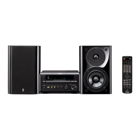
The MCR-730 consists of the DRX-730 and the NX-E700.
IMPORTANT NOTICE
Failure to follow appropriate service and safety procedures when servicing this product may result in personal injury,
destruction of expensive components, and failure of the product to perform as specifi ed. For these reasons, we advise
all YAMAHA product owners that any service required should be performed by an authorized YAMAHA Retailer or
the appointed service representative.
The presentation or sale of this manual to any individual or fi rm does not constitute authorization, certifi cation or
recognition of any applicable technical capabilities, or establish a principle-agent relationship of any form.
Static discharges can destroy expensive components. Discharge any static electricity your body may have
accumulated by grounding yourself to the ground buss in the unit (heavy gauge black wires connect to this buss).
Turn the unit OFF during disassembly and part replacement. Recheck all work before you apply power to the unit.
Copyright © 2008
This manual is copyrighted by YAMAHA and may not be copied or
redistributed either in print or electronically without permission.
MCR-730
NX-E700
SERVICE MANUAL
UPDATING FIRMWARE .......................................... 17-23
SELF-DIAGNOSTIC FUNCTION ............................24-36
DISPLAY DATA .............................................................37
IC DATA ...................................................................38-43
BLOCK DIAGRAMS ................................................44-45
PRINTED CIRCUIT BOARDS .................................46-51
PIN CONNECTION DIAGRAMS ...................................52
SCHEMATIC DIAGRAMS .......................................53-55
REPLACEMENT PARTS LIST ................................57-69
REMOTE CONTROL ...............................................70-71
All rights reserved.
P.O.Box 1, Hamamatsu, Japan
animate '08.11
Advertisement
Table of Contents

Related Manuals for Yamaha MCR-730


Summary of Contents for Yamaha MCR-730
-
Page 1: Table Of Contents
This manual has been provided for the use of authorized YAMAHA Retailers and their service personnel. It has been assumed that basic service procedures inherent to the industry, and more specifi cally YAMAHA Products, are already known and understood by the users, and have therefore not been restated. -
Page 2: To Service Personnel
DRX-730/NX-E700 ■ TO SERVICE PERSONNEL AC LEAKAGE 1. Critical Components Information WALL EQUIPMENT TESTER OR Components having special characteristics are marked OUTLET UNDER TEST EQUIVALENT must be replaced with parts having specifications equal to those originally installed. 2. Leakage Current Measurement (For 120V Models Only) When service has been completed, it is imperative to verify INSULATING that all exposed conductive surfaces are properly insulated... - Page 3 DRX-730/NX-E700 WARNING: Laser Safety This product contains a laser beam component. This component may emit invisible, as well as visible radiation, which may cause eye damage. To protect your eyes and skin from laser radiation, the following precautions must be used during servicing of the unit. 1) When testing and/or repairing any component within the product, keep your eyes and skin more than 30 cm/1 feet away from the laser pick-up unit at all times.
- Page 4 DRX-730/NX-E700 U, C models T, K, A, G, F, L, V models Warning for power supply The primary side of the power supply carries live mains voltage when the player is connected to the mains even when the player is switched off ! This primary area is not shielded so it is possible to accidentally touch copper tracks and/or components when servicing the player.
-
Page 5: Prevention Of Electrostatic Discharge
DRX-730/NX-E700 ■ PREVENTION OF ELECTROSTATIC DISCHARGE Some semiconductor (solid state) devices can be damaged easily by static electricity. Such components commonly are called Electrostatically Sensitive (ES) Devices. Examples of typical ES devices are integrated circuits and some field-effect transistors and semiconductor “chip” components. The following techniques should be used to help reduce the incidence of component damage caused by electro static discharge (ESD). -
Page 6: Region Management Information
Macrovision Corporation. Reverse engineering or disassembly is prohibited. ■ SYSTEM COMPOSITION The MCR-730 consists of the DRX-730 and the NX-E700. ▼ NX-E700 ▼ NX-E700 ▼ DRX-730 Color variations:... -
Page 7: Front Panels
DRX-730/NX-E700 ■ FRONT PANELS DRX-730 (U, C, T, K, A, G, F, L, V models) Top view NX-E700 (U, C, T, K, A, G, F, L, V models) -
Page 8: Rear Panels
DRX-730/NX-E700 ■ REAR PANELS DRX-730 (U, C models) DRX-730 (G model) DRX-730 (T model) DRX-730 (F model) DRX-730 (K model) DRX-730 (L model) DRX-730 (A model) DRX-730 (V model) -
Page 9: Remote Control Panels
DRX-730/NX-E700 NX-E700 U, C, K, A, G, F, L, V models T model T model ■ REMOTE CONTROL PANELS U, C, K, A, L, V models G, F models... -
Page 10: Specifications
DRX-730/NX-E700 ■ SPECIFICATIONS DRX-730 ■ Amplifier Section Maximum Power (JEITA, 6 ohms, 1 kHz, 10 % THD) Pb Output/Component Video Output SP OUT ............30 W + 30 W ...............0.7 Vp-p (75 ohms) Minimum RMS Output Power (6 ohms, 1 kHz, 0.9 % THD) Pr Output/Component Video Output SP OUT ............ -
Page 11: Specifications
DRX-730/NX-E700 NX-E700 ■ Speaker Section U .......U.S.A. model G ....European model C ....Canadian model F ....Russian model Type ......... 2-way bass reflex speaker system T ....Chinese model L ....Singapore model Magnetic shielding type K ..... Korean model V ..... Taiwan model A ....Australian model Driver Woofer ...........11 cm (4-1/2") cone type... -
Page 12: Internal View
DRX-730/NX-E700 ■ INTERNAL VIEW Top view AM/FM TUNER MAIN (2) P.C.B. (G, F models) DVD MODULE P.C.B. SUB (1) P.C.B. MAIN (1) P.C.B. SUB (2) P.C.B. DVD MECHANISM ASS’Y... -
Page 13: Service Precautions
DRX-730/NX-E700 ■ SERVICE PRECAUTIONS When DVD MODULE P.C.B. of this unit is replaced, the serial number and new ID number (device key) must be reported to YCJ (Yamaha Corporation Japan) by email. (Fig. 1) Email: ycav-keycontrol@gmx.yamaha.com ycav-keycontrol@gmx.yamaha.com ycav-keycontrol@gmx.yamaha.com Model name... - Page 14 DRX-730/NX-E700 ● Check the New ID Number (Device key) Connection Connect the VIDEO OUT terminal of this unit to the VIDEO IN terminal of the TV monitor with a video pin cable. Operation Procedure Perform following steps while watching the TV monitor screen and using the keys of this unit. 1.
-
Page 15: Disassembly Procedures
DRX-730/NX-E700 ■ DISASSEMBLY PROCEDURES (Remove parts in the order as numbered.) 3. Removal of DVD Mechanism Ass’y and DVD Disconnect the power cable from the AC outlet. Module P.C.B. a. Remove 4 screws ( ) and screw ( ). (Fig. 1) 1. - Page 16 DRX-730/NX-E700 ● How to manually eject the disc tray a. Move the slider in the direction indicated in the figure below with a screwdriver until the disc tray is ejected. (Fig. 2) Note: An Allen hex socket screwdriver 2.5 mm is recommended for this operation. b.
-
Page 17: Updating Firmware
DRX-730/NX-E700 ■ UPDATING FIRMWARE Writing to the microprocessor After replacing the following parts update the latest firmware according to the following procedure. MAIN P.C.B. Microprocessor (IC11) of MAIN P.C.B. ● Required tools ● Preparation and precautions before starting the operation •... - Page 18 DRX-730/NX-E700 ● Connection 1. Set the switch (SW301) of RS232C conversion adapter to the “FLASH UCOM” side. 2. Connect the writing port of this unit to the serial port (RS232C) of the PC with RS232C cross cable, RS232C con- version jig and flexible flat cable as shown below. (Fig. 1) Rear side Front side "STANDBY/ON"...
- Page 19 DRX-730/NX-E700 5. Click [Refer...]. And select the firmware name. (Fig. 3) The ID code and MCU type are loaded automatically when the file is selected. (Fig. 3) Click [OK]. (Fig. 3) Click to open the window Fig. 3 6. Click [E.P.R.], the screen appears as shown below. (Fig. 4) Click [OK] to start writing.
- Page 20 DRX-730/NX-E700 7. When the program transmission is completed, the screen appears as shown below. (Fig. 5) Click [OK] to end the procedure. (Fig. 5) Fig. 5 8. Using the self-diagnostic function menu, check that the firmware is updated successfully. When the displayed firmware version and checksum are different from written ones, perform the “Writing to the microprocessor”...
- Page 21 DRX-730/NX-E700 Writing to the Module Board After replacing the Module board with the replacement part, be sure to write the latest firmware. ● Required Tools Firmware CD To make the firmware CD, download the latest firmware from the specified download source to PC. When making a firmware CD, set the CD volume label to “PIONEER”.
- Page 22 DRX-730/NX-E700 7. Move the cursor to [Options] by pressing the “DOWN” key on the remote control repeatedly and press the “ON SCREEN” key. (Fig. 7) The ROM version is displayed. (Fig. 7) Remote control This unit "ON SCREEN" key "STANDBY/ON" key Initial Settings Digital Audio Out Parental Lock...
- Page 23 DRX-730/NX-E700 ● Operation Procedures CAUTION: Do not turn off the power while updating the firmware. 1. Connect the VIDEO OUT terminal of this unit to the VIDEO IN terminal of the TV monitor with a video pin cable. 2. Connect the power cable of this unit to the AC outlet. 3.
-
Page 24: Self-Diagnostic Function
DRX-730/NX-E700 ■ SELF-DIAGNOSTIC FUNCTION This unit has self-diagnostic function that are intended for inspection, measurement and location of faulty point. There are 11 main menu items, each of which has sub-menu items. Listed in the table below are menu items and sub-menu items. MAIN MENU SUB MENU 1 VERSION/SUM... - Page 25 DRX-730/NX-E700 ● Starting Self-Diagnostic Function While pressing those 2 keys of this unit as indicated in the figure below, press the “STANDBY/ON” key to turn on the power. The self-diagnostic function mode is activated. Keys of this unit Turn on the power while pressing these keys. ●...
- Page 26 DRX-730/NX-E700 ● Display provided when Self-Diagnostic Function started The FL display of this unit displays the protection function history data then the main menu (sub-menu VERSION/CHECK SUM of main menu No. 1 FIRMWARE VERSION) a few seconds later. When there is no history of protection function: Opening message Main menu display When there is no protection history...
- Page 27 DRX-730/NX-E700 ● Operation procedure of Main menu and Sub-menu There are 11 menu items, each of having sub-menu items. Main menu selection Select the menu using “ ” (Forward) and “ ” (Reverse) keys of this unit. Sub-menu selection Select the sub-menu using“ ”...
- Page 28 DRX-730/NX-E700 ● Details of Self-Diagnostic Function menu 1. FIRMWARE VERSION The firmware version, checksum, destination, CPU type etc. are displayed. The checksum is obtained by adding the data at every 8 bits (1 byte) for each program area and expressing the result as a 4-figure hexadecimal data.
- Page 29 DRX-730/NX-E700 3. VOLUME CHECK This menu is used to check the volume level setting. VOLUME MIN. 3 . V O L U M E M I N VOLUME -20dB 3 . V O L U M E - 2 0 d B VOLUME MAX.
- Page 30 DRX-730/NX-E700 4. DISPLAY CHECK This menu is used to check the FL display section. The display condition varies as shown below according to the sub-menu operation. Checking FL display section Initial display Initial display All segments OFF All segments OFF All segments ON (dimmer 100%) All segments ON (dimmer 100%) All segments ON (dimmer 50%)
- Page 31 * 10 k-ohms, 1/4 W ⎪ Other ⎭ pull down Bluetooth adapter version The firmware version of the YBA-10 (YAMAHA) connected to the DOCK is displayed. 5 . B T V : - - - - - - - -...
- Page 32 DRX-730/NX-E700 6. MUTE CHECK This menu is used to select the MUTE status of HP (phones) / SW. MUTE 6 . M U T E O F F The MUTE function of HP (phones) and SW (subwoofer) is turned OFF. HP MUTE 6 .
- Page 33 DRX-730/NX-E700 8. AD DATA CHECK This menu is used to display the A/D conversion value of the microprocessor which detects panel keys of this unit and protection functions in using the sub-menu. When KEY menu is selected, keys become non-operable due to detection of the values of all keys. However, it is possible to advance to the next sub-menu by turning the INPUT of this unit.
- Page 34 DRX-730/NX-E700 KEY (K0) When the A/D value of the panel key becomes out of the specified range, 8 . K E Y : 5 0 0 normal operation will not be available. Check each panel key for the constant of the voltage dividing resistance, soldered condition, etc, referring to the table below.
- Page 35 DRX-730/NX-E700 10. POWER OFF FACTOR HISTORY The 5 power OFF factor histories are displayed. Power OFF factor history 1 1 0 - 1 N O H I S T O R Y Power OFF factor history 2 1 0 - 2 N O H I S T O R Y Power OFF factor history 3 1 0 - 3 N O H I S T O R Y Power OFF factor history 4...
- Page 36 DRX-730/NX-E700 11. DVD SETTING This mode is prepared mainly for manufacturing use. D V D W R I T E I D I D W r i t e E n t 0 1 D V D C L E A R I D D V D R E W R I T E F / W Select “DVD CLEAR ID”...
-
Page 37: Display Data
DRX-730/NX-E700 ■ DISPLAY DATA ● V801 : 16-BT-133GNK (SUB P.C.B.) PATTERN AREA ● PIN CONNECTION Pin No. Connection Pin No. Connection Note : 1) F1, F2 ..Filament 2) NP ..No pin 3) NX ..No extended Pin 4) 1G − 16G ..Grid 5) NC .. -
Page 38: Ic Data
DRX-730/NX-E700 ■ IC DATA IC11: R5F3640DNFA (MAIN P.C.B.) Single-chip 16-bit Microprocessor Port P0 Port P1 Port P2 Port P3 Port P4 Port P5 VCC2 ports Internal peripheral functions Clock generation circuit UART or clock synchronous serial I/O Timer (16-bit) (6-channels) COUT PLL frequency synthesizer Outputs (timer A): 5... - Page 39 DRX-730/NX-E700 Function Name Port Name Detail of Function Pulldown Pulldown XREADY DVD module I/F ready signal output XDVDRST DVD module I/F reset output DVD module HDMI power supply ON/OFF output DVDPOWER (H: power on, L: power off) PS protection detection for iPod power source iPod_PRT (H: when normal, L: when abnormal) Pulldown...
- Page 40 DRX-730/NX-E700 Function Name Port Name Detail of Function * Pulldown 41 EPM * Connect to GND via resistor (for Flash writing) required (47 k-ohms) VIDEO YUV/RGB selection output -> unused VIDEO mute output (H: mute off, L: mute on) 43 VMUTE DVD/USB input selection: mute off setting 44 SCL_VOL Selector/Volume I2C clock output...
- Page 41 DRX-730/NX-E700 Function Name Port Name Detail of Function 83 LED_P LED output PROGRESSIVE (H: lit) 84 LED_T LED output TIMER (H: lit) 85 IREB Encoder input INPUT 86 IREA Encoder input INPUT 87 VREB Encoder input VOLUME 88 VREA Encoder input VOLUME 89 KEY0 P107 A-D IN AD KEY input...
- Page 42 DRX-730/NX-E700 IC801: M66003-0131FP (SUB P.C.B.) FL display driver Display code CGROM SEG00 (35 bit x 166) (8-bit x 60) SEG25 Segment Code output write SEG26 circuit CGROM SEG34 dot data Serial data (35 bit x 16) write receive Code/ circuit SDATA command SEG35...
- Page 43 DRX-730/NX-E700 Function Port Name Detail of Function Name RESET /RESET Reset input When “L”, M66003 is initialized. /CEFL Chip select input When “L”, communication with the MCU is possible. CKFL Shift clock input When “H”, any instruction from the MCU is neglected. SDATA DTFL Serial data input Serial input data is taken and shifted by the positive edge of SCK.
-
Page 44: Block Diagrams
DRX-730/NX-E700 ■ BLOCK DIAGRAM AUDIO/VIDEO SECTION BLOCK DIAGRAM Q3,4 12,13 AUX OUT R2A15908SP Input selector MUTE AUX IN Phones HPMT • See page 55 → SCHEMATIC DIAGRAM DOCK IC21 SUBWOOFER MUTE 1,10 FM/AM SWMT TUNER FM/AM (G, F models) IC26 AUDIO DAC SPEAKER L PCM1753... -
Page 45: Block Diagrams
DRX-730/NX-E700 POWER SUPPLY SECTION BLOCK DIAGRAM • See page 54 → • See page 53 → MAIN SCHEMATIC DIAGRAM SCHEMATIC DIAGRAM IC10 BD9778HFP D501 IGND T501 +20D +12FL,+12V,+12A KIA7812API SW501 IC502 Q501 +10T,+9A,+9B KIA7809API Control AC IN -20D +5,+5A,+5FL,+5D KIA78M05 IC506 IC15 V+5V... -
Page 46: Printed Circuit Boards
POINT A XL2 (Pin 11 of IC11) POINT B XL3 (Pin 13 of IC11) DRX-730/NX-E700 DVD MODULE (CN968) ■ PRINTED CIRCUIT BOARDS -20D -20D AGND AGND +20D MAIN (1) P.C.B. (Side A) +20D PAGND PGND • Semiconductor Location VGND Ref no. Location Ref no. - Page 47 DRX-730/NX-E700 MAIN (1) P.C.B. (Side B) • Semiconductor Location Ref no. Location T, K, A, G, F, L, V models IC10 IC12 IC15 IC15 IC12 IC10 U, C, T, K, A, L, V models MAIN (2) P.C.B. (Side B) G, F models G, F models G, F models...
- Page 48 DRX-730/NX-E700 SUB (1) P.C.B. (Side A) MAIN (1) T, K, A, G, L, F models U, C, V models (CB19) CGND PWR_RY AC IN +5SUB +12_RES VGND PGND PAGND +20D +20D AGND AGND -20D -20D MAIN (1) (CB18) +15DD +15DD MGND DGND FGND...
- Page 49 DRX-730/NX-E700 SUB (1) P.C.B. (Side B) T, K, A, G, L, F models IC502 K A R • Semiconductor Location T, K, A, G, L, F models Ref no. Location D503 D508 D509 D512 D517 D518 D519 D521 IC502 IC505...
- Page 50 DRX-730/NX-E700 SUB (2) P.C.B. (Side A) • Semiconductor Location Ref no. Location TIMER indicator D809 D810 D812 HDMI indicator PROGRESSIVE indicator OPEN/ CLOSE PLAY/ STOP PAUSE PHONES PORTABLE CB807 VOLUME INPUT CB801 STANDBY/ CB806 MAIN (1) (CB12) MAIN (1) (CB20)
- Page 51 DRX-730/NX-E700 SUB (2) P.C.B. (Side B) • Semiconductor Location Ref no. Location D801 D802 D803 D804 D811 IC801 Q801 Q802 Q803 Q804 Q805 Q806 Q807...
-
Page 52: Pin Connection Diagrams
DRX-730/NX-E700 ■ PIN CONNECTION DIAGRAMS • ICs • Diodes 74AHCT541PW TSSOP BA50DD0WHFP BD9302FP-E2 BD9778HFP 1SR154-400 1SS355 D1NL20U-5083 D5SBA60 D1NL40-7083 D1FK60-5063 1SS380 RB051L-40 Anode Anode ANODE – Cathode Cathode CATHODE KIA78L05F-RTF/P KIA78M05F KIA7809API-U/P L6566BTR KIA7812API R2A15908SP D5S9M MA8030 3.0V MTZJ22D P6KE200ARL MA8039-H 4.0V MA8051-M 5.1V MA8062-M 6.2V... -
Page 53: Schematic Diagrams
DRX-730/NX-E700 SCHEMATIC DIAGRAMS MAIN To TUNER DVD IN IC26 IC26 ANALOG OUT -20.2 -12.0 20.2 11.5 19.9 IC27: KIA78L05F-RTF/P -20.5 -8.0 Three terminal positive voltage regulator -17.0 -20.2 -20.5 INPUT -11.5 -19.9 20.2 12.0 -20.2 IC21 IC21 -20.2 -10.2 -10.2 AUX IN 19.8 OUTPUT... - Page 54 DRX-730/NX-E700 SUB 1/2 20.2 128.9 332.1 331.9 Page 53 129.0 330.8 to MAIN (1)_CB18 431.8 W501 431.7 331.5 -2.2 -20.5 20.2 10.0 -20.5 -20.5 14.6 14.6 14.6 332.1 12.8 CB501 IC506 -2.2 AC IN CONTROL CB502 CB503 -3.2 IC503 -27.0 14.6 -27.0 Page 53...
- Page 55 DRX-730/NX-E700 SUB 2/2 11.5 -22.1 -22.2 -17.2 -20.6 -14.2 -18.9 -16.1 IC801 -22.2 -17.2 -22.3 -17.2 -17.5 VOLUME INPUT -22.2 -20.6 -20.6 -20.3 JK801 PORTABLE JK802 Page 53 to MAIN (1)_CB20 PHONES IC801: M66003-0131FP-R 18 digit 5 x 7 segment VFD controller/driver Display code CGROM (35-bit x 166)
-
Page 56: Replacement Parts List
DRX-730/NX-E700 ■ REPLACEMENT PARTS LIST • ELECTRICAL COMPONENT PARTS WARNING ● Components having special characteristics are marked and must be replaced with parts having specifications equal to those originally installed. ● The chip resistor is not supplied as a replacement part. When a chip resistor is necessary, use the following part. - Page 57 DRX-730/NX-E700 P.C.B. MAIN Ref No. Part No. Description Markets Ref No. Part No. Description Markets WQ228200 P.C.B. MAIN C76-77 US135100 C.CE.CHP 0.1uF WQ228300 P.C.B. MAIN C78-82 UR866100 C.EL WQ228400 P.C.B. MAIN UR847100 C.EL 10uF WQ228500 P.C.B. MAIN C84-85 UA352220 C.MYLAR 220pF WQ228600 P.C.B.
- Page 58 DRX-730/NX-E700 P.C.B. MAIN Ref No. Part No. Description Markets Ref No. Part No. Description Markets C162 UR848100 C.EL 100uF C249-250 VE326800 C.MYLAR 0.47uF C163 US135100 C.CE.CHP 0.1uF C251 UR848100 C.EL 100uF C164 US065100 C.CE.CHP 0.1uF 50V B C252-253 US065100 C.CE.CHP 0.1uF 50V B C165...
- Page 59 DRX-730/NX-E700 P.C.B. MAIN and P.C.B. SUB Ref No. Part No. Description Markets Ref No. Part No. Description Markets X9799A00 IC R2A15908SP R115 WB785000 R.MTL.OXD 18 Ω 1W J X7889A00 IC PCM1753DBQR R176 HV754100 R.CAR.FP 10 Ω 1/4W X8235A00 IC LC72725KM R180 HV754100 R.CAR.FP 10 Ω...
- Page 60 DRX-730/NX-E700 P.C.B. SUB Ref No. Part No. Description Markets Ref No. Part No. Description Markets C527 WN934600 C.EL 1500uF IC503 WP388200 PHOT.CPL TLP781(D4-GR,F) C528 WG348200 C.EL 33uF 100V IC505 X6770A00 IC NJM431U(TE1) C529 VR169200 C.MYLAR 0.47uF IC506 WP388200 PHOT.CPL TLP781(D4-GR,F) C533 WD969200 C.CE.CHP 0.1uF...
- Page 61 DRX-730/NX-E700 • OVERALL ASS'Y MAIN UNIT FRONT PANEL UNIT 200-1 U, C, L, V models K, A, G, F models...
-
Page 62: Remote Control
DRX-730/NX-E700 Ref No. Part No. Description Remarks Markets WP302500 TOP COVER WP302700 TOP COVER WP302600 TOP COVER SI, WH WP305700 WP305900 WP305800 SI, WH WP303100 KNOB D32 WP303300 KNOB D32 WP303200 KNOB D32 SI, WH WP302800 KNOB D19 WP303000 KNOB D19 WP302900 KNOB D19 SI, WH... - Page 63 DRX-730/NX-E700 • FRONT PANEL UNIT 1-116 1-117 1-116 1-115 1-103 1-110 1-117 1-116 1-109 1-11 1-108 1-12 1-111 1-104 1-115 1-102 1-103 1-101...
- Page 64 DRX-730/NX-E700 Ref No. Part No. Description Remarks Markets 1-11 WQ277200 FLEXIBLE FLAT CABLE 6P 90mm P=1.0 1-12 WQ277800 FLEXIBLE FLAT CABLE 30P 90mm P=1.0 1-101 WP300400 FRONT PANEL 1-101 WP300600 FRONT PANEL 1-101 WP300500 FRONT PANEL SI, WH 1-102 WP303500 SUB PANEL 1-102 WP303700...
- Page 65 DRX-730/NX-E700 • MAIN UNIT 2-33 2-31 2-34 2-121 2-121 2-36 2-122 2-35 2-124 2-22 2-32 2-124 2-102 2-123 2-38 2-6-1 2-124 2-1 (2) 2-123 2-124 2-11 2-12 DVD Mechanism Ass'y 2-2 (1) 2-121 2-121 2-121 2-1 (1) 2-115 2-121 2-121 2-103 2-124 2-103...
- Page 66 DRX-730/NX-E700 Ref No. Part No. Description Remarks Markets WQ228200 P.C.B. ASS'Y MAIN WQ228300 P.C.B. ASS'Y MAIN WQ228400 P.C.B. ASS'Y MAIN WQ228500 P.C.B. ASS'Y MAIN WQ228600 P.C.B. ASS'Y MAIN WQ228700 P.C.B. ASS'Y MAIN WQ228800 P.C.B. ASS'Y MAIN WQ229000 P.C.B. ASS'Y WQ229100 P.C.B.
- Page 67 DRX-730/NX-E700 NX-E700 • OVERALL ASS'Y 1-12 TWEETER 2.7ohms/5W 3.3uF/63V WOOFER INPUT 1.0mH Ref No. Part No. Description Remarks Markets WG237700 CABINET ASS'Y Black color GD, BL, SI WM884000 CABINET ASS'Y White color 1-12 V9909600 HOLDER WG237800 FRONT GRILLE ASS'Y Black color GD, BL, SI WM884100 FRONT GRILLE ASS'Y...
- Page 68 DRX-730/NX-E700 Carbon Resistors Value 1/4W Type Part No. 1/6W Type Part No. Value 1/4W Type Part No. 1/6W Type Part No. 1.0 Ω 3100 3100 11 kΩ 7110 7110 HJ35 HF85 HF45 HF45 ✻ 1.8 Ω 3180 12 kΩ 7120 7120 HJ35 HJ35...
-
Page 69: Remote Control
DRX-730/NX-E700 ■ REMOTE CONTROL SCHEMATIC DIAGRAM PANEL U, C, K, A, L, V models KEY No. 2 ohms (1/4W) 47μF 27 ohms 2SC3440-T112 VDD CARR IC1: M34283G2GP-W5/U1 Z-N0102-86214#1X Not mount XIN XOUT 3.0V 4MHz G, F models... - Page 70 DRX-730/NX-E700 KEY NO. LAYOUT KEY CODE Label (English) Label (English) Custom Data Custom Data Code Code Code Code Upper Case Upper Case STANDBY/ON TOP MENU/INFO. OPEN/CLOSE MENU ENTER SET UP RETURN AUTO/MANUAL MEMORY VOLUME+ ZOOM BAND ON SCREEN TUNER AUDIO VOLUME- SUBTITLE DVD/USB...
- Page 71 DRX-730/ NX-E700...
Need help?
Do you have a question about the MCR-730 and is the answer not in the manual?
Questions and answers