Yamaha YAS-207 Service Manual
Front surround system
Hide thumbs
Also See for YAS-207:
- Owner's manual (424 pages) ,
- Update manual (7 pages) ,
- Owner's manual (424 pages)
Table of Contents
Advertisement
FRONT SURROUND SYSTEM
CENTER UNIT
WIRELESS SUBWOOFER
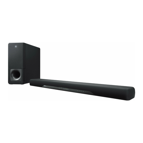
The YAS-207/ATS-2070 consists of the YAS-CU207/ATS-CU2070 and NS-WSW42.
YAS-207 は、YAS-CU207 および NS-WSW42 で構成されています。
Notes: • When accepting a repair order from the user, it is recommended to receive the YAS-CU207/ATS-CU2070
and NS-WSW42 as a set for the repair work.
• Turning on the power to YAS-CU207/ATS-CU2070 makes wireless connection of YAS-CU207/ATS-CU2070
and NS-WSW42 possible. After the repair work, if their wireless connection is not made automatically, makes
it possible manually. (For details, refer to "PAIRING THE CENTER UNIT AND SUBWOOFER MANUALLY".)
注意: ・ ユーザーから修理依頼を受ける際、YAS-CU207 と NS-WSW42 をセットでお預かりすることを推奨します。
・ YAS-CU207 の電源をオンにすると YAS-CU207 と NS-WSW42 は自動的に無線接続されます。修理完了後、
電源を入れても自動的に無線接続されない場合は手動で無線接続を完了してください。 (詳細は "センター
ユニットとサブウーファーを手動でペアリングする" を参照してください。 )
This manual has been provided for the use of authorized Yamaha Retailers and their service personnel.
It has been assumed that basic service procedures inherent to the industry, and more specifi cally Yamaha Products, are already known
and understood by the users, and have therefore not been restated.
WARNING:
IMPORTANT:
The data provided is believed to be accurate and applicable to the unit(s) indicated on the cover. The research, engineering, and service
departments of Yamaha are continually striving to improve Yamaha products. Modifi cations are, therefore, inevitable and specifi cations
are subject to change without notice or obligation to retrofi t. Should any discrepancy appear to exist, please contact the distributor's
Service Division.
WARNING:
IMPORTANT:
■ CONTENTS
TO SERVICE PERSONNEL ............................................2
SYSTEM COMPOSITION / システム構成 .......................4
PANEL LAYOUTS ...........................................................5
REMOTE CONTROL PANELS ..................................... 11
SPECIFICATIONS / 参考仕様 ....................................... 12
INTERNAL VIEW .......................................................... 15
SERVICE PRECAUTIONS / サービス時の注意事項 ..... 16
DISASSEMBLY PROCEDURES / 分解手順 ................. 17
UPDATING FIRMWARE /
ファームウェアのアップデート ..................................26
1 0 1 3 9 6
YAS-CU207/ATS-CU2070
SERVICE MANUAL
IMPORTANT NOTICE
Failure to follow appropriate service and safety procedures when servicing this product may result in personal injury,
destruction of expensive components, and failure of the product to perform as specifi ed. For these reasons, we advise
all Yamaha product owners that any service required should be performed by an authorized Yamaha Retailer or the
appointed service representative.
The presentation or sale of this manual to any individual or fi rm does not constitute authorization, certifi cation or
recognition of any applicable technical capabilities, or establish a principle-agent relationship of any form.
Static discharges can destroy expensive components. Discharge any static electricity your body may have
accumulated by grounding yourself to the ground buss in the unit (heavy gauge black wires connect to this buss).
Turn the unit OFF during disassembly and part replacement. Recheck all work before you apply power to the unit.
PROTECTION DISPLAY / プロテクションの表示 ........29
BLOCK DIAGRAMS ......................................................31
WIRING DIAGRAM .......................................................35
PRINTED CIRCUIT BOARDS .......................................36
CIRCUIT DIAGRAMS ....................................................39
REPLACEMENT PARTS LIST ......................................46
REMOTE CONTROL .....................................................49
センターユニットとサブウーファーを手動でペアリングする .....50
Copyright (c) Yamaha Corporation All rights reserved.
This manual is copyrighted by Yamaha and may not be copied or
redistributed either in print or electronically without permission.
YAS-207/ATS-2070
NS-WSW42
P.O.Box 1, Hamamatsu, Japan
'17.06
Advertisement
Table of Contents

Related Manuals for Yamaha YAS-207


Summary of Contents for Yamaha YAS-207
-
Page 1: Table Of Contents
This manual has been provided for the use of authorized Yamaha Retailers and their service personnel. It has been assumed that basic service procedures inherent to the industry, and more specifi cally Yamaha Products, are already known and understood by the users, and have therefore not been restated. -
Page 2: To Service Personnel
YAS-CU207/ATS-CU2070/NS-WSW42 ■ TO SERVICE PERSONNEL AC LEAKAGE WALL EQUIPMENT TESTER OR 1. Critical Components Information OUTLET UNDER TEST EQUIVALENT Components having special characteristics are marked ⚠ and must be replaced with parts having specifications equal to those originally installed. 2. Leakage Current Measurement (For 120V Models Only) When service has been completed, it is imperative to verify INSULATING that all exposed conductive surfaces are properly insulated... - Page 3 YAS-CU207/ATS-CU2070/NS-WSW42 WARNING: Lithium batteries CAUTION 注意 Danger of explosion if battery is incorrectly replaced. 正しい電池と交換しないと爆発が起きるおそれがありま Replace only with the same or equivalent type. す。 同一型名または同等品以外の電池とは絶対に交換しない ようにしてください。 WARNING: ADVARSEL! Lithium batteries are dangerous because they can be exploded by improper handling. Observe the Lithiumbatteri –Eksplosionsfare ved fejlagtig håndtering.
-
Page 4: System Composition / システム構成
YAS-CU207/ATS-CU2070/NS-WSW42 ■ SYSTEM COMPOSITION / システム構成 The YAS-207/ATS-2070 consists of the YAS-CU207/ATS- YAS-207 は、YAS-CU207 および NS-WSW42 で構成されて CU2070 and NS-WSW42. います。 YAS-207 ▼ NS-WSW42 ▼ YAS-CU207 ATS-2070 ▼ NS-WSW42 ▼ ATS-CU2070... -
Page 5: Panel Layouts
YAS-CU207/ATS-CU2070/NS-WSW42 ■ PANEL LAYOUTS YAS-CU207 ATS-CU2070 Top view Front view YAS-CU207 U, C, T, K, A, B, G, V models J model ATS-CU2070 Rear view U, C, T, K, A, B, G, V models J model Bottom view Labels... - Page 6 YAS-CU207/ATS-CU2070/NS-WSW42 Labels YAS-CU207 U, C models A model T model B model K model G model...
- Page 7 YAS-CU207/ATS-CU2070/NS-WSW42 V model J model ATS-CU2070 U model B model A model G model...
- Page 8 YAS-CU207/ATS-CU2070/NS-WSW42 NS-WSW42 Top view Rear view...
- Page 9 YAS-CU207/ATS-CU2070/NS-WSW42 Rear view U, C models T model K model A model...
- Page 10 YAS-CU207/ATS-CU2070/NS-WSW42 B model G model V model J model...
-
Page 11: Remote Control Panels
YAS-CU207/ATS-CU2070/NS-WSW42 ■ REMOTE CONTROL PANELS FSR78 FSR77 (U, C, T, K, A, B, G, V models) (J model) -
Page 12: Specifications / 参考仕様
................2.7 kg (6 lbs.) ..............SBC, MPEG4 AAC Finish / 仕上げ RF Output Power / 無線出力 [YAS-207] ................ Bluetooth class 2 U, C, T, K, A, B, G, V, J models ......Black color [ATS-2070] Maximum Communication Range / 最大通信距離... - Page 13 Impedance / インピーダンス ..................2 ohms The Bluetooth ® word mark and logos are registered trademarks owned by Bluetooth SIG, Inc. and any use of such marks by Yamaha Corporation is ■ Wireless Section / 無線部 under license. Bluetooth ®...
- Page 14 YAS-CU207/ATS-CU2070/NS-WSW42 • DIMENSIONS / 寸法図 YAS-CU207 ATS-CU2070 Unit: mm (inch) 単位 : mm(インチ) Top view Side view min 20 4–6 (3/4") (1/8–1/4") Front view (1/8") 930 (36-5/8") (4-1/4") 7–9 (1/4"–3/8") Rear view 279 (11") 290 (11-3/8") (1") Mounting hole size 457 (18") ネジ掛け穴サイズ...
-
Page 15: Internal View
YAS-CU207/ATS-CU2070/NS-WSW42 ■ INTERNAL VIEW YAS-CU207 ATS-CU2070 Top view Front view Rear view SUB (USB) P.C.B. DRIVER TWEETER MAIN P.C.B. SUB (LED) P.C.B. POWER SUPPLY UNIT SUB (AC) P.C.B. DRIVER FULL-RANGE (FRONT L/R) SUB (JACK) P.C.B. NS-WSW42 Top view Rear view DRIVER WOOFER AMP P.C.B. -
Page 16: Service Precautions / サービス時の注意事項
YAS-CU207/ATS-CU2070/NS-WSW42 ■ SERVICE PRECAUTIONS / サービス時の注意事項 Operation check 動作確認 NS-WSW42 NS-WSW42 NS-WSW42 does not operate by itself. NS-WSW42 は単独で動作しません。 To check its operation, prepare the YAS-CU207/ATS- 動作確認をする場合、YAS-CU207 を用意してください。 CU2070. Precaution for handling measuring instrument 計測機器取り扱い上の注意 YAS-CU207/ATS-CU2070 YAS-CU207 Since the speaker output of this unit is BTL connected, 本機のスピーカー出力は... -
Page 17: Disassembly Procedures / 分解手順
YAS-CU207/ATS-CU2070/NS-WSW42 ■ DISASSEMBLY PROCEDURES / 分解手順 (Remove parts in the order as numbered.) (番号順に部品を外してください。 ) Disconnect the power cable from the AC outlet. AC 電源コンセントから、電源コードを抜いてください。 YAS-CU207 ATS-CU2070 Removal of Bottom Cabinet Assembly 1. ボトムキャビネット Ass'y の外し方(Fig. 1) (Fig. 1) Spread a rubber sheet and cloth for protection of a. ... - Page 18 YAS-CU207/ATS-CU2070/NS-WSW42 How to Remove Parts Installed 2. ボトムキャビネット Ass'y に to the Bottom Cabinet Assembly 取り付けてあるパーツの外し方 2-1. Removal of Driver Full-Range (Fig. 2) 2-1. スピーカーユニット(フルレンジ)の外し方 (Fig. 2) The driver removal procedure is the same for ※ スピーカーユニットの外し方は左右同じです。 both right and left. a. ...
- Page 19 YAS-CU207/ATS-CU2070/NS-WSW42 2-3. Removal of SUB (JACK) P.C.B. (Fig. 3) 2-3. SUB(JACK)P.C.B. の外し方(Fig. 3) Remove 2 screws ( ④ ). a. ④ のネジ 2 本を外します。 Remove CN200. b. CN200 を外します。 Remove the SUB (JACK) P.C.B. b. SUB(JACK)P.C.B. を外します。 2-4. Removal of SUB (USB) P.C.B. (Fig. 3) 2-4. ...
- Page 20 YAS-CU207/ATS-CU2070/NS-WSW42 2-5. Removal of MAIN P.C.B. (Fig. 4) 2-5. MAIN P.C.B. の外し方(Fig. 4) Remove 6 screws ( ⑥ ). a. ⑥ のネジ 6 本を外します。 Remove CN100 and CON2. b. CN100、CON2 を外します。 Remove the MAIN P.C.B. c. MAIN P.C.B. を外します。 2-6. Removal of Power Supply Unit (Fig. 4) 2-6. ...
- Page 21 YAS-CU207/ATS-CU2070/NS-WSW42 2-7. Removal of SUB (AC) P.C.B. (Fig. 5) 2-7. SUB(AC)P.C.B. の外し方(Fig. 5) Remove 2 screws ( ⑧ ). a. ⑧ のネジ 2 本を外します。 Remove the SUB (AC) P.C.B. b. SUB(AC)P.C.B. を外します。 2-8. Removal of SUB (LED) P.C.B. (Fig. 5) 2-8. SUB(LED)P.C.B. の外し方(Fig. 5) Remove the SUB (LED) P.C.B.
- Page 22 YAS-CU207/ATS-CU2070/NS-WSW42 NS-WSW42 1. Removal of Side Frame Assembly 1. サイドフレーム Ass'y、フロントフレーム Ass'y and Front Frame Assembly (Fig. 1) の外し方(Fig. 1) The side frame assembly is fixed to the cabinet with ※ サイドフレーム Ass'y は 16 箇所のダボで、また、フロ dowels at 16 locations and the front frame assembly ントフレーム...
- Page 23 YAS-CU207/ATS-CU2070/NS-WSW42 2. Removal of Driver Subwoofer (Fig. 2) 2. スピーカーユニットの外し方(Fig. 2) a. Remove 6 screws ( ① ), and pull out the driver subwoofer. a. ① のネジ 6 本を外し、スピーカーユニットを引き出し ます。 b. Disconnect the connector connected to the terminal of the driver subwoofer. b. ...
- Page 24 YAS-CU207/ATS-CU2070/NS-WSW42 3. Removal of Rear Panel Assembly (Fig. 3) 3. リアパネル Ass'y の外し方(Fig. 3) a. Remove 6 screws ( ② ). a. ② のネジ 6 本を外します。 Screws ( ② ) are identified with arrow marks ( ). ※ 取り外す ② のネジには矢印( )が印刷されてい ます。 b. Remove the rear panel assembly. b. ...
- Page 25 YAS-CU207/ATS-CU2070/NS-WSW42 4. Removal of AMP P.C.B. (Fig. 4) 4. AMP P.C.B. の外し方(Fig. 4) a. Remove 4 screws ( ③ ). a. ③ のネジ 4 本を外します。 b. Remove CON2. b. CON2 を外します。 c. Remove the AMP P.C.B. together with the P.C.B. support. c. AMP P.C.B. を P.C.B. サポートと一緒に外します。 5.
-
Page 26: ファームウェアのアップデート
YAS-CU207/ATS-CU2070/NS-WSW42 ■ UPDATING FIRMWARE / ファームウェアのアップデート When the following part is replaced, the firmware must be 下記の部品を交換した場合、ファームウェアを最新バー updated to the latest version. ジョンにアップデートする必要があります。 MAIN P.C.B. MAIN P.C.B. ● Confirmation of firmware version ● ファームウェアのバージョンの確認 It is not possible to check the firmware version ※ ... - Page 27 YAS-CU207/ATS-CU2070/NS-WSW42 ● Operation Procedures ● 操作手順 Disconnect the power cable of this unit from the ※ 本機の電源コードを AC コンセントから抜きます。 AC outlet. 1. Insert the USB storage device to the UPDATE ONLY 1. アップデート専用端子に USB フラッシュメモリー jack. (Fig. 1) を差し込みます。 (Fig. 1) 2.
- Page 28 YAS-CU207/ATS-CU2070/NS-WSW42 If writing of the firmware has failed, disconnect ※ ファームウェアの書き込みに失敗した場合、 the power cord from the AC outlet and perform 電源コードを AC コンセントから抜き、ファー the firmware updating procedure again from ムウェアのアップデートを最初からやり直し the beginning. てください。 5. When writing of the firmware is completed, all 5. ...
-
Page 29: Protection Display / プロテクションの表示
DD / DTS” indicator indicates the causal factor of “ DD / DTS” インジケーターを使って、プロテクション the protection function. の要因が表示されます。 ● Protection Display ● プロテクションの表示 This unit / 本機 (front view / 前側 ) YAS-207 U, C, T, K, A, B, G, V models J model ATS-2070 indicator インジケーター Flashing pattern 点滅パターン... - Page 30 YAS-CU207/ATS-CU2070/NS-WSW42 MEMO...
-
Page 31: Block Diagrams
YAS-CU207/ATS-CU2070/NS-WSW42 YAS-CU207 ATS-CU2070 ■ BLOCK DIAGRAMS All Section Block Diagram • See page 44 → • See page 39–42 → MAIN ENABLED INPUT CIRCUIT DIAGRAM CIRCUIT DIAGRAM IC202 Hi-Z (JACK) 3.3V NORMAL DSP FW FAULTZ OUTPUT BY25Q32ASSIG FAULT Audio in update port Audio in ANALOG... - Page 32 YAS-CU207/ATS-CU2070/NS-WSW42 YAS-CU207 ATS-CU2070 Power Supply Section Block Diagram IC101 BT MODULE DC 3.3V REG CSR8670 S1:EN Pmax:50W Pmax:50W BL9198-33BAPRN Ptyp:15W (1/3 power) Ptyp:15W (1/3 power) Imax:10.843mA Imax:10.85mA INPUT VOLTAGE: Imax:10.8mA INPUT VOLTAGE: DC:3.1V–3.6V DC:2–6V Ityp:9.04mA Ityp:9mA Ityp:9.036mA OUTPUT CURRENT: IC200 Imax:300mA 2.0C APPLE AUTH.
- Page 33 YAS-CU207/ATS-CU2070/NS-WSW42 NS-WSW42 All Section Block Diagram 26MHz PCB ANT. Y801 2402MHz-2480MHz B3V3 Analog Signal BT MODULE GPIO CSRA65700 B3V3 DC Power Supply IC803 Digital Bus EEPROM GT24C128A Digital Audio Analog Audio B3V3 STANDBY M3V3 IC810 IC809 indicator OP AMP LED4 B3V3 DIO2032 PCM5100A...
- Page 34 YAS-CU207/ATS-CU2070/NS-WSW42 NS-WSW42 Power Supply Section Block Diagram IC805 POWER AMPLIFIER Imax:5.3A TPA3116D2 2 ohms Ityp:1.6A Pmax:100W Ptyp:30W (1/3 power) INPUT VOLTAGE: VCC:4.5V–26V IC807 IC804 DC 3.3V REG BL9198-33BAPRN STM8S003F3 Imax:14.5mA Imax:4.5mA Ityp:8.7mA INPUT VOLTAGE: Ityp:3.7mA INPUT VOLTAGE: DC:2–6V DC:2.95–5.5V OUTPUT CURRENT: Imax:300mA PC:0.4W DC:3.3V...
-
Page 35: Wiring Diagram
YAS-CU207/ATS-CU2070/NS-WSW42 YAS-CU207 ATS-CU2070 NS-WSW42 ■ WIRING DIAGRAM Center Unit SUBWOOFER Unit L ch MAIN AC INLET SUBWOOFER (AC) LED/Touch Panel/RMC receiver CN600 (LED) TWEETER OPTICAL TWEETER AC IN INPUT INPUT Power supply unit SMPS P.C.B. (JACK) CN603 DC OUT HDMI HDMI OUTPUT INPUT... -
Page 36: Printed Circuit Boards
YAS-CU207/ATS-CU2070/NS-WSW42 YAS-CU207 ATS-CU2070 ■ PRINTED CIRCUIT BOARDS FOR INFORMATION ONLY (COMPONENT PARTS NOT AVAILABLE) SUB (USB) (CN606) MAIN (Side A) TWEETER HDMI FULL-RANGE DRIVERS (FRONT L/R) (ARC) TWEETER Power supply unit Note: Precaution for handling measuring instrument SUB (JACK) Since the speaker output of this unit is BTL connected, the ground side (CN603) of the measuring instrument to be connected to the speaker terminal MUST be kept in floating condition. - Page 37 YAS-CU207/ATS-CU2070/NS-WSW42 YAS-CU207 ATS-CU2070 (Side A) (LED) (Power) (Side B) (LED) CLEAR BASS SURROUND BLUETOOTH ANALOG HDMI DD/DTS VOICE EXTENSION MAIN (CN100) (Side A) (Side B) (JACK) (JACK) (Side A) (Side B) MAIN (CN200) (AC) (AC) ANALOG AC IN (Side A) (Side B) (USB) (USB)
- Page 38 YAS-CU207/ATS-CU2070/NS-WSW42 NS-WSW42 (Side A) (Side A) (AC) AC IN DRIVER SUBWOOFER Power supply unit Power supply unit (Side B) (Side B) (AC) PAIRING STANDBY indicator indicator Writing port...
-
Page 39: Circuit Diagrams
YAS-CU207/ATS-CU2070/NS-WSW42 YAS-CU207 ATS-CU2070 ■ CIRCUIT DIAGRAMS FOR INFORMATION ONLY (COMPONENT PARTS NOT AVAILABLE) MAIN 1/4 YAS-207 CENTER UNIT_MCU SECTION * R162 * R133 VERSION G, B others VERSION DGND DGND [4/4] +5VA +5V_IN [4/4] AC_DET AC_DET [4/4] R177 100K AMP_SDZ... - Page 40 YAS-CU207/ATS-CU2070/NS-WSW42 YAS-CU207 ATS-CU2070 MAIN 2/4 YAS-207 CENTER UNIT_DSP&BT SECTION AUTO STANDBY AAC FUNCTION DESTINATON DEFAULT DESTINATON DEFAULT G, B ENABLED EXCEPT G, B DISABLED EXCEPT J CN200 PH-6 OPTICAL_IN GNDD R220 C252 C256 DGND 3V3A VCC3.3V C253 C257 3.3V R219 C209 4.7uF...
- Page 41 YAS-CU207/ATS-CU2070/NS-WSW42 YAS-CU207 ATS-CU2070 MAIN 3/4 YAS-207 CENTER UNIT_HDMI SECTION MGLB3216M161T5R0-LF FB300 160R IC300 NR3015-2R2NC TPS562201DDCR C341 L300 R316 2.2uH1.85A 0.1uF PIN8,11,16,20. D_1V32 FB301 120R VDD1V3 VBST C305 R301 7.5K1% Fsw=580KHz CN304 P300 P301 R300 SHIELDIGN CASE R302 10K1% CN302 CN303...
- Page 42 YAS-CU207/ATS-CU2070/NS-WSW42 YAS-CU207 ATS-CU2070 MAIN 4/4 YAS-207 CENTER UNIT_AMPLIFIER SECTION DC/DC 5V Rt=150K Fsw=658KHz SNRH1005R-150M MGLB3216M161T5R0-LF L400 FB401 C408 R407 15uH3.6A 160R 0.1u16V IC400 EML3193B-00SG08NR D401 MGLB3216M161T5R0-LF 6.8V CN400 F400 FB400 XH-6P 0468001NR 160R +22V +22V R447 Note: 1A/63V COMP R400 Precaution for handling measuring instrument 0.3R/7+7W...
- Page 43 YAS-CU207/ATS-CU2070/NS-WSW42 YAS-CU207 ATS-CU2070 SUB (LED) CN600 FFC_1.0mm_H SCL1 R614 330R SDA1 330R R613 Page 39 RST1 R612 470R 470R to MAIN_CN100 R671 DET. Indicators VCC1 FB605 600R VCC1A LED_VCC 3.3V R624 R625 R626 DEBUG D604 C626 0.1uF R608 R611 620R 220R1% R616 R600...
- Page 44 YAS-CU207/ATS-CU2070/NS-WSW42 YAS-CU207 ATS-CU2070 SUB (JACK, USB, AC) CN603 SAN-6P_H OPT_IN R635 OPT_IN1 100R CN601 DGND1 SPDIF-IN C601 3V3_1 FB603 Page 40 3.3V 600R DGND R_CH to MAIN_CN200 OPTICAL-IN C602 C603 0.1uF 4.7uF CN605 AC-OUT AC SOCKET AC600 R636 AC 90~264V CN602 50/60Hz to Power supply unit...
- Page 45 YAS-CU207/ATS-CU2070/NS-WSW42 NS-WSW42 (AC) CN605 AC-OUT AC SOCKET AC600 AC 90~264V to Power supply unit 50/60Hz AMP, SUB (AC) AC IN AC-OUT AC INLET BOARD AC601 (AC) L804 R828 B3V3 IC805 FB600 C847 0.1uF C818 TPA3116D2 0603 C814 C821 0.1uF R860 PVCC_22V 0.1uF 2.2uF...
-
Page 46: Replacement Parts List
YAS-CU207/ATS-CU2070/NS-WSW42 YAS-CU207 ATS-CU2070 ■ REPLACEMENT PARTS LIST • OVERALL ASSEMBLY Note: About sponge/EVA packing * 注意: インシュレーター/パッキンについて * The “sponge” and “EVA packing” used at each location of this unit are not supplied individually. 本機の各箇所に使用されている インシュレーター 、 パッキン は個別に供給しません。 “sponge 700 x 25 x 2”... - Page 47 MAIN with Bluetooth ATS-CU2070 640-AS2072-020X0 G PCB MAIN ZZ068300 P.C.B. ASSEMBLY MAIN with Bluetooth 640-YS2072-250X0 V PCB MAIN * 11 ZZ069500 BOTTOM CABINET YAS-207 300-N02942-010X0 J ボトムキャビネット * 11 ZZ069400 BOTTOM CABINET YAS-207 300-N02942-000X0 UCTKABGV ボトムキャビネット * 11 ZZ069600 BOTTOM CABINET ATS-2070 300-N02942-030X0 UABG ボトムキャビネット...
- Page 48 YAS-CU207/ATS-CU2070/NS-WSW42 NS-WSW42 • OVERALL ASSEMBLY Ref No. Part No. Description Remarks Markets 部 品 名 * 301 ZZ061200 SCREW 3x10 372-B30100-BTNX2 ネジ * 302 ZZ061800 REAR PANEL 20-4303-02-01-X0 J リアパネル * 302 ZZ061700 REAR PANEL 20-4303-01-01-X0 UC リアパネル * 302 ZZ062200 REAR PANEL 20-4303-06-01-X0 T リアパネル...
-
Page 49: Remote Control
YAS-CU207/ATS-CU2070/NS-WSW42 ■ REMOTE CONTROL ● FSR78: U, C, T, K, A, B, G, V models ● FSR77: J model CIRCUIT DIAGRAM KEY NO. LAYOUT KEY CODE Key Name Key Code (U, C, T, K, A, B, G, V models) (J model) Custom Data (Power) -
Page 50: Pairing The Center Unit And Subwoofer Manually
YAS-CU207/ATS-CU2070/NS-WSW42 ■ PAIRING THE CENTER UNIT AND SUBWOOFER MANUALLY Turn off the unit. Within 30 seconds, press and hold the PAIRING YAS-CU207/ATS-CU2070 button on the rear panel of the subwoofer Press and hold the SUBWOOFER (–) key on the for more than 3 seconds. remote control for more than 3 seconds.
Need help?
Do you have a question about the YAS-207 and is the answer not in the manual?
Questions and answers