
Related Manuals for Black Box ACX1004


Summary of Contents for Black Box ACX1004
-
Page 1: User Manual
User Manual Edition: 2011-01-19 ServSwitch TC Model: ACX1004 ACX1008 Black Box Deutschland GmbH Ludwigstrasse 45 b 85399 Hallbergmoos techsupp@black-box.de www.blackbox.de Tel. +49 811 5541 0 Fax +49 811 5541 499... - Page 2 ServSwitch TC Copyright © 2011. All rights reserved. This information may not be reproduced in any manner without the prior written consent of the manufacturer. Information in this document is subject to change without notice. Trademarks All trademark and trade names mentioned in this document are acknowledged to be the property of their respective owners.
-
Page 3: Table Of Contents
System Overview ..............7 Product Range ..............9 Upgrade Kits ............... 9 Accessories ................. 9 Device Views ..............10 3.6.1 Model ACX1004 ..........10 3.6.2 Model ACX1008 ..........11 Status LEDs ..............12 Installation .................. 14 Package Contents ............. 14 System Setup .............. - Page 4 ServSwitch TC Specifications ................20 Interfaces ................20 7.1.1 USB-HID ............. 20 7.1.2 RJ10 / 4P4C ............21 Supported Peripherals ............21 7.2.1 USB-HID Devices ..........21 Connector Pinouts ............22 Power Supply ..............23 Environmental Conditions ..........23 Size ................... 23 Shipping Weight ..............
-
Page 5: About This Manual
About This Manual About This Manual Scope This manual describes how to install your ServSwitch TC, how to operate it and how to perform trouble shooting. Validity This manual is valid for all devices listed on the front page. The product code is printed on the base of the devices. -
Page 6: Safety Instructions
ServSwitch TC Safety Instructions To ensure reliable and safe long-term operation of your ServSwitch TC please note the following guidelines: Installation Only use in dry, indoor environments. The ServSwitch TC and the power supply units can get warm. Do not situate them in an enclosed space without any airflow. -
Page 7: Description
Description Description Application The ServSwitch TC is used to handle several sources (computer, CPU, KVM Extender CON Units) and several monitors with one keyboard and mouse set only. The ServSwitch TC is especially suitable for use with KVM switches and KVM extenders of the ServSwitch TC family. - Page 8 ServSwitch TC Sources (computer, CPU, KVM Extender CON Units) ServSwitch TC Keyboard, mouse See Chapter 4.3, Page 15 for installation examples. 2011-10-04...
-
Page 9: Product Range
Description Product Range Model Description ACX1004 ServSwitch TC 4 Port ACX1008 ServSwitch TC 8 Port Upgrade Kits Model Description ACS2209A-RMK 19"/1U rack mount kit to mount up to 2 devices ACS4001A-DRM Mounting plate to mount by snap on Accessories Model... -
Page 10: Device Views
ServSwitch TC Device Views 3.6.1 Model ACX1004 10 11 12 Rear View Connect to RJ10 / 4P4C (Port 1) To CPU 1: USB-HID Connect to RJ10 / 4P4C (Port 2) To CPU 2: USB-HID Connect to RJ10 / 4P4C (Port 3) -
Page 11: Model Acx1008
Description 3.6.2 Model ACX1008 13 14 15 16 17 18 19 20 10 11 12 Rear View Connect to RJ10 / 4P4C (Port 1) To CPU 1: USB-HID Connect to RJ10 / 4P4C (Port 2) To CPU 2: USB-HID Connect to RJ10 / 4P4C (Port 3) To CPU 3: USB-HID Connect to RJ10 / 4P4C (Port 4) To CPU 4: USB-HID... -
Page 12: Status Leds
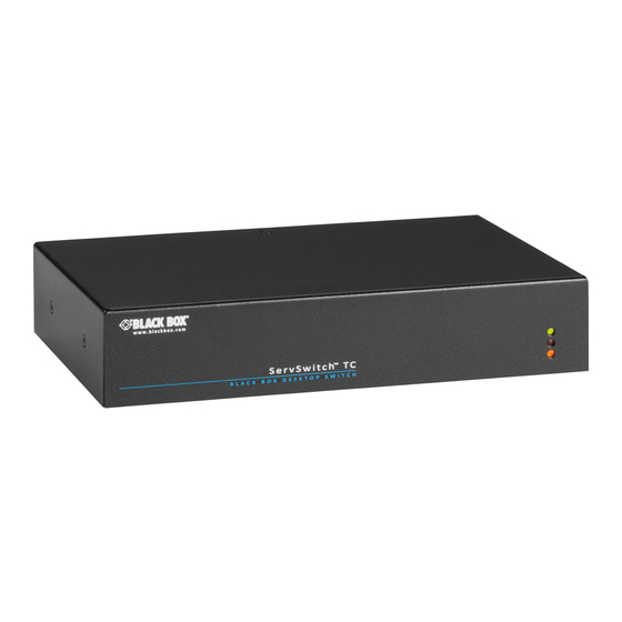
ServSwitch TC Status LEDs The ServSwitch TC is fitted with a multi color LED on both sides for indication of connection status: Front View Pos. LED Status Description Device not ready Status (green) Device ready Power supply not available Power (red) Power supply available 2011-10-04... - Page 13 Description Rear View Pos. LED Status Description No connection to CPU 1 USB Status CPU 1 (green) Connection to CPU 1 No connection to CPU 2 USB Status CPU 2 (green) Connection to CPU 2 No connection to CPU 3 USB Status CPU 3 (green) Connection to CPU 3...
-
Page 14: Installation
ServSwitch TC Installation Package Contents Your extender package contains the following items: 5VDC international power supply unit German power cord Quick Setup 4x USB cable (1.8 m, type A to type B) Additional content for ACX1008: ... -
Page 15: Example Applications
Installation Example Applications This section illustrates typical installations of the ServSwitch TC: ServSwitch TC (Direct CPU connection) Source (computer, CPU) Switch button (see Chapter 5.3, Page 18) ServSwitch TC Keyboard, mouse 2011-10-04... - Page 16 ServSwitch TC ServSwitch TC (In combination with ServSwitch DKM) ServSwitch DKM CON Units Monitor LEDs (see Chapter 5.2, Page 18) ServSwitch TC Keyboard, mouse 2011-10-04...
-
Page 17: Configuration
Configuration Configuration Command Mode The ServSwitch TC has a Command Mode that allows several functions via keyboard command during normal use. To enter Command Mode use a 'Hot Key' sequence and to exit Command Mode, press <Esc>. While in Command Mode, the LEDs Shift and Scroll on the console keyboard will flash. -
Page 18: External Display (Optional)
ServSwitch TC In a KVM switch configuration, choose different 'Hot Keys' for the KVM Extender and the ServSwitch TC ServSwitch TC. External Display (optional) The ServSwitch TC has a RJ10 interface at each USB-HID port for CPUs (see Chapter 7.1.2, Page 21). It provides the current status of the port, e.g. -
Page 19: Operation
Operation Operation Switching a Source 6.1.1 Switching via Keyboard From your console, you can switch via keyboard sequence between different monitors. Open Command Mode with the 'Hot Key' (see Chapter 5.1, Page 17). Enter the number of the specific source or monitor and confirm with <Enter>. -
Page 20: Specifications
ServSwitch TC Specifications Interfaces 7.1.1 USB-HID Our devices with an USB-HID interface support a maximum of two devices compliant with the USB-HID protocol. Each USB-HID port provides a maximum current of 100 mA. Keyboard Compatible with most USB keyboards. Certain keyboards with additional functions may require custom firmware to operate. -
Page 21: Rj10 / 4P4C
Specifications 7.1.2 RJ10 / 4P4C This interface is used to establish a customer specific communication with the ServSwitch TC. External Status LED For control of an external Status LED to show the status of the respective port, please proceed as follows: Connect the anode of your LED with pin 1 and the cathode with pin 2. -
Page 22: Connector Pinouts
ServSwitch TC Connector Pinouts Connector USB Type B Picture Signal Color VCC (+5VDC) Data – White Data + Green Black Connector USB Type A Picture Signal Color VCC (+5VDC) Data – White Data + Green Black Connector Mini USB Type B Picture Signal Color... -
Page 23: Power Supply
Inside VCC (+5VDC) Outside Power Supply Voltage 5 VDC Power Requirement ACX1004: max. 500 mA ACX1008: max. 700 mA Environmental Conditions Operating Temperature 41 to 113°F (5 to 45°C) Storage Temperature –13 to 140°F (–25 to 60°C) Relative Humidity Max. -
Page 24: Troubleshooting
ServSwitch TC Troubleshooting USB-HID Diagnosis Possible Reason Measure Press <Esc> to leave Command Keyboard LEDs Keyboard in Command Shift and Scroll Mode Mode. are flashing Connect USB-HID device. USB device No USB-HID device without function Check compatibility. USB-HID device is not supported ... -
Page 25: Technical Support
Technical Support Technical Support Prior to contacting support please ensure you have read this manual, and then installed and set-up your ServSwitch TC as recommended. Support Checklist To efficiently handle your request it is necessary to complete our checklist for support and problem cases (Blackbox Tech Support). Keep the following information available before you call: ... -
Page 26: Regulatory And Standards Compliance
Council Directive on the approximation of the laws of the Member States relating to electromagnetic compatibility CE Marking 2009 Product list: ACX1004, ACX1008 The products comply with the following harmonized standards for Information Technology Equipment: EN 55022: 09/2006 (Class A) -
Page 27: North American Regulatory Compliance
Regulatory and Standards Compliance 10.2 North American Regulatory Compliance This equipment has been found to comply with the limits for a Class A digital device, pursuant to Part 15 of the FCC Rules. These limits are designed to provide reasonable protection against harmful interference when the equipment is operated in a commercial environment. -
Page 28: Glossary
ServSwitch TC Glossary The following terms are commonly used in this guide or in video and KVM technology: Term Explanation Cat X Any Cat 5e (Cat 6, Cat 7) cable The Color Graphics Adapter (CGA) is an old analog graphic standard with up to 16 displayable colors and a maximum resolution of 640x400 pixels. - Page 29 Glossary Term Explanation The Enhanced Graphics Adapter (EGA) is an old analog graphic standard, introduced by IBM in 1984. A D-Sub 9 connector is used for connection. FBAS The analog color video baseband signal (FBAS) is also called Composite Video and it is part of the PAL TV standard.
- Page 30 ServSwitch TC Term Explanation USB-HID USB-HID devices (Human Interface Device) allow for data input. There is no need for a special driver during installation; "New USB-HID device found" is reported. Typical HID devices include keyboards, mice, graphics tablets and touch screens. Storage, video and audio devices are not HID.
Need help?
Do you have a question about the ACX1004 and is the answer not in the manual?
Questions and answers