Toa A-903MK2 Operating Instructions Manual
900 series ii mixer power amplifiers
Hide thumbs
Also See for A-903MK2:
- Operating instructions manual (12 pages) ,
- Specifications (4 pages) ,
- Manual (28 pages)
Table of Contents
Advertisement
900 series
MIXER POWER AMPLIFIERS
TABLE OF CONTENTS
1. IMPORTANT SAFETY INSTRUCTIONS ..... 2
2. SAFETY PRECAUTIONS ............................ 3
3. GENERAL DESCRIPTION .......................... 5
4. FEATURES .................................................. 5
5. NOMENCLATURE AND FUNCTIONS ........ 6
6.1. Module Installation ................................ 8
6.2. Speaker Connections ............................ 9
6.3. Remote Control Connections .............. 11
Thank you for purchasing TOA's 900 Series
Please carefully follow the instructions in this manual to ensure long, trouble-free use of your equipment.
IN P
U T
1
IN P
U T
2
B A
IN P
S S
U T
3
T R
IN P
E B
U T
L E
4
9 0
T O
0 S
N E
IN P
U T
E R
D E
F E
5
IE S
A T
A M
P L IF
L O
IE R
O F
W
IN P
F
C U
U T
A -
T
O N
6
9 0
3 M
K 2
O F
F
IN P
O N
U T
7
IN P
U T
8
Mixer Power Amplifier.
OPERATING INSTRUCTIONS
S IG
N A
L
N O
R M
A L
P E
P R
A K
O T
M A
E C
S T
T
E R
P O
W E
R
O N
O F
F
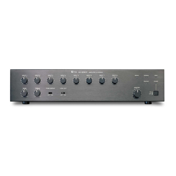
This figure represents the A-903MK2.
8. OPERATION .............................................. 13
9. VOLUME CONTROL COVER ................... 13
10.1. A-903MK2 ......................................... 14
10.2. A-906MK2, A-912MK2 ...................... 14
11.1. A-903MK2 ......................................... 15
11.2. A-906MK2, A-912MK2 ...................... 16
A-903MK2
A-906MK2
A-912MK2
Advertisement
Table of Contents

Subscribe to Our Youtube Channel
Related Manuals for Toa A-903MK2


Summary of Contents for Toa A-903MK2
-
Page 1: Table Of Contents
6.2. Speaker Connections ......9 11.2. A-906MK2, A-912MK2 ...... 16 6.3. Remote Control Connections ....11 Thank you for purchasing TOA's 900 Series Mixer Power Amplifier. Please carefully follow the instructions in this manual to ensure long, trouble-free use of your equipment. -
Page 2: Important Safety Instructions
1. IMPORTANT SAFETY INSTRUCTIONS • Read these instructions. • Keep these instructions. • Heed all warnings. • Follow all instructions. • Do not use this apparatus near water. • Clean only with dry cloth. • Do not block any ventilation openings. Install in accordance with the manufacturer's instructions. •... -
Page 3: Safety Precautions
• Should the following irregularity be found during use, immediately switch off the power, disconnect the power supply plug from the AC outlet and contact your nearest TOA dealer. Make no further attempt to operate the unit in this condition as this may cause fire or electric shock. - Page 4 Indicates a potentially hazardous situation which, if mishandled, could CAUTION result in moderate or minor personal injury, and/or property damage. When Installing the Unit • Never plug in nor remove the power supply plug with wet hands, as doing so may cause electric shock. •...
-
Page 5: General Description
3. GENERAL DESCRIPTION TOA's A-903MK2, A-906MK2, and A-912MK2 Mixer Power Amplifiers feature 8 input slots that permit the use of various optional plug-in modules. The most appropriate plug-in modules can be selected depending on applications. The Mixer Power Amplifiers are identical except for output power: A-903MK2 (30 W), A-906MK2 (60 W), and A-912MK2 (120 W). -
Page 6: Nomenclature And Functions
5. NOMENCLATURE AND FUNCTIONS [Front] A-903MK2 A-906MK2 A-912MK2 INPUT 1 INPUT 2 INPUT 3 INPUT 4 INPUT 5 INPUT 6 INPUT 7 INPUT 8 SIGNAL NORMAL PEAK PROTECT POWER MASTER BASS TREBLE TONE DEFEAT LOW CUT [Rear] A-903MK2 REMT DIRECT MUTE 4Ω... - Page 7 [Front] 15. Impedance selector switch [DIRECT] Placing the switch in the "DIRECT" position 1. Power switch [ ON / OFF] enables only unbalanced low-impedance Power is switched on and off with each speaker connection. Placing it in another position depression of this switch. enables transformer-balanced 25 V, 70 V, or low- impedance speaker connection.
-
Page 8: Installation And Connections
6. INSTALLATION AND CONNECTIONS 6.1. Module Installation Eight input ports for plug-in modules are provided. Select the desired modules depending on applications. Plug the modules fully into the input ports by sliding them along the upper and lower guide rails, then secure each with two screws. Be sure to cover idle slots with the blank panels attached to the unit. -
Page 9: Speaker Connections
Because high voltage is generated at the speaker output terminals, never touch these terminals to avoid electric shock. 6.2.1. A-903MK2: Speaker connection to transformer-balanced output This type of output allows speaker connection to one of 4 Ω, 25 V, or 70 V terminal. - Page 10 6.2.2. A-903MK2: Speaker connection to unbalanced DIRECT output This type of output allows speaker connection to 8 Ω terminal only. DIRECT 4Ω 8Ω 8 Ω 1, 3 Impedance selector switch [Impedance selector switch setting] Step 1. Loosen the screw. Step 2. Shift the impedance selector switch to "8 Ω" position.
-
Page 11: Remote Control Connections
6.2.4. A-906MK2 and A-912MK2: Speaker connection to unbalanced DIRECT output This type of output allows speaker connection to 4 Ω terminal only. DIRECT 4Ω 8Ω 4 Ω 1, 3 Impedance selector switch [Impedance selector switch setting] Step 1. Loosen the screw. Step 2. -
Page 12: Rack Mounting Bracket Attachment
7. RACK MOUNTING BRACKET ATTACHMENT The unit can be mounted in a standard 19" equipment rack using the optional MB-25B Rack mounting bracket. Step 1. Remove 4 plastic feet on the bottom surface when mounting the unit in a rack. Step 2. -
Page 13: Operation
8. OPERATION Step 1. Press the power switch to turn on the power. The power indicator lights green. The amplifier comes into operation about 5 seconds after the power has been switched on. Step 2. Adjust the individual input and master volume controls for the optimum level. Turn the knobs clockwise to increase the output level and counterclockwise to decrease it. -
Page 14: Dimensional Diagrams
10. DIMENSIONAL DIAGRAMS 10.1. A-903MK2 482.6 (19) 466 (18.35) 420 (16.54) INPUT 1 INPUT 2 INPUT 3 INPUT 4 INPUT 5 INPUT 6 INPUT 7 INPUT 8 SIGNAL NORMAL PEAK PROTECT POWER MASTER BASS TREBLE TONE DEFEAT LOW CUT Unit: mm (inches) 10.2. -
Page 15: Specifications
11. SPECIFICATIONS 11.1. A-903MK2 Type 8-channel mixer power amplifier Power Source 120 V AC, 60 Hz Rated Output 30 W RMS Power Consumption Rated output 60 W Based on cUL standards 40 W Power Bandwidth (D): 20 – 20,000 Hz, 0.5% THD (T): 50 –... -
Page 16: A-906Mk2, A-912Mk2
• The design and specifications are subject to change without notice for improvement. • (D): Direct output, (T): Transformer output • Accessories • Optional product Volume control cover YA-920 ....4 Rack mounting bracket: MB-25B Blank panel ........... 7 Machine screw M3 x 8 ......14 URL: http://www.toa.jp/ 133-02-00085-00...
Need help?
Do you have a question about the A-903MK2 and is the answer not in the manual?
Questions and answers