Toa M-9000M2 Installation And Operating Instructions Manual
9000m2 series
Hide thumbs
Also See for M-9000M2:
- Safety instructions (2 pages) ,
- Quick start manual (33 pages) ,
- Quick start manual (40 pages)
Table of Contents
Advertisement
Quick Links
9000M2 SERIES AMPLIFIERS
This manual is intended for those who use the 9000M2 Series Amplifier.
Please also read the separate instruction manual for the programming software in conjunction
with this manual.
Thank you for purchasing TOA's 9000M2 series Amplifier.
Please carefully follow the instructions in this manual to ensure long, trouble-free use of your equipment.
INSTALLATION AND
OPERATING INSTRUCTIONS
M-9000M2
A-9060DHM2
A-9120DHM2
A-9060SM2
A-9120SM2
A-9240SHM2
Advertisement
Table of Contents

Subscribe to Our Youtube Channel
Related Manuals for Toa M-9000M2


Summary of Contents for Toa M-9000M2
- Page 1 Please also read the separate instruction manual for the programming software in conjunction with this manual. Thank you for purchasing TOA's 9000M2 series Amplifier. Please carefully follow the instructions in this manual to ensure long, trouble-free use of your equipment.
-
Page 2: Table Of Contents
TABLE OF CONTENTS 1. IMPORTANT SAFETY INSTRUCTIONS ..............6 2. SAFETY PRECAUTIONS .................... 7 3. GENERAL DESCRIPTION ..................9 4. FEATURES ........................10 5. INSTALLATION PRECAUTIONS ................11 6. HANDLING PRECAUTIONS ..................11 7. NOMENCLATURE AND FUNCTIONS 7.1. 9000M2 Series Amplifier [Front] .......................... - Page 3 9. OPERATION 9.1. Basic Operation 9.1.1. Keys and knobs ....................41 9.1.2. Power ON/OFF ....................41 9.1.3. Changing the input parameters ................. 41 9.1.4. Changing the output parameters ............... 42 9.1.5. Input channel ON/OFF ..................42 9.1.6. Output channel ON/OFF ...................
- Page 4 12. RESTORING FACTORY DEFAULT SETTING ........... 98 12.1. Default Setting Table 12.1.1. Input settings ....................99 12.1.2. Output settings .................... 100 12.1.3. Utility settings ....................101 12.1.4. Scene memory settings ................103 13. MODULE INSTALLATION 13.1. Module Combination ....................104 13.2.
- Page 5 ..................134 23. LEVEL DIAGRAM ...................... 135 24. COMPRESSION CHARACTERISTICS DIAGRAM ......... 136 25. SPEAKER PRESET PARAMETER LIST ............137 26. SPECIFICATIONS 26.1. M-9000M2 ....................... 143 26.2. A-9060DHM2, A-9120DHM2 ................... 145 26.3. A-9060SM2, A-9120SM2 ..................147 26.4. A-9240SHM2 ......................149 26.5.
-
Page 6: Important Safety Instructions
1. IMPORTANT SAFETY INSTRUCTIONS • Read these instructions. • Keep these instructions. • Heed all warnings. • Follow all instructions. • Do not use this apparatus near water. • Clean only with dry cloth. • Do not block any ventilation openings. Install in accordance with the manufacturer's instructions. •... -
Page 7: Safety Precautions
• Should the following irregularity be found during use, immediately switch off the power, disconnect the power supply plug from the AC outlet and contact your nearest TOA dealer. Make no further attempt to operate the unit in this condition as this may cause fire or electric shock. - Page 8 Indicates a potentially hazardous situation which, if mishandled, could CAUTION result in moderate or minor personal injury, and/or property damage. When Installing the Unit • Never plug in nor remove the power supply plug with wet hands, as doing so may cause electric shock. •...
-
Page 9: General Description
3. GENERAL DESCRIPTION TOA's 9000M2 Series Amplifiers are designed to be used in conjunction with optional modules and can be configured for up to 8 inputs and 8 outputs. Usable modules include the following 9000 series plug-in modules: D-001T and D-001R (2-channel input), T-001T (Audio output expansion), C-001T (Control I/O expansion), ZP-001T (Zone paging), AN-001T (Ambient noise sensor), and RC-001T (Remote controller interface), as well as 900 series input modules. -
Page 10: Features
4. FEATURES • Can be configured as a mixer or paging amplifier by settings, depending on application. • Eight module slots enable audio input and output configuration ranging from 1 input and 1 output to 8 inputs and 8 outputs. •... -
Page 11: Installation Precautions
5. INSTALLATION PRECAUTIONS • Keep the 9000M2 Series Amplifiers over 10 cm (3.94") away from objects that may obstruct air flow to prevent the unit's internal temperature rise. Over 10 cm (3.94”) INPUT SELECT INPUT VOLUME OUTPUT VOLUME PARAMETER POWER ON/OFF ON/OFF MEMORY... -
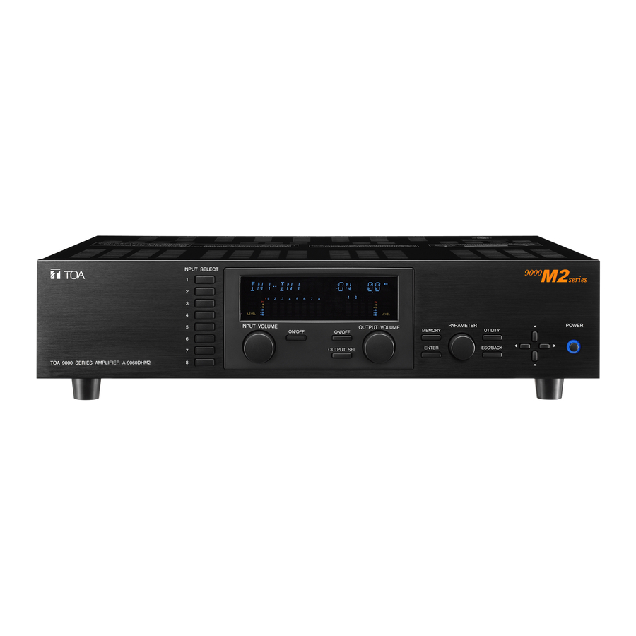
Page 12: 9000M2 Series Amplifier [Front]
7. NOMENCLATURE AND FUNCTIONS 7.1. 9000M2 Series Amplifiers [Front] INPUT SELECT INPUT VOLUME PARAMETER POWER OUTPUT VOLUME ON/OFF ON/OFF MEMORY UTILITY ENTER ESC/BACK OUTPUT SEL 1. Power switch and Power indicator 7. Output channel selection key Press this switch to turn on the power. The power Selects the output channel for which the volume indicator lights. -
Page 13: [Vfd On-Screen Indications]
[VFD on-screen indications] m sec GAIN FREQ KEYLOCK FAULT EMERGENCY FADER FADER TONE GATE –10 –10 LOUD DUCK –20 –20 –30 –30 LEVEL LEVEL COMP DELAY –40 –40 31 32 15. 14-Segment,18-digit alphanumeric display 23. Input level indication Displays the corresponding setting screen or Scale of levels (in dB) for the input meter. - Page 14 28. Output channel selection indicator (red dot) 31. Output level indication Lights when the corresponding output channel is Scale of levels (in dB) for the output meter. selected, and flashes while parameters are being edited. 32. Output meter status indicator Indicates which the output level (LEVEL) or 29.
-
Page 15: [Changing The Indicated Channels On The Level Output Meter]
[Changing the indicated channels on the LEVEL output meter] The output meter indicates the signal levels of only a set of 4 channels: CH 1 – 4 (factory-preset) or CH 5 – 8. When the input or output gain setting screen is displayed, pressing the Up shift key alternately switches the level indication between CH 1 –... -
Page 16: [Rear]
[Rear] • M-9000M2 CTRL REMT VOL1 OUT 1 REMT VOL2 H : Hot C : Cold E : Earth RS-232C OUT 2 • A-9060DHM2, A-9120DHM2 WARNING CTRL DO NOT CONNECT NEGATIVE(–) TERMINALS OUT 1 REMT TOGETHER. VOL1 IN 1 REMT... -
Page 17: Power Cord (2 M Or 6.56 Ft)
40. Preamplifier output 35. RS-232C serial communication port and Power amplifier input terminals Connector for communications with a personal [M-9000M2] computer or control equipment. There are 2 preamplifier output terminals. For unbalanced connection, connect the unit's Hot 36. Functional earth terminal... -
Page 18: Optional Modules
7.2. Optional Modules 7.2.1. D-001T and D-001R (2-Channel Input Modules) The D-001T and D-001R modules are designed for use with the 9000M2 Series amplifiers. Up to 4 modules (8 channels in total) can be inserted into the amplifier. Both modules can handle signals ranging from microphone level (–60 dB) to line level (–10 dB) in 9 input sensitivity levels. -
Page 19: Zp-001T (Zone Paging Module)
7.2.3. ZP-001T (Zone Paging Module) The ZP-001T module is designed for use with the 9000M2 Series amplifiers and functions as an interface to connect the 9000M2 Series amplifiers to an analog PABX, allowing zone paging to be initiated from the PABX. Only one ZP-001T module can be used per 9000M2 Series amplifier. -
Page 20: C-001T (Control I/O Expansion Module)
7.2.4. C-001T (Control I/O Expansion Module) The C-001T module is designed for use with the 9000M2 Series amplifiers and can provide up to 8 channels each of input and output expansion. Since the main unit has 4 fixed inputs and outputs each, the control input and output can be expanded to up to 12 channels each when the C-001T module is used. -
Page 21: Rc-001T (Remote Control Module)
7.2.6. RC-001T (Remote Control Module) The RC-001T is an interface module to connect between the 9000M2 Series amplifier and the ZM-9011, ZM- 9012, ZM-9013, or ZM-9014 Remote Control Panel of data communication type. It allows the control panels to perform paging activation, scene memory change, and input/output volume control. Up to 16 control panels can be connected to the RC-001T. -
Page 22: Optional Accessories
7.3. Optional Accessories 7.3.1. AN-9001 (Ceiling Mount Microphone) The AN-9001 is designed to be mounted in a wall or ceiling with the use of a 1-gang electrical box. It is used in conjunction with the AN-001T Ambient Noise Sensor Input module in the 9000M2 Series system. [Front] [Side] [Rear]... -
Page 23: Zm-9001 (Zone Manager)
7.3.2. ZM-9001 (Zone Manager) The ZM-9001 adds 6 control inputs and can be mounted in a 1-gang electrical box. [Front] [Side] [Rear] E OUT [Bottom] 2. Control buttons [1 – 6] Activate the function assigned to them when pressed. 3. Control output terminal [E, OUT] Connect this terminal to the 9000M2 Series amplifier's REMT VOL terminal. -
Page 24: Zm-9002 (Zone Manager)
7.3.3. ZM-9002 (Zone Manager) The ZM-9002 adds 4 control inputs and 1 volume control, and can be mounted in a 1-gang electrical box. [Front] [Side] [Rear] E OUT [Bottom] 4. Control buttons [1 – 4] Activate the function assigned to them when pressed. 5. -
Page 25: Zm-9003 (Zone Manager)
7.3.4. ZM-9003 (Zone Manager) The ZM-9003 is a remote control switch panel with 4 control selection buttons and 2 control buttons. Connecting it to the 9000M2 Series amplifier's control input terminal permits various controls such as BGM source selection and the sound volume adjustment. It can be mounted in an American standard 2-gang electrical box in a wall. -
Page 26: Zm-9011 (Remote Control Panel)
7.3.5. ZM-9011 (Remote Control Panel) Designed to be connected to the RC-001T, the ZM-9011 is equipped with 4 buttons to perform various controls. The in-use indicators turn on or off synchronizing with the amplifier operation through data communications between the ZM-9011 and the RC-001T. It can be mounted in an American standard 1-gang electrical box. -
Page 27: Zm-9012 (Remote Control Panel)
7.3.6. ZM-9012 (Remote Control Panel) Designed to be connected to the RC-001T, the ZM-9012 is equipped with a volume control knob to perform the volume level setting on the set input or output channel. The indicators show the volume level set by the volume control knob, that is the volume control knob position. It can be mounted in an American standard 1-gang electrical box. -
Page 28: Zm-9013 (Remote Control Panel)
7.3.7. ZM-9013 (Remote Control Panel) Designed to be connected to the RC-001T, the ZM-9013 is equipped with 8 buttons to perform various controls. The in-use indicators turn on or off synchronizing with the amplifier operation through data communications between the ZM-9013 and the RC-001T. It can be mounted in an American standard 2-gang electrical box. -
Page 29: Zm-9014 (Remote Control Panel)
7.3.8. ZM-9014 (Remote Control Panel) Designed to be connected to the RC-001T, the ZM-9014 is equipped with 4 buttons to perform various controls and a volume control knob to perform the volume level setting on the set input or output channel. The indicators show the volume level for a channel set by the volume control knob, that is the volume control knob position. - Page 30 Function buttons and indicators on the ZM-9011, ZM-9013, and ZM-9014 The lighting mode of the operation indicator differs depending on the function assigned to the Function button. When a communication error occurs between these remote control panels and the RC-001T module, the lighting mode differs from that in the normal state regardless of the function assigned to the button.
-
Page 31: Ss-9001 (Speaker Selector)
7.3.9. SS-9001 (Speaker Selector) The SS-9001 selectively distributes each of 2 inputs to the same 4 output zones. 9000 SERIES SPEAKER SELECTOR IN 1 ZONE 1 70V/100V MAX. 240W IN 2 IN 2 70V/100V MAX. 240W ZONE 2 CTRL IN IN 2 ZONE 1 ZONE 2... -
Page 32: Operation Outline
8. OPERATION OUTLINE The unit can be used as a mixer amplifier or a paging amplifier depending on settings. The operation outline in each application is described below. 8.1. Using as a Mixer Amplifier The ideal system for speech reinforcement applications in hotel meeting rooms, churches, and conference rooms and for sound reinforcement applications can be built. -
Page 33: Using As A Paging Amplifier
8.2. Using as a Paging Amplifier Allows input channels to have priority levels and the paging calls using these inputs to interrupt broadcasts being made through mixing inputs. To enable paging calls, paging settings must be performed in addition to the input/output settings. For the paging output destination, group maximum 8 output channels to make up maximum 32 paging groups. -
Page 34: Paging Using The Zp-001T Module
[Operation at normal broadcasts] Normally BGM is broadcast (Input channel 2) in the sales area. When initiating paging with a paging microphone for sales area (Input channel 3), the paging call goes through, causing BGM volume level to decrease. [Operation at emergency broadcasts] When initiating paging with a paging microphone for emergency broadcast (Input channel 1), the paging call goes through to the whole area, causing BGM broadcast and in-store paging announcement currently being made to decrease. - Page 35 [Telephone paging in MANUAL mode] This is a method to directly select each output channel with the telephone key operation. In this mode, if the paging zone number and the output channel number are identical, paging zones can freely be combined with the key operation without the need to perform paging zone settings. 9000M2 series Telephone paging “0123#”...
-
Page 36: Cross Point On/Off Control Using The Remote Controller
8.2.3. Cross point ON/OFF control using the remote controller When the cross point ON/OFF function has been assigned to the buttons on the remote controller, sound source to be output to the output channel can be selected by pressing the button. Two control modes are made available for the cross point ON/OFF function: "EXCLUSIVE"... - Page 37 In such setting on the previous page, the remote controller with address "0" functions as a remote controller that can switch Input 1, 2, or 3 for Output 1. Similarly, the remote controller with address "1" functions a remote controller that can switch Input 1, 2, or 3 for Output 2.
- Page 38 [SIMULTANEOUS MODE] Arbitrary cross points assigned to the buttons on the remote controller can be turned ON or OFF. Arbitrary cross points can be assigned to a single button. This is a convenient function to individually turn ON or OFF the sound source output channel by the remote controller installed at the output destination, which is ideal for selecting and outputting the multiple sound sources by pressing a button on the remote controller at the output destination.
- Page 39 9000M2 series Input channel 1 BGM player Microphone (MIC 1) Input channel 2 Microphone Input channel 3 (MIC 2) No audio output Mixed audio signals of BGM, MIC 1, and MIC 2 OUT 1 OUT 2 Remote controller with address "0" Zone 2 (Output channel 2) Zone 1 (Output channel 1) (When one room is partitioned into two sections)
-
Page 40: Glossary
8.3. Glossary • ANC (Ambient Noise Control) function (AN-001T only) The ANC function automatically adjusts the amplifier's output volume in response to the change in ambient noise level. The output volume changes as the ambient noise level goes above or below the set reference level. •... -
Page 41: Operation
9. OPERATION To operate the unit, you can use the saved Scene settings, or adjust the sound volume and tone or turn the input/output channels on or off through the front key operation or by way of remote control with the default settings as they are. -
Page 42: Changing The Output Parameters
9.1.4. Changing the output parameters Step 1. Press the Output channel selection key to turn on the Output channel selection indicator (red dot) for the output channel for which you want to change volume. Channels to be selected will change each time the Output channel selection key is pressed. The channel name and volume level are displayed on the VFD screen. -
Page 43: Recalling Scene Memory
9.2. Recalling Scene Memory A "Scene" defines the unit of broadcast pattern. Up to 32 patterns can be stored as Scene memory in the Scene memory bank, which can then be recalled. – S C E N E MEMORY Step 1. Press the Memory key to display the Scene memory setting screen. -
Page 44: Making Zone Paging
9.3. Making Zone Paging To make the zone paging broadcast setting easier, clarify the following points before performing the setting. · Input (source) to access paging broadcast · Paging trigger and paging destination zones · Equipment or function to be interlocked with paging Paging settings are described below. - Page 45 [Paging initiation by the ZM-9011, ZM-9012, ZM-9013, or ZM-9014 operation] When assigning the paging activation function to the button on the remote control panel, pressing the function- assigned button causes the paging to initiate. Example: ZM-9011 Step 1. Press the button on the remote control panel. The corresponding indicator lights.
-
Page 46: Zone Paging Using The Zp-001T Module
9.3.2. Zone paging using the ZP-001T module This section describes the method of initiating zone paging from a PABX (extension telephone) using the ZP- 001T Zone Paging Module. The following 2 operation modes are available for the ZP-001T: Paging port mode and Ring signal mode. - Page 47 [Ring signal mode] Step 1. Make a call from the extension telephone to the ZP-001T module. After a calling tone sounds twice, the ZP-001T receives the call and a callback tone is heard from the handset. Step 2. Select the output channel. The output selection method differs as follows depending on the paging method setting made on the VFD screen.
-
Page 48: Releasing Key Lock
9.4. Releasing Key Lock The key lock function prevents the front-mounted keys or knobs from being tampered. (Refer to p. 88 "Key Lock Function Setting.") You can temporarily operate the locked keys by entering a password to unlock them. Operation after password entry differs depending on the locked keys. -
Page 49: Operation Example
9.5. Operation Example The operation procedure is described here using an example to change the output parameters after recalling the Scene memory when the output operation key is locked. – S C E N E Step 1. Press the Memory key to display the Scene memory setting MEMORY screen. -
Page 50: Settings
10. SETTINGS Use the VFD screen, keys, and Parameter setting knob on the unit's front panel to make settings. Settings are categorized into two types of items: Items recommended to be set before operation (input settings, audio output settings, and UTILITY settings), and items that limit the front panel's key and knob operation (keylock settings, which are a part of UTILITY settings). -
Page 51: Utility Setting Configuration
10.1.3. Utility setting configuration Perform stereo link settings for the input and output channels, function assignment to the control input and output terminals, keylock settings, and password setting. Press the Utility key at the normal use state screen to proceed to the setting screen. Each individual item setting UTILITY Refer to p. -
Page 52: Input Setting Flow Chart
10.2. Input Setting Flow Chart Setting items differ depending on the modules used for input channels. Refer to this page when the D-001T or D-001R is used, p. 54 when the ZP-001T is used, and p. 55 when the AN-001T is used. 10.2.1. - Page 53 From the previous page Only when Paging is set to (p.59-A12) (p.59-A13) P R I O R I T Y D U C K E R - D E P T H O F F : 1, 2, 3 : OFF, -50, -40, -30, -20, -10, 0 (dB) Only when Paging is set to (p.60-A15) (p.60-A18)
-
Page 54: Input Setting Flow Chart For The Channel On Which The Zp-001T Is Used
10.2.2. Input setting flow chart for the channel on which the ZP-001T is used To/from lowermost screen The screen display examples may differ from actual displays. The on-screen indications shown in blue are variable parameters (p.56-A1) INPUT SELECT INPUT SELECT by key operation. -
Page 55: Input Setting Flow Chart For The Channel On Which The An-001T Is Used
10.2.3. Setting flow chart for the channel on which the AN-001T is used The screen display examples may differ from actual displays. To/from lowermost screen The on-screen indications shown in blue are variable parameters INPUT SELECT INPUT SELECT by key operation. Normal use state : Cycles meter display (FADER /LEVEL) below the setting screen each time pressed. -
Page 56: Input Setting Items
10.2.4. Input setting items Unless otherwise specified, use the Parameter setting knob for each parameter selection. (A1) Input gain setting I N 1 - I N 1 : O N 0. 0 Select the input channel using the Input channel selection key. Confirm the selection by setting the Input channel ON/OFF key to ON. - Page 57 (A5) Phantom power ON/OFF setting (when the D-001T/R is used) I N 1 - P H A N T O M O F F Set the Phantom power to ON or OFF. Notes • When the module is the D-001R, this function can be set to ON but cannot be output. •...
- Page 58 (A9) EQ ON/OFF, Band number, Gain, Q, and Center frequency settings (when the D-001T/R is used) 0 d B Q 1. 5 3 1. 5 Band number Center frequency Gain The indications on the right of "EQ" turn on and off as the Parameter setting knob is rotated. When the indication is displayed, EQ is ON and a band number, gain, Q, and center frequency are displayed in this order from left to right.
- Page 59 • DEPTH = 5 (Speech leveler) Makes paging calls easier to hear by equalizing the difference in speech signal volume that may result from individual differences in speaker voice volumes or variations in speaker-to-microphone distances. This level 5 is more effective than level 4. Since the volume is extensively corrected, the feedback margin narrows, making it liable to occurrences of feedback.
- Page 60 (A15) Trigger setting (A15) Trigger setting (for the channel on which the module (for the channel on which the ZP-001T other than the ZP-001T is used) is used) P A G I N G T R I G P A G I N G T R I G C - I N Set the trigger to initiate paging.
- Page 61 (A20) Remote controller connection terminal or ID setting I D = -> N O N E When the remote controller to initiate paging is the ZM-9001 or ZM-9002, set its connected control input terminal on the amplifier's rear (REMT VOL1 or REMT VOL2 terminal: RMT1 or REMT2 on the VFD). When the ZM-9011, ZM-9013, or ZM-9014 is used, designate its unit ID number.
- Page 62 (A23) Output assignment and level settings (when the D-001T/R is not used and the paging is set to OFF) I N 1 -> O U T 1 Set which output channel in what level an audio source at the currently selected input channel should be output to.
- Page 63 (A28) Paging method setting P A G I N G : M A N U A L Selects the paging method from MANUAL, AUTO, and GROUP as follows: MANUAL: Directly select the OUTPUT for paging. AUTO: One paging group can be set. ZONEGROUP: Up to 8 paging groups can be set.
- Page 64 (A34) Input channel name setting A N C 1 - - - - - - - - - The flashing portion is the cursor position for entering channel name characters. Select a character from the alphanumeric character list by rotating the Parameter setting knob, then move the cursor with the Right shift key.
- Page 65 (A39) Monitor ON/OFF setting (when the AN-001T is used and ANC operation is set to ACTIVE) M O N I T O R O U T - O F F Set to ON or OFF the monitor function that permits the ambient noise input signal to be output. Setting Range ON, OFF (default) •...
- Page 66 (A44) Gain ratio setting (when the AN-001T is used and ANC operation is set to ACTIVE) G A I N , R A T I O 3 : 3 Set the degree of change in the output sound level to that in ambient noise level, which is displayed as the ratio "ambient noise level : output level."...
-
Page 67: Output Setting Flow Chart
10.3. Output Setting Flow Chart The screen display examples may differ from actual displays. To/from lowermost screen The on-screen indications shown in blue are variable parameters (p.68-B1) OUTPUT SEL by key operation. Normal use state (p.68-B2) O-ON/OFF The symbols in the figure represent the following key operation. 0 1 - S C E N E 1 OUT 1 - O U T 1 O F F... -
Page 68: Output Setting Items
10.3.1. Output setting items Unless otherwise specified, use the Parameter setting knob for each parameter selection. (B1) Output gain setting OUT 1 - O U T 1 : - 2 0. 0 Select the output channel using the Output channel selection key. Confirm the selection by setting the Output channel ON/OFF key to ON. - Page 69 (B5) Speaker parameter presetting E Q -> A L L F L A T Optimum equalization can be automatically set depending on the type of speaker to be used. Speaker models (with their parameters) cannot be selected until written into the amplifier using the separate PC software.
- Page 70 (B6) EQ ON/OFF, Band number, Gain, Q, and Center frequency settings d B Q 1. 5 3 1. 5 Band number Center frequency Gain The indications on the right of "EQ" turn on and off as the Parameter setting knob is rotated. When the indication is displayed, EQ is ON and a band number, gain, Q, and center frequency are displayed in this order from left to right.
- Page 71 (B8) Compressor setting C O M P R E S S O R - O F F Setting Range OFF (default), 1, 2, 3, 4, 5 Use the compressor to prevent power amplifier overload or to produce more easily heard sound by averaging the audio level.
- Page 72 (Only when the delay function is set to ON) (B10) Delay time setting D E L A Y - O N T I M E 0. 0 Set the delay time. Setting Range 0 – 40 ms (default: 0), 1 ms steps Note Maximum 40 ms total of time for Output channels 1 and 2.
-
Page 73: Utility Setting Flow Chart
10.4. UTILITY Setting Flow Chart To/from lowermost screen The screen display examples may differ from actual displays. The on-screen indications shown in blue are variable parameters (p.76-C1) UTILITY by key operation. Normal use state STEREO LINK The symbols in the figure represent the following key operation. 0 1 - S C E N E 1 S T E R E O L I N K S T E R E O L I N K... - Page 74 From the previous page (p.80-C24) (p.80-C24) K E Y L O C K K E Y L O C K U N L O C K E D K E Y L O C K L O C K E D (In KEYLOCK state) Front panel's KEYLOCK indication flashes if any...
-
Page 75: Control Input Terminal's Function Settings
10.4.1. Control input terminal's function settings (p.76-C3) (p.83-C43) P.71 C - I N -> N O N E C - I N 0 1 -> N O N E : 01 to 12 (p.83-C44) (p.83-C45) C - I N 0 1 -> L O A D S C E N E C - I N 0 1 - L O A D S C E N E : 01 to 32... -
Page 76: Utility Setting Items
10.4.3. Utility setting items Unless otherwise specified, use the Parameter setting knob for each parameter selection. (C1) Stereo link setting S T E R E O L I N K O U T 1 = 2 Set a paired input or output channel as stereo input or stereo output so that both channels can be synchronously operated. - Page 77 (C5) Control input terminal function display C - I N I N F N O N E Displays the function assigned to the control input terminal. The screen indications represent the following functions: • NONE: No function is assigned. • PG TRIG: Paging activation •...
- Page 78 (C10) Control output terminal function display C - O U T I N F N O N E Displays the function assigned to the control output terminal. The screen indications represent the following functions: • NONE: No function is assigned. •...
- Page 79 (C15) Remote-controlled channel setting (when the remote controller type is set to VOLUME or ZM-9002) R E M O T E 1 -> O U T P U T 1 Select the input or output channel of which volume you want to remotely control by using the control input terminals on the rear panel or ZM-9002's volume control.
- Page 80 (C20) Monitor switching control input terminal setting (When the ANC monitor switching is set to ON) M O N S E L E C T -> C - I N 0 1 Select the control input terminal to switch the ANC inputs* to be monitored. Selecting the terminal overwrites the previously set function on it if there is.
- Page 81 (C26) All-key lock ON/OFF K E Y L O C K A L L O F F Selecting ON locks all keys located on the front panel. If ON/OFF settings differ from key to key, the [- - -] indication is displayed when this screen appears. (C27) Input key lock ON/OFF K E Y L O C K I N P U T...
- Page 82 (C33) Password setting (C36) Password deletion S E T P A S S W O R D C L E A R P A S S W O R D Sets or deletes the password. To set the password, press the Enter key at the password setting screen to proceed the setting. To delete the set password, press the Enter key at the password deletion screen, and the confirmation screen is displayed.
- Page 83 (C40) Slot number selection and 900 series module classification setting M O D U L E S L O T = D - 0 0 1 T Setting Range Slot Number 1 – 8 (default: 1) Module Classification OTHERS (default), B-01, B-11, B-21, B-41, E-03, E-04, E-05, E-06, E-07, L-01, L-11, L-41, M-01, M-03, M-11, M-21, M-41, M-51, M-61, S-01, S-02, S-04, S-20S, T-01, T-02, T-12, U-01, U-03, U-11, U-12, U-13, U-14, U-21, U-43, U-61, V-01, ML-11T,...
- Page 84 [When the function is set to VOLUP or VOLDOWN] (C46) (C47) (When the control input function is set to VOLUP) (When the control input function is set to VOLDOWN) C - I N 0 1 -> V O L U P C - I N 0 1 ->...
- Page 85 [When the function is set to CH MUTE] (C54) (When the control input function is set to CH MUTE) C - I N 0 1 -> C H M U T E Assign the function that mutes the input or output channel to the control input. Closing the control input terminal mutes the set channel.
- Page 86 (When the interlock output control is set to ON) (C60) Interlock output terminal setting C - I N 0 1 - C - O U T This screen is displayed only when the interlock output control setting is set to ON. Set the control output terminal which is closed in synchronization with the control input of the set number.
- Page 87 [When the function is set to SCENE] (C66) (When the control output function is set to SCENE) C - O U T 0 1 -> L D S C E N E Provides a Level output when a Scene memory is recalled. Assigning a function to this terminal overwrites the previously set function on it if there is.
-
Page 88: Key Lock Function Setting
10.5. Key Lock Function Setting The key lock function prevents equipment malfunctions by disabling operation of each key. 10.5.1. Keys that can be locked INPUT SELECT POWER INPUT VOLUME OUTPUT VOLUME PARAMETER ON/OFF ON/OFF MEMORY UTILITY ENTER ESC/BACK OUTPUT SEL INPUT OUTPUT UTIL... -
Page 89: Password Setting
10.5.2. Password setting When using a password, set the password before performing lock setting for each key. Step 1. Press the Utility key. – S C E N E The Utility setting screen is displayed. UTILITY S T E R E O L I N K Step 2. -
Page 90: Key Lock Setting Operation
10.5.3. Key lock setting operation – S C E N E Step 1. Press the Utility key. The Utility setting screen is displayed. UTILITY S T E R E O L I N K Step 2. Press the Down shift key until the keylock screen is displayed. -
Page 91: Memory Setting Flow Chart
10.6. MEMORY Setting Flow Chart The screen display examples may differ from actual displays. The on-screen indications shown in blue are variable parameters MEMORY by key operation. Normal use state (p.92-D1) (p.92-D2) The symbols in the figure represent the following key operation. 0 1 - S C E N E 1 S C E N E S E T T I N G... -
Page 92: Scene Memory Setting Items
10.6.1. Scene memory setting items Unless otherwise specified, use the Parameter setting knob for each parameter selection. (D1) Scene memory setting S C E N E S E T T I N G L O A D Set the Scene memory function. Setting Range LOAD (default), SAVE, ERASE, P-ON •... - Page 93 (D4) Scene memory erasure (when ERASE is set) E R A S E <- S C E N E 1 Erase the saved Scene memory. Setting Range 01 – 32 (default: 01) Pressing the Enter key erases the Scene memory in the designated memory bank number. To cancel erasure execution, press the Escape/Back key.
-
Page 94: How To Store Or Erase Scene Memory
11. HOW TO STORE OR ERASE SCENE MEMORY A "Scene" defines the unit of broadcast pattern. Up to 32 patterns can be stored as Scene memory in the Scene memory bank, which can then be recalled. 11.1. Recalling Scene Memory –... -
Page 95: Storing Scene Memory
11.2. Storing Scene Memory – S C E N E Step 1. Hold down the Memory key. The Scene memory setting screen is displayed. MEMORY S C E N E S E T T I N G L O A D Step 2. -
Page 96: Erasing Scene Memory
11.3. Erasing Scene Memory – S C E N E Step 1. Hold down the Memory key. The Scene memory setting screen is displayed. MEMORY S C E N E S E T T I N G L O A D PARAMETER Step 2. -
Page 97: Setting The Scene Memory To Be Recalled At Power-On
11.4. Setting the Scene Memory to be Recalled at Power-On – S C E N E Step 1. Hold down the Memory key. The Scene memory setting screen is displayed. MEMORY S C E N E S E T T I N G L O A D Step 2. -
Page 98: Restoring Factory Default Setting
12. RESTORING FACTORY DEFAULT SETTING Follow the procedures below to return all settings to default values while using the unit in the matrix mode. Details of the default values are shown on the next page, "Default Setting Table." – S C E N E Step 1. -
Page 99: Default Setting Table
12.1. Default Setting Table 12.1.1. Input settings Setting Item Default Input channel Selection Channel Control Channel Gain 0.0 dB Channel Name (IN1 – 8) Paging ON/OFF [Paging: ON] Paging Input Channel Trigger D-001T: VOX ZP-001T: ZP Paging Zone Output Channel OUT1 [Settings when the D-001T/R is used] Phantom Power ON/OFF... -
Page 100: Output Settings
[Settings when the AN-001T is used] ANC Operation ON/OFF BYPASS Input Sensitivity –10 dB Phantom Power ANC-Activated Output OUT1 Monitor ON/OFF Monitor Output Channel OUT1 (When the monitor ON/OFF setting is ON) Lowest Output Level –6 dB Highest Output Level 0 dB Sampling Time 20 sec... -
Page 101: Utility Settings
12.1.3. Utility settings Setting Item Default Stereo Link No channel is stereo-linked. NOM Attenuation Control Input Terminal Number Control Input Terminal Function Display NONE Control Input Terminal Status Display _ _ _ _ _ _ _ _ _ _ _ _ (All terminals are open.) Control Output Terminal Number Control Output Terminal Function Display NONE... - Page 102 [Control input function setting] Control Input Function NONE • Control input function: LOADSCENE Scene Memory Bank Number • Control input function: VOLUP Input/Output Channel Number Volume Increasing Level 0.5 dB • Control input function: VOLDOWN Input/Output Channel Number Volume Decreasing Level 0.5 dB •...
-
Page 103: Scene Memory Settings
12.1.4. Scene memory settings Setting Item Default Scene Memory Recall Scene Memory Setting SAVE [Scene memory: SAVE] Memory Bank Number Scene Memory Name SCENE1 [Scene memory: ERASE] Memory Bank Number [Scene memory: P-ON] LASTSCENE Scene Memory Bank Number To Be Recalled at Power-On... -
Page 104: Module Installation
13. MODULE INSTALLATION Important Be sure to detach the power cord when inserting or removing any module. 13.1. Module Combination The unit is designed to provide an up to 8-input/8-output configuration in combination with its optional modules. Inputs are configured by only using the modules. (No input terminals are located on the rear panel.) For outputs, 2 output channels are provided on the rear panel and can be expanded by adding modules. - Page 105 Step 2. Insert the AN-001T module into the slots in Slot 1 order without leaving slots open in between. D-001T/R AN-001T Notes is mounted • Up to 8 audio inputs including AN-001T's inputs can be used per amplifier. (Example when no D-001T/R is mounted) •...
-
Page 106: Module Installation Examples
13.4. Module Installation Examples [Example of audio 8 IN/8 OUT and control 12 IN/12 OUT configuration] Slot No. C-001T T-001T T-001T T-001T D-001T/R D-001T/R D-001T/R D-001T/R Control Audio Audio Audio Audio Audio Audio Audio 8 inputs 2 outputs 2 outputs 2 outputs 2 inputs 2 inputs... -
Page 107: Connections
14. CONNECTIONS 14.1. Control I/O Terminal Connections CTRL REMT VOL1 REMT VOL2 Control-I/O connection terminal [Remote volume control terminals 1, 2 (REMT VOL 1, REMT VOL 2)] Volume of the input or output channels can be remotely adjusted by connecting a variable resistor or variable DC power supply unit. -
Page 108: When The Zm-9001 Or Zm-9002 Is Connected
14.1.2. When the ZM-9001 or ZM-9002 is connected Note One ZM-9001 or one ZM-9002 can be connected to each of the REMT VOL1 and 2 terminals. 14.1.3. When the ZM-9003 is connected Output terminal Nos. 1 – 4 of the ZM-9003 are internally connected to the interlocking switches and Nos. 5 and 6 to the momentary switches. -
Page 109: Operation By Control Input
14.1.5. Operation by control input [Pulse trigger] Use this method to activate operations for which no definite end can be defined, such as "VOL UP/DOWN" (Volume Up/Down), "LOADSCENE" (Scene memory recall), and "CH ON." Minimum pulse width is 100 ms. Over 100 ms High State changes at the falling edge. -
Page 110: Speaker Output Terminal Connections
14.2. Speaker Output Terminal Connections 14.2.1. A-9060SM2 and A-9120SM2 The A-9060SM2 and A-9120SM2 are equipped with speaker output terminals of 70 V, 25 V, and 8 Ω transformer output, and 4 Ω direct output. [Transformer output terminal connection] Connect the supplied jumper wire* between 4 Ω (DIRECT) and TRANS IN terminals as shown below. Then, connect speakers to COM terminal and 70 V, 25 V, or 8 Ω... -
Page 111: A-9060Dhm2 And A-9120Dhm2
14.2.2. A-9060DHM2 and A-9120DHM2 The speaker output terminals of the A-9060DHM2 and A-9120DHM2 are designed for 70 V line applications. Both CH 1 and CH 2 outputs are provided on the 4P terminal block. Connect the speaker cables to each positive terminal (+) and negative terminal (–) individually. 70 V OUT 1 70 V... -
Page 112: C-001T Module Connections
14.3. C-001T Module Connections 14.3.1. Control input terminal For operation by means of the control (Open voltage: 3.3 V, Max. 1 mA) inputs, refer to p. 109 "Operation by control input." Contact closures Open collectors, etc. 14.3.2. Control output terminal LEDs, Relays, etc. -
Page 113: Connecting The Ss-9001
14.3.4. Connecting the SS-9001 The control input terminals of SS-9001 are polarized non-voltage contact inputs. When the control output terminals of C-001T are closed, the corresponding internal relays of the SS-9001 are activated. Make necessary connections depending on applications. -
Page 114: Rc-001T Module Connection
14.4. RC-001T Module Connection 14.4.1. Connection method To connect the RC-001T Remote Control Module to the Remote control panels such as ZM-9011, ZM-9012, ZM-9013, or ZM-9014, connect the same DATA BUS terminals and the same 24 V DC terminals of the both units. -
Page 115: Cable Distance
14.4.2. Cable distance Cable distance between the RC-001T and Remote control panels (ZM-9011/9012/9013/9014), and the number of connected Remote control panels differ depending on the connection method as shown below. [Star connection configuration] The maximum cable distance between the RC-001T and each Remote control panel is 800 m (875 yd) in total. Example: Up to 16 panels can be connected when the total cable distance is within 800 m (875 yd). - Page 116 [Daisy-chain connection configuration] The number of connected Remote control panels differs depending on the cable distance. When 16 panels are connected, the maximum cable distance for each LINK A and LINK B is 200 m (220 yd). Example 1: When each cable for LINK A and LINK B is extended up to 200 m or 220 yd (400 m or 440 yd in total), 16 panels can be connected irrespective of the distance between RC-001T and panels, and between panels.
- Page 117 Example 3: When each cable for LINK A and LINK B is extended up to 400 m or 440 yd (800 m or 875 yd in total), 12 panels can be connected irrespective of the distance between RC-001T and panels, and between panels.
-
Page 118: Rs-232C Connector Connection
14.5. RS-232C Connector Connection Use the straight cable when connecting a PC to the unit's RS-232C connector (9P, female). 9000M2 Series amplifier RS-232C connection (Male) (Female) Straight cable 14.6. AN-001T and AN-9001 Connections The AN-001T and AN-9001 are connected as illustrated below and used to control the speaker sound volume in a room or such closed space. -
Page 119: Power Source Connections To The Ss-9001
14.7. Power Source Connections to the SS-9001 14.7.1. When using a 24 V DC power source Connect a 24V DC power source to the SS-9001's DC input terminal pins. Notes • The DC power supply unit should be capable of supplying 200 mA or more. -
Page 120: Removable Terminal Plug Connection
14.8. Removable Terminal Plug Connection Be sure to use the supplied removable terminal plugs for connections to the removable terminal blocks. Cautions • Be sure to use shielded cables for audio signal lines and for the ZM-9001/9002/9011/9012/9013/9014 control lines. • Avoid soldering stranded or shielded cable, as contact resistance may increase when the cable is tightened and the solder is crushed, possibly resulting in an excessive rise in joint temperatures. -
Page 121: Rack Mounting Bracket Attachment
15. RACK MOUNTING BRACKET ATTACHMENT Use the supplied rack mounting bracket when mounting the unit in an equipment rack. Step 1. Remove four M4 x 8 screws on the sides. The removed screws are no longer used. Step 2. Attach the rack mounting bracket to the unit using the supplied four M4 x 16 bracket mounting screws. Bracket maunting screw M4 x 16 (supplied) IN P Rack mounting bracket... -
Page 122: An-9001 Installation
16. AN-9001 INSTALLATION Step 1. Install a 1-gang electrical box in a wall or ceiling. Step 2. Mount the AN-9001's Main unit to the installed electrical box. Use the 2 screws (No.6-32UNC x 30) supplied with the AN-9001. Note The AN-9001 comes with 2 types of machine screws: No.6-32UNC x 30 (unified threads) and M4 x 30 (metric threads). -
Page 123: Dimensional Diagrams
17. DIMENSIONAL DIAGRAMS 17.1. AN-9001 Unit: mm (in) 31 (1.22) [Front] 37 (1.46) [Side] 38 (1.5) 42 (1.65) [Bottom] 1-gang Electrical Box (not supplied) 46 – 50 (1.81 – 1.97) [Figure when mounted] [Dimensions of mounting opening] 70 (2.76) [Front view of Main unit]... -
Page 124: Zm-9001
17.2. ZM-9001 Unit: mm (in) 45 (1.77) 72 (2.83) 33 (1.3) 37 (1.46) 32.6 (1.28) [Front View without panel] [Front] [Side] (0.24) 1-gang electrical box (not supplied) 38 (1.5) 42 (1.65) 46 – 50 (1.81 – 1.97) [Bottom] [Figure when mounted] [Dimensions of mounting opening] 17.3. -
Page 125: Zm-9003
17.4. ZM-9003 Unit: mm (in) [Front] [Side] [Rear] 120 (4.72) 66 (2.6) 53.3 (2.1) (0.28) (1.57) [Bottom] [Figure when mounted] 88 (3.46) 2-gang electrical box (American type, not supplied) [Front view without panel] 79 (3.11) 46 (1.81) 66 (2.6) 99 (3.9) -
Page 126: Zm-9011
17.5. ZM-9011 Unit: mm (in) 72 (2.83) 49.5 (1.95) 33 (1.3) 40.5 (1.59) 32.6 (1.28) [Front View without panel] [Front] [Side] (0.24) 1-gang electrical box (not supplied) 38 (1.5) 46 – 50 (1.81 – 1.97) 42 (1.65) [Bottom] [Figure when mounted] [Dimensions of mounting opening] 17.6. -
Page 127: Zm-9013
17.7. ZM-9013 Unit: mm (in) [Front] [Side] [Rear] 120 (4.72) 66 (2.6) 50.5 (1.99) 40.5 (0.28) (1.59) [Bottom] 84.5 (3.33) [Figure when mounted] 88 (3.46) 2-gang electrical box (American type, not supplied) [Front view without panel] 79 (3.11) 46 (1.81) 66 (2.6) 99 (3.9) -
Page 128: Zm-9014
17.8. ZM-9014 Unit: mm (in) [Front] [Side] [Rear] 120 (4.72) 66 (2.6) 58.5 (2.3) 40.5 (0.28) (1.59) [Bottom] 84.5 (3.33) [Figure when mounted] 88 (3.46) 2-gang electrical box (American type, not supplied) [Front view without panel] 79 (3.11) 46 (1.81) 66 (2.6) 99 (3.9) -
Page 129: Ss-9001
17.9. SS-9001 Unit: mm (in) 9000 SERIES SPEAKER SELECTOR IN 1 ZONE 1 70V/100V MAX. 240W IN 2 IN 2 70V/100V MAX. 240W ZONE 2 CTRL IN IN 2 ZONE 1 ZONE 2 ZONE 3 ZONE 3 ZONE 4 IN 2 DC IN 120mA ZONE 4... -
Page 130: Outline Of The Attached Software
Refer to the Setting software manual on how to use the Setting software. The latest firmware version of the 9000M2 series is made available on the TOA product data download site (http://www.toa-products.com/international/). The communication speed is fixed regardless of the setting... -
Page 131: Error Indications
There may be overload or excessive signal input. DC PROTECT (OUTPUT #No.) Check input and output signal levels and gain settings, then adjust them as necessary. If the indicator remains lit, consult your TOA dealer. The unit is heated to a high temperature. -
Page 132: Troubleshooting
20. TROUBLESHOOTING Symptom Possible Cause Remedy Noise generated. Module mounting screw not If this screw is loose, noise may be produced. securely tightened. Ensure that the screw is tightened. Excessive noise. Incorrect module input The unit is designed to digitize audio signals sensitivity setting. -
Page 133: Block Diagram
–VCC MAIN_TRANS CONTROL INPUT +24 V ANALOG –24 V AC IN +6 V DSP/AD/DA CONTROL OUTPUT +3.3 VBU CPU SUB_TRANS (EXCEPT M-9000M2) MEMORY UTILITY ON/OFF ON/OFF –30 V AC5 V AC5 V OUTPUT SEL 232RXD RS232 INPUT SELECT INPUT VOLUME... -
Page 134: Signal Flow Diagram
SHARE 10-Band EQ resources INPUT +24 V –10 SENSITIVITY Phantom INPUT –20 –60, –54, –48, –42, –36, –30, –24, –18, –10 dBV Power –30 VOLUME M-9000M2 –40 ON/OFF LEVEL METER T-001T DUAL LINE OUTPUT with DSP 10BAND INPUT-1 P-EQ –10 COMP TONE LOUDNESS OUTPUT –20... -
Page 135: Level Diagram
(200 mV) –20 Reference Level (100 mV) 10 dB 10 dB 10 dB –30 –14 dBV (200 mV) M-9000M2 –10 dB ATT MIXOUT NE5532 OUT 1 (0 dB Gain) H: Hot (+14 dB Gain) SLOT 0 dBFS = 1 V... -
Page 136: Compression Characteristics Diagram
24. COMPRESSION CHARACTERISTICS DIAGRAM The diagram below shows the compression characteristics on p. 58-A10 71-B8. COMPRESSOR –10 –20 –30 –40 DEPTH = 1 & 2 DEPTH = 3 –50 DEPTH = 4 DEPTH = 5 –60 –70 –80 –90 –100 –96 –91 –86... -
Page 137: Speaker Preset Parameter List
25. SPEAKER PRESET PARAMETER LIST Described here are parameters that can be used for the speaker parameter presetting screen (p. 67 and 69). Depending on the speaker models such as F-1000, F-1300, F-2000, and SR-T5, "ALL FLAT" parameter is recommended to be set as general use. However, set EQ parameters according to the installation environment. - Page 138 H-3 LOWCUT* GAIN (dB) FREQ (Hz) GAIN (dB) FREQ (Hz) EQ 01 0.707 0.707 EQ 02 2.871 2.871 EQ 03 –8 2.871 –8 2.871 EQ 04 2.871 2.871 EQ 05 +1.5 0.305 +1.5 0.305 EQ 06 EQ 07 Settable EQ bands Settable EQ bands EQ 08 in the EQ setting screen...
- Page 139 HX-5* HX-5 LOWCUT* GAIN (dB) FREQ (Hz) GAIN (dB) FREQ (Hz) EQ 01 2.053 1.307 EQ 02 1.414 –3 EQ 03 –3 –4 2500 2.997 EQ 04 –4 2500 2.997 5000 0.305 EQ 05 5000 0.305 EQ 06 EQ 07 Settable EQ bands Settable EQ bands EQ 08...
- Page 140 FB-2852 GAIN (dB) FREQ (Hz) EQ 01 0.707 EQ 02 0.707 EQ 03 1.985 EQ 04 –3 3.134 EQ 05 –5.5 3.134 EQ 06 –2 4.318 EQ 07 –4 1.7 k 0.667 EQ 08 7.3 k 0.49 EQ 09 20 k 0.707 EQ 10 Settable EQ band in the EQ setting screen...
- Page 141 SR-H3S GAIN (dB) FREQ (Hz) EQ 01 EQ 02 EQ 03 –8 EQ 04 –7 EQ 05 EQ 06 EQ 07 Settable EQ bands EQ 08 in the EQ setting screen EQ 09 EQ 10 SR-H3L GAIN (dB) FREQ (Hz) EQ 01 EQ 02 EQ 03...
- Page 142 HS-1200 HS-1500 GAIN (dB) FREQ (Hz) GAIN (dB) FREQ (Hz) EQ 01 1.432 EQ 01 1.274 EQ 02 –5 1.414 EQ 02 –5 2.145 EQ 03 –4 1600 5.764 EQ 03 –4 1300 2.871 EQ 04 –3 2100 5.764 EQ 04 –3 2100 2.871...
-
Page 143: Specifications
10 bands, Frequency: 20 Hz – 20 kHz, 31 steps, Variable range: ±12 dB, Q: 0.3 – 5 Speaker Equalizer 15 (compatible with TOA speakers only) High-pass Filter –12 dB/oct, Variable frequency range: 20 – 400 Hz, 14 steps Low-pass Filter –12 dB/oct, Variable frequency range: 4 –... - Page 144 • Accessories Power cord (2 m or 6.56 ft) ........1 Rack mounting bracket ........2 Bracket mounting screw (M4 x 16) ....... 4 Blank panel ............7 Blank panel mounting screw (M3 x 8) ....14 Removable terminal plug (3 pins) ......2 Removable terminal plug (14 pins) ......
-
Page 145: A-9060Dhm2, A-9120Dhm2
10 bands, Frequency: 20 Hz – 20 kHz, 31 steps, Variable range: ±12 dB, Q: 0.3 – 5 Speaker Equalizer 15 (compatible with TOA speakers only) High-pass Filter –12 dB/oct, Variable frequency range: 20 – 400 Hz, 14 steps Low-pass Filter –12 dB/oct, Variable frequency range: 4 –... -
Page 146: Bracket Mounting Screw (M4 X 16)
0 dB = 1 V Allowing it to be controlled by a control system such as AMX and Crestron through RS-232C port. Notes • The design and specifications are subject to change without notice for improvement. • AMX is a trademark of AMX Corporation. •... -
Page 147: A-9060Sm2, A-9120Sm2
10 bands, Frequency: 20 Hz – 20 kHz, 31 steps, Variable range: ±12 dB, Q: 0.3 – 5 Speaker Equalizer 15 (compatible with TOA speakers only) High-pass Filter –12 dB/oct, Variable frequency range: 20 – 400 Hz, 14 steps Low-pass Filter –12 dB/oct, Variable frequency range: 4 –... - Page 148 Operating Temperature –10 to +40°C (14 – 104°F) Operating Humidity 35% to 80% RH (no condensation) Finish Panel: Aluminum, hair-line, black Case: Surface-treated steel plate, black, paint Dimensions 420 (w) x 107.6 (h) x 355 (d) mm (16.54" x 4.24" x 13.98") Weight 11 kg (24.25 lb) 13 kg (28.66 lb)
-
Page 149: A-9240Shm2
10 bands, Frequency: 20 Hz – 20 kHz, 31 steps, Variable range: ±12 dB, Q: 0.3 – 5 Speaker Equalizer 15 (compatible with TOA speakers only) High-pass Filter –12 dB/oct, Variable frequency range: 20 – 400 Hz, 14 steps Low-pass Filter –12 dB/oct, Variable frequency range: 4 –... - Page 150 0 dB = 1 V Allowing it to be controlled by a control system such as AMX and Crestron through RS-232C port. Notes • The design and specifications are subject to change without notice for improvement. • AMX is a trademark of AMX Corporation. •...
-
Page 151: Optional Modules
26.5. Optional Modules 26.5.1. D-001T Power Source +24 V DC, –24 V DC, +6 V DC Current Consumption 20 mA (at +24 V DC), 20 mA (at –24 V DC), 60 mA (at +6 V DC) Input 2 channels, 3 kΩ (when the phantom power is ON) / 10 kΩ (phantom power is OFF), electronically-balanced, removable terminal block (3 pins) Input Sensitivity –60, –54, –48, –42, –36, –30, –24, –18, –10 dB* (selectable) -
Page 152: D-001R
26.5.2. D-001R Power Source +24 V DC, –24 V DC, +6 V DC Current Consumption 20 mA (at +24 V DC), 20 mA (at –24 V DC), 60 mA (at +6 V DC) Input 2 channels, 2 RCA jacks/ch mixed, 10 kΩ, unbalanced, RCA jack Input Sensitivity –60, –54, –48, –42, –36, –30, –24, –18, –10 dB* (selectable) Frequency Response... -
Page 153: T-001T
10 bands, Frequency: 20 Hz – 20 kHz, 31 steps, Variable range: ±12 dB, Q: 0.3 – 5 Speaker Equalizer 15 (compatible with TOA speakers only) High-pass Filter –12 dB/oct, Variable frequency range: 20 – 400 Hz, 14 steps Low-pass Filter –12 dB/oct, Variable frequency range: 4 –... -
Page 154: C-001T
26.5.4. C-001T Power Source 6 V DC Current Consumption 15 mA Control Input 8 channels, open voltage: 3.3 V DC, short-circuit: under 1 mA, removable terminal block (9 pins) Control Output 8 channels, open collector output, withstand voltage: 27 V DC, control current: max. -
Page 155: An-001T
26.5.6. AN-001T Power Source +24 V DC, –24 V DC, +6 V DC Current Consumption 20 mA (at +24 V DC), 20 mA (at –24 V DC), 60 mA (at +6 V DC) Input Sensor input (Ambient noise sensor microphone input): 2 channels, 3 kΩ... -
Page 156: Optional Accessories
26.6. Optional Accessories 26.6.1. AN-9001 Type Electret condenser microphone Phantom Power 14 – 26 V DC Current Consumption 7 mA (at 24 V DC) Directivity Omnidirectional (hemispherical) Impedance 200 Ω Rated Sensitivity –5 dB (1 kHz, 0 dB = 1 V/Pa) Frequency Response 100 Hz –... -
Page 157: Zm-9003
26.6.4. ZM-9003 Line Resistance 250 Ω or less (per line) Terminal Removable terminal block (7 pins) Operating Temperature –10 to +40°C (14 – 104°F) Finish Surface-treated steel plate, white, paint Dimensions 120 (w) x 127 (h) x 53.3 (d) mm (4.72" x 5" x 2.1") Weight 375 g (0.83 lb) Note: The design and specifications are subject to change without notice for improvement. -
Page 158: Zm-9012
26.6.6. ZM-9012 Power Source 24 V DC (supplied from RC-001T) Current Consumption 40 mA or less Terminal Removable terminal block (10 pins) Connection Cable Shielded CPEV cable (paired data line and paired power line) or Category 5 twisted pair cable for LAN (CAT5-STP) Operating Temperature 0 to +40°C (32 –... -
Page 159: Zm-9014
26.6.8. ZM-9014 Power Source 24 V DC (supplied from RC-001T) Current Consumption 40 mA or less Terminal Removable terminal block (10 pins) Connection Cable Shielded CPEV cable (paired data line and paired power line) or Category 5 twisted pair cable for LAN (CAT5-STP) Operating Temperature 0 to +40°C (32 –... - Page 160 200909...
Need help?
Do you have a question about the M-9000M2 and is the answer not in the manual?
Questions and answers