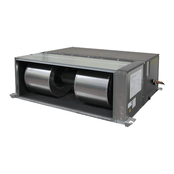
Mitsubishi Electric PEA-RP170 Installation Manual
Air-conditioners indoor unit
Hide thumbs
Also See for PEA-RP170:
- Operation manual (12 pages) ,
- Operation manual (8 pages) ,
- Operation manual (8 pages)
Table of Contents
Advertisement
Quick Links
- 1 Indoor Unit Accessories
- 2 Combining Indoor Units with Outdoor Units
- 3 Refrigerant Piping Work
- 4 Electrical Wiring
- 5 Power Supply Wiring
- 6 Connecting Remote Controller, Indoor and Outdoor Transmission Cables
- 7 Function Settings (Function Selection Via the Remote Controller)
- Download this manual
See also:
Operating Manual
Advertisement
Table of Contents

Summary of Contents for Mitsubishi Electric PEA-RP170
-
Page 1: Installation Manual
Air-Conditioners INDOOR UNIT PEA-RP170,200 WHA INSTALLATION MANUAL For safe and correct use, please read this installation manual thoroughly before installing the air-conditioner unit. - Page 2 [Fig. 3.2.1] 1100 1350 Keep the service space for the maintenance from the bottom when the heat exchanger is cleaned. 1100 1250 1324 more than 100 A Access door B Electrical parts box C Air inlet D Air outlet E Ceiling surface [Fig.
- Page 3 [Fig. 7.1.1] [Fig. 7.1.2] A Cool by a wet cloth A Cut here B Remove brazed cap [Fig. 7.1.3] A Thermal insulation tubing (small) B Caution: Pull out the thermal insulation on the refrigerant piping at the site, braze the piping, and replace the insulation in its original position.
- Page 4 [Fig. 8.0.1] A Air inlet B Air filter (supplied at site) C Duct D Canvas duct E Access door F Ceiling G Ensure sufficient length to prevent short cycling H Air outlet I Keep duct-work length 850 mm or more [Fig.
- Page 5 [Fig. 9.3.3] E Use PG bushing to keep the weight of the cable and external force from being I Power source terminal bed applied to the power supply terminal connector. Use a cable tie to secure the J Terminal bed for indoor transmission cable.
-
Page 6: Table Of Contents
• Always use an air cleaner, humidifier, electric heater, and other accesso- deteriorate. ries specified by Mitsubishi Electric. - Ask an authorized technician to install the accessories. Improper installation • Use refrigerant piping made of C1220 (Cu-DHP) phosphorus deoxidized copper as specified in the JIS H3300 “Copper and copper alloy seamless... -
Page 7: Before Getting Installed
• Use ester oil, ether oil or alkylbenzene (small amount) as the refrigerator • Install the power cable so that tension is not applied to the cable. oil to coat flares and flange connections. - Tension may cause the cable to break and generate heat and cause a fire. - The refrigerator oil will degrade if it is mixed with a large amount of mineral oil. -
Page 8: Install The Indoor Unit On A Ceiling Strong Enough To Sustain Its Weight
• At a distance 1 m or more away from your TV and radio (to prevent picture from 3.2. Securing installation and service space being distorted or noise from being generated). • Select the optimum direction of supply airflow according to the configuration of •... -
Page 9: Refrigerant Pipe And Drain Pipe Specifications
6.1. Refrigerant pipe and drain pipe specifications Model 170·200 Item Refrigerant pipe Liquid pipe ø 9.52 (Brazing connection) Gas pipe ø 25.4 Drain pipe O.D. ø 32 6.2. Refrigerant pipe, drain pipe [Fig. 6.2.1] (P.2) A Air inlet B Refrigerant piping (liquid) C Refrigerant piping (gas) D Control box E Drain pipe... -
Page 10: Duct Work
8. Duct work • When connecting ducts, insert a canvas duct between the main body and the [Fig. 8.0.1] (P.4) duct. A Air inlet B Air filter (supplied at site) C Duct D Canvas duct • Use non-combustible duct components. E Access door F Ceiling •... -
Page 11: Connecting Electrical Connections
Caution: 9.4. Function settings (Function selection Install wiring so that it is not tight and under tension. Wiring under tension via the remote controller) may break, or overheat and burn. 9.3. Connecting electrical connections 9.4.1 Function setting on the unit (Selecting the unit Please identify the model name of the operation manual attached on the terminal functions) bed box cover with that shown on the rating name plate. -
Page 12: Before Test Run
9.5. Before test run 9.6. Test run s s s s s After completing installation and the wiring and piping of the indoor and 9.6.1. Using wired remote controller outdoor units, check for refrigerant leakage, looseness in the power sup- 1 Turn on the power at least 12 hours before the test run. - Page 16 Please be sure to put the contact address/telephone number on this manual before handing it to the customer. HEAD OFFICE: TOKYO BLDG., 2-7-3, MARUNOUCHI, CHIYODA-KU, TOKYO 100-8310, JAPAN Authorized representative in EU: MITSUBISHI ELECTRIC EUROPE B.V. HARMAN HOUSE, 1 GEORGE STREET, UXBRIDGE, MIDDLESEX UB8 1QQ, U.K. WT05749X01...


Need help?
Do you have a question about the PEA-RP170 and is the answer not in the manual?
Questions and answers