
Subscribe to Our Youtube Channel
Related Manuals for Lectrosonics UCR511


Summary of Contents for Lectrosonics UCR511
-
Page 1: Operating Instructions
UCR511 UHF RECEIVER (Includes IFB Compatibility Mode) ™ Featuring Digital Hybrid Wireless Technology (US Patent Pending) OPERATING INSTRUCTIONS 0560 Rio Rancho, NM, USA www.lectrosonics.com... - Page 2 UCR511...
-
Page 3: Table Of Contents
ANTENNA USE AND PLACEMENT ......................14 INSTALLATION AND OPERATING INSTRUCTIONS ................15 FINDING CLEAR FREQUENCIES ..........................15 LOCKING AND UNLOCKING THE UCR511 FRONT PANEL CONTROLS ..............16 TO REPLACE THE BATTERIES ......................... 17 Frequency Coordination ..........................18 Compatible Frequency Chart ............................18 Rule No. - Page 4 Rule No. 2 ................................18 Rule No. 3 ................................20 Using the Scan Function .............................. 20 Call Lectrosonics ................................20 UCR511 REPLACEMENT PARTS AND ACCESSORIES ................. 21 TROUBLESHOOTING ..........................22 INITIAL POWER ON ..............................22 PILOT TONE SQUELCH .............................. 22 ANTENNAS AND RF SIGNAL STRENGTH ........................
-
Page 5: General Technical Description
However, due to the UCR511 receiver. It monitors user command inputs from flexibility of digital signal processing, the UCR511 is also the front panel control buttons and numerous other able to operate with Lectrosonics 300 Series, Lectroson-... -
Page 6: Digital Pulse Counting Detector
UCR511 is equipped (squelch). Brief delays (preset into the UCR511 cir- with a Smart Noise Reduction algorithm, which removes cuitry) eliminate thumps, pops or other transients that hiss without sacrificing high frequency response. -
Page 7: Rf-Controlled Digital Noise Filter
R.R/A.A (R.R is the RF board firmware To assist in matching the audio levels of equipment version, A.A is the audio board firmware connected to the UCR511, a 1 kHz audio test tone, version) adjustable from -50 to +5 dBu in 1 dB increments, is 3) COMPAT mode (mode is one of the following: available at the XLR connector. -
Page 8: Front Panel Controls And Functions
The LCD is used to provide feedback to the user on MENU menu selections and system operating conditions. The MENU pushbutton is used to rotate through the various set up menus of the UCR511.(See also Menu Selections From Main Window.) REAR PANEL FEATURES Audio Output XLR Jack... -
Page 9: Main Window (Lcd)
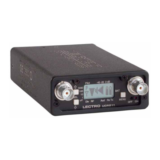
UHF Wireless Digital Hybrid Receiver MAIN WINDOW (LCD) Audio Levels - reference levels for audio signal modulation from transmitter Pilot -40 -20 0 dB 1000 Div RF Aud Rx Tx MENU LECTRO UCR 5 1 1 RF levels - reference for RF level screen icon portal to menu selections for setting up the receiver and The Main Window displays information concerning the... -
Page 10: Frequency Window
UCR511 MENU SELECTIONS FROM MAIN WINDOW Main Window Frequency Press All Buttons Scan Mode Pilot Off/On Hold MENU & press UP SELECT Press & Hold MENU Lock/Unlock Setup Window Press UP SETUP TV41 AE EXIT 631.800 Level Frequency Press SETUP... -
Page 11: Level
Four different types of batteries are commonly used ency is superior to the Lectrosonics SmtNR in Lectrosonics transmitters: 9 Volt alkaline, 9 Volt lithium, noise reduction system used for AA alkaline, and AA lithium. Correctly set, this will many years in the 300 series sys- ensure that adequate warning will be provided in ad- tems. -
Page 12: User Programmable Frequency Group Behavior
This mode offers the best audio quality. entry will only display that one frequency regardless of 100 - Lectrosonics 110 Series compatibility mode. how many times the SEL Up or Down buttons are pressed (providing the MENU button is not pressed at 300 - Lectrosonics 300 Series compatibility mode. -
Page 13: Frequency Scan Mode
In the FINE VIEW window, each vertical band represents will be displayed. Set your transmitter switches to the one frequency the UCR511 is capable of tuning. The same settings as shown on the display and your system upper right corner shows the transmitter switch settings will be ready for operation. -
Page 14: Antenna Use And Placement
Be careful about the length of cabling from antenna to receiver. alleviate the dropout problem at that location. If dropouts Long cable runs can have serious signal loss. Lectrosonics has in- are still a problem, try moving the unit to an entirely line RF amplifiers suitable for compensating for long cable runs. -
Page 15: Installation And Operating Instructions
UHF Wireless Digital Hybrid Receiver INSTALLATION AND OPERATING INSTRUCTIONS 1. Install a fresh battery or connect an external power source to the UCR511 and attaach the Output Level Adjust Squelch antennas. Non-Polar Caps 2 (HI) AUDIO 2. Unless frequency settings have been... -
Page 16: Locking And Unlocking The Ucr511 Front Panel Controls
RF activity. Scanning will and handling. repeat and continue until a button is pressed. To LOCK the UCR511 - Press and hold the MENU button until a bar tracks horizontally across the LCD screen and the word “LOCKED” appears. If the MENU button is released before the word “LOCKED”... -
Page 17: To Replace The Batteries
UHF Wireless Digital Hybrid Receiver TO REPLACE THE BATTERIES Lift and open the bottom battery door cover with your thumb, rotate the door until it is perpendicular with the case and allow the batteries to fall out of the compart- ment into your hand. -
Page 18: Frequency Coordination
UCR511 Frequency Coordination Intermodulation interference is a problem constantly labeled A and B and C and D, and correspond to the lurking in the background, especially when working in factory set frequency groups (Groups A, B, C and D) environments were multiple productions are taking place described in the Tuning Setup Screen. - Page 19 UHF Wireless Digital Hybrid Receiver Incompatible Compatible The following frequency The following frequency combinations have combinations have no intermodulation prob- intermodulation prob- lems and should not be lems. used. BLOCK 21 BLOCK 22 BLOCK 21 BLOCK 22 FREQ SW SET US TV CH FREQ SW SET...
-
Page 20: Rule No. 3
This service is ment in use nearby. The RF spectrum analyzer built into offered to authorized Lectrosonics dealers and other the UCR511 scans the frequency block to identify ™ ® customers who are using LECTRO or Lectrosonics wireless microphone and wireless IFB systems. -
Page 21: Ucr511 Replacement Parts And Accessories
(500 to 800 MHz). ARG15-ARG100 Coaxial cables for remote antennas are available from Lectrosonics in a variety of lengths - from 2 to 100 ft. Cables include Velcro tie wraps. Rio Rancho, NM – USA... -
Page 22: Troubleshooting
UCR511 TROUBLESHOOTING Symptom Possible Causes INITIAL POWER ON LCD display not active or lit. External power supply disconnected or inadequate. Main power supply fuse tripped. Turn the receiver off, remove the cause of the overload and turn the receiver back on. -
Page 23: Audio Signal Quality
If noise is still present when the transmitter is turned off, try lowering the audio output level on the UCR511 and see if the noise lowers correspondingly. If the noise remains, the problem is not in the receiver. -
Page 24: Specifications And Features
UCR511 SPECIFICATIONS AND FEATURES Operating Frequencies (MHz): Scanning mode: Coarse and fine modes for RF spectrum site Block 525: 525.000 - 550.500 scanning Block 21: 537.600 - 563.100 Audio test tone: 1 kHz, -50 dBu to +5 dBu output, less than Block 22: 563.200 - 588.700... -
Page 25: Service And Repair
UHF Wireless Digital Hybrid Receiver SERVICE AND REPAIR If your system malfunctions, you should attempt to correct or isolate the trouble before concluding that the equipment needs repair. Make sure you have followed the setup procedure and operating instructions. Check out the intercon- necting cords and then go through the TROUBLESHOOTING section in the manual We strongly recommend that you do not try to repair the equipment yourself and do not have the local repair shop attempt anything other than the simplest repair. - Page 26 I ETS 300 422; August 2002 and ENG 0950-1; 2001. A copy of the Declaration of Conformity may be requested from your dealer or by contacting the factory directly: Lectrosonics, Inc. Marketing Department 581 Laser Rd. NE, Rio Rancho, NM 87124 USA tel: 505-892-4501 fax: 505-892-6243 e-mail: marketing@lectrosonics.com...
- Page 27 UHF Wireless Digital Hybrid Receiver Rio Rancho, NM – USA...
-
Page 28: Limited One Year Warranty
This warranty does not apply to used or demonstrator equipment. Should any defect develop, Lectrosonics, Inc. will, at our option, repair or replace any defective parts without charge for either parts or labor. If Lectrosonics, Inc. cannot correct the defect in your equipment, it will be replaced at no charge with a similar new item.
Need help?
Do you have a question about the UCR511 and is the answer not in the manual?
Questions and answers